manuals.online logo
Brands
  1. Home
  2. •
  3. Brands
  4. •
  5. Siemens
  6. •
  7. Controllers
  8. •
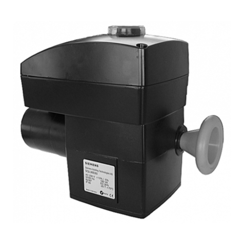
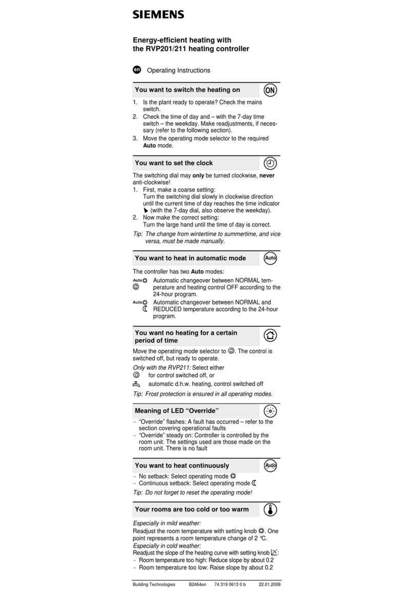
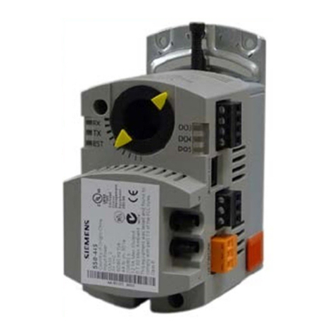
  9. Siemens OpenAir G B181.1E/KN Series User manual

Siemens OpenAir G B181.1E/KN Series User manual

This manual suits for next models

4

Other Siemens Controllers manuals

Siemens GEB-1E Series User manual

Siemens

Siemens GEB-1E Series User manual

Siemens SIMATIC S7-1200 User manual

Siemens

Siemens SIMATIC S7-1200 User manual

Siemens POLYCOOL RWR470.10 Operator's manual

Siemens

Siemens POLYCOOL RWR470.10 Operator's manual

Siemens GEB 4 Series User manual

Siemens

Siemens GEB 4 Series User manual

Siemens GNA 1E Series User manual

Siemens

Siemens GNA 1E Series User manual

Siemens M50 User manual

Siemens

Siemens M50 User manual

Siemens SAS61.03U User manual

Siemens

Siemens SAS61.03U User manual

Siemens Acvatix SAS31.03 User manual

Siemens

Siemens Acvatix SAS31.03 User manual

Siemens RVP201.0 User manual

Siemens

Siemens RVP201.0 User manual

Siemens SSA31.04 User manual

Siemens

Siemens SSA31.04 User manual

Siemens REV200 Series User manual

Siemens

Siemens REV200 Series User manual

Siemens SIPART DR21 User manual

Siemens

Siemens SIPART DR21 User manual

Siemens Powermite 599 Series Owner's manual

Siemens

Siemens Powermite 599 Series Owner's manual

Siemens SIMATIC S7-400H User manual

Siemens

Siemens SIMATIC S7-400H User manual

Siemens Sinamics S120M User manual

Siemens

Siemens Sinamics S120M User manual

Siemens S7-1200 TELECONTROL User manual

Siemens

Siemens S7-1200 TELECONTROL User manual

Siemens RVP200 User manual

Siemens

Siemens RVP200 User manual

Siemens SEO520 User manual

Siemens

Siemens SEO520 User manual

Siemens RVL479 User manual

Siemens

Siemens RVL479 User manual

Siemens N 512/21 User manual

Siemens

Siemens N 512/21 User manual

Siemens SQM40 Series Owner's manual

Siemens

Siemens SQM40 Series Owner's manual

Siemens instabus JB520C23 User manual

Siemens

Siemens instabus JB520C23 User manual

Siemens SIMATIC S5-95F User manual

Siemens

Siemens SIMATIC S5-95F User manual

Siemens 81000 series User manual

Siemens

Siemens 81000 series User manual

Popular Controllers manuals by other brands

Sunricher SR-ZV9003T3-RGBW-US Installation

Sunricher

Sunricher SR-ZV9003T3-RGBW-US Installation

Ksenia intro Installation and configuration manual

Ksenia

Ksenia intro Installation and configuration manual

Inovance CAN200 Series manual

Inovance

Inovance CAN200 Series manual

Gauzy LC6 FLEX Controller Installation and operation guide

Gauzy

Gauzy LC6 FLEX Controller Installation and operation guide

Viking SLP-1 Technical practice

Viking

Viking SLP-1 Technical practice

CKD KBX-30E-U Series instruction manual

CKD

CKD KBX-30E-U Series instruction manual

Sharp Energy Sun Flux User manual & installation guide

Sharp Energy

Sharp Energy Sun Flux User manual & installation guide

Yamaha RCX40 user manual

Yamaha

Yamaha RCX40 user manual

AB Quality PowerFlex 400 Frames D-H Service bulletin

AB Quality

AB Quality PowerFlex 400 Frames D-H Service bulletin

Yamaha MJC8 owner's manual

Yamaha

Yamaha MJC8 owner's manual

AL-KO ATC operating instructions

AL-KO

AL-KO ATC operating instructions

Savant SmartControl 2 Deployment guide

Savant

Savant SmartControl 2 Deployment guide

GameSir T3S user manual

GameSir

GameSir T3S user manual

Kostal inveor operating manual

Kostal

Kostal inveor operating manual

Emerson Yarway 20-55 Operating and safety instructions

Emerson

Emerson Yarway 20-55 Operating and safety instructions

CoCo ACM-LV24 Quick installation guide

CoCo

CoCo ACM-LV24 Quick installation guide

Brooks SLA5810/20 Installation and operation manual

Brooks

Brooks SLA5810/20 Installation and operation manual

SIGMA TEK SR 011 Technical manual

SIGMA TEK

SIGMA TEK SR 011 Technical manual

manuals.online logo
manuals.online logoBrands
  • About & Mission
  • Contact us
  • Privacy Policy
  • Terms and Conditions

Copyright 2025 Manuals.Online. All Rights Reserved.

CE1N3547en_c Siemens
2018-10-10 Building Technologies
OpenAir™
VAV Compact Controller KNX / PL-Link
G..B181.1E/KN
VAV Compact Controller 5 / 10 Nm with KNX communication
●GDB181.1E/KN with 5 Nm nominal torque
●GLB181.1E/KN with 10 Nm nominal torque
●Operating voltage AC 24 V
●Supports KNX S-Mode, LTE-Mode, and PL-Link
●For plants with variable or constant air-volume flow
●Actual values for volume flow, damper position and differential pressure
●Operating modes for volume flow control or position control
s
2 / 12
Siemens CE1N3547en_c
Building Technologies 2018-10-10
Type summary
Product no. Stock no. Operating
voltage Positioning
signal Power
consumption Positioning
time Manual
adjuster Position
feedback
GDB181.1E/KN S55499-D134
AC 24 V KNX-TP 1 VA / 0,5 W
3 VA / 2,5 W 1) 150 s Yes Yes
GLB181.1E/KN S55499-D135
Please refer to data sheet N4698 for information on accessories and spare parts.
1) Actuator rotates
Ordering (Example)
Product no. Stock no. Description Amount
GDB181.1E/KN S55499-D134 VAV Compact Controller KNX 1
Equipment combinations
Product no. Stock no. Description Doc. number / reference
AST20 S55499-D165 Handheld tool for commissioning and service A6V10631836
AST22 S55499-D373 USB/PPS2 Interface Converter A6V11236956
ACS931 Software PC Software for OEMs N5853
ACS941 Software PC Software for Service N5852
ETS Software KNX Engineering Tool www.knx.org
ACS790 Software Synco Engineering Tool CE1N5649
ABT Site Software Desigo Engineering/Commissioning Tool A6V11159913
Software versions
VAV Compact Controllers series G are designed for using ETS device profile v2.x, however
ETS device profile v1.x is supported for backward compatibility reasons.
Firmware / software version Series E Series F Series G
Production period 10/2011 – 03/2014 03/2014 – 01/2017 01/2017
Bus module FW version 4.16 4.18 4.24
ETS device profile v1.x supported supported supported
ETS device profile v2.x not supported not supported supported
Product documentation
Title Topic Document ID
VAV Compact Controllers KNX /
PL-Link – Technical Basics
Detailed information about the VAV compact
controllers with KNX / PL-Link communication
P3547
Mounting Instruction VAV Compact
Controllers KNX / PL-Link
Mounting / installation instruction for VAV compact
controllers KNX / PL-Link 5 / 10 Nm
M3547
How to obtain documentation and product-related software
Related documents such as environmental declarations, CE declarations, etc., can be down-
loaded at the following Internet address:
http://siemens.com/bt/download
The ETS device profile can be downloaded at the following Internet address:
http://siemens.com/hvac-td
3 / 12
CE1N3547en_c Siemens
2018-10-10 Building Technologies
Notes
Limitations
VAV compact controllers are not suitable for environments where the air is saturated with
sticky or fatty particles or contain aggressive substances.
Safety
Caution
National safety regulations
Failure to comply with national safety regulations may result in personal injury and
property damage.
●Observe national provisions and comply with the appropriate safety regulations.
Mounting
●Do not open the damper actuators.
●Do not use the accessory mounting holes for fixation of the damper actuators.
Mounting positions
IP54 protection in following mounting positions Accessory mounting holes 2)
Cf. mounting instr. M3547
2) Not to be used for fixation of the actuator, use anti-rotation-bracket instead.
Maintenance
The damper actuators are maintenance-free.
Disconnect the electrical connections from the terminals if you want to work at the device.
Disposal
The device is considered electrical and electronic equipment for disposal in
terms of the applicable European Directive and may not be disposed of as do-
mestic garbage.
∂Dispose of the device through channels provided for this purpose.
∂Comply with all local and currently applicable laws and regulations.
4 / 12
Siemens CE1N3547en_c
Building Technologies 2018-10-10
HMI (Human-Machine Interface)
Push-button operation
Activity Push-button operation Confirmation
Enter / leave addressing mode Press button < 1s LED turns red or turns off
Reset to factory settings Press button > 20s LED flashes orange until device restarts
PL-Link connection test 3) Press key >2s and < 20s LED flashes 1x orange
LED colors and patterns
Color Pattern Description
Off --- Fault free operation or device not powered
Green steady Connection test successful 3)
Orange flashing a) Factory reset in progress
b) When a connection test was triggered: wait 3)
Red steady c) Device is in programming/addressing mode
d) When a connection test was triggered: Connection test failed 3)
3) Function or part of the function available in PL-Link operation only
Addressing and bus test with push button
The VAV compact controllers can be set into addressing/programming mode by push-button:
ƒPress push button (>0.1s and <1s)
ƒKNX bus wiring OK ⇓LED turns red until addressing/programming is finished
ƒKNX bus wiring not OK ⇓LED stays dark
Reset with push button
The VAV compact controllers can be reset reset to the OEM default values by push-button:
ƒPress push button > 20s ⇓LED flashes orange ⇓Device restarts
PPS2 programming interface (with AST20 or AST22)
For OEM factory programming or commissioning / maintenance tasks directly at the VAV
compact controller, a suitable tool (cf. equipment combinations) can be connected to the
PPS2 interface.
Connection to the PPS2 interface
1 AST20 (or PC with ACS931 / ACS941 over AST22)
2 G..B181.1E/.. , or ASV181.1E/3
3 Strain release strip
4 Connection cable (7-pin)
12
3
4
5 / 12
CE1N3547en_c Siemens
2018-10-10 Building Technologies
Operating modes
Volume flow control (VAV or CAV)
Variable air volume (VAV) control: the operating point is determined by the setpoint value
and the Vmin / Vmax settings (cf. diagram below). Constant air volume (CAV) control is
achieved by sending a constant setpoint or by setting Vmin = Vmax.
1 Setpoint range
2 Actual value range
3 Controlled area
Position control
The VAV compact controllers can be operated as damper actuators, i.e. using the 0..100%
setpoint as position damper setpoint, by setting the operating mode parameter to “POS”.
Commissioning and parameterization
Parameterization of the VAV application
VAV application parameters are set by the OEM over the PPS2 interface (using ACS931 or
AST20). Some of them can be adjusted during commissioning, operation, or maintenance
and are accessible over a bus connection alternatively.
Parameter Range Description Factory settings
Operating mode VAV / POS VAV: setpoint = volume flow 0…100%
POS: setpoint = damper position 0...100%
VAV
Opening direction CW (R) / CCW (L) Opening direction of air damper CW (R)
Adaptive positioning Off / On Adaption of actual (if mech. limited) opening range
to position feedback 0...100%
Off = No adaption / On = Pos. adaption
Off
Vmin -20…100% Minimum air volume flow, rel. to Vnom 0 %
Vmax 20…120% Maximum air volume flow, rel. to Vnom 100 %
Vnom 0…60‘000 m3/h Nominal air volume flow 100 m3/h
Box coefficient (Vn) 1…3.16 VAV box characteristic value, defined by the OEM 1.00
Altitude /
Elevation asl.
0…5000m
in 500m steps
Correction factor for diff. pressure sensor (select
n*500m value closest to local altitude)
500 m
Vmax [%]Vmin [%]
3
6 / 12
Siemens CE1N3547en_c
Building Technologies 2018-10-10
Parameterization of the KNX integration
KNX integration parameters are checked or set during engineering and commissioning in the
ETS engineering tool.
Parameter Range Description Factory settings
Tab card “standard”
Operating mode VAV / POS VAV: setpoint = volume flow 0…100%
POS: setpoint = damper position 0…100%
VAV
Adaptive positioning On / Off Adaption of actual (if mech. limited) opening range
to position feedback 0...100%
Off = No adaption / On = Pos. adaption
Off
Altitude /
Elevation asl.
0…5000m
in 500m steps
Correction factor for diff. pressure sensor (select
n*500m value closest to local altitude)
500 m
Backup timeout 0..60 min
0 min = disabled
Time interval to detect communication
interruption. If disabled, the actuator drives to the
last received setpoint until a new setpoint is
received.
30 min.
Backup mode Backup position
Keep last position
Actuator behavior when the communication
timeout has been exceeded (no setpoint received
within the defined time interval).
ƒBackup position: Actuator drives to defined
position
ƒKeep last position: Actuator keeps position
without flow control
Backup position
Backup position 0…100% Position the damper drives to in case of
communication interruption
50%
Tab card “advanced”
Hysteresis (COV)4)
volume flow
1...20% Threshold for the relative volume flow.
COV below this value are not sent over the bus.
1%
Min. repetition time
volume flow
10...900 s Minimum waiting time until a COV above the
hysteresis threshold is sent over the bus
10 s
Hysteresis (COV)
damper position
1...20% Threshold for the damper position. COV below
this value are not sent over the bus
1%
Min. repetition time
damper position
10...900 s Minimum waiting time until a COV above the
hysteresis threshold is sent over the bus
10 s
Override position 1 0...100% Damper position which can be triggered by the
corresponding group object
0%
Override position 2 0…100% Damper position which can be triggered by the
corresponding group object
100%
Write Vnom On / Off If checked, the group object for Vnom is writable
(OEM parameter protection applies), otherwise it
is read-only.
Off
Write Opening
Direction
On / Off If checked, the group object for the opening
direction is writable (OEM parameter protection
applies), otherwise it is read-only.
Off
4) Change-of-value
7 / 12
CE1N3547en_c Siemens
2018-10-10 Building Technologies
KNX Group Objects
Group Objects Table
Nr. Name in ETS Object
function Flags Data point type KNX Range
C R W T U ID DPT_Name Format Unit
1Fault information Transmit 1 1 0 1 0 219.001 _AlarmInfo 6 Byte --- cf. Group Objects Descr.
2Fault state Transmit 1 1 0 1 0 1.005 _Alarm 1 bit --- 0 = No alarm / 1 = Alarm
3Fault transmission Receive 1 0 1 0 1 1.003 _Enable 1 bit --- 0 = Disable / 1 = Enable
4Setpoint Receive 1 1 1 0 1 5.001 _Scaling 1 Byte % 0…100%
5Damper position Transmit 1 1 0 1 0 5.001 _ Scaling 1 Byte % 0...100%
6Volume flow
relative 5) Transmit 1 1 0 1 0 5.001 _ Scaling 1 Byte % 0...100%
Transmit 1 1 0 1 0 8.010 _Percent_V16 2Bytes % -327.68...327.67%
Transmit 1 1 0 1 0 5.004 _ Percent_U8 1 Byte % 0...255%
7Volume flow
absolute 5) Transmit 1 1 0 1 0 9.009 _Value_Airflow 2Bytes m
3
/h -670 760...670 760 m3/h
Transmit 1 1 0 1 0 14.077 _ Volume_Flux 4Bytes m
3
/s 0…(2
32
-1)
8Fault Transmit 1 1 0 1 0 1.005 _Alarm 1 bit --- 0 = No alarm / 1 = Alarm
9Overridden Transmit 1 1 0 1 0 1.002 _Bool 1 bit --- 0 = False / 1 = True
10 Override position 1 Receive 1 1 1 0 1 1.003 _Enable 1 bit --- 0 = Disable / 1 = Enable
11 Override position 2 Receive 1 1 1 0 1 1.003 _Enable 1 bit --- 0 = Disable / 1 = Enable
12 Balancing mode Receive 1 1 1 0 0 1.003 _Enable 1 bit --- 0 = Disable / 1 = Enable
13 Vmin Receive 1 1 1 0 1 8.010 _Percent_V16 2Bytes % -327.68...327.67%
14 Vmax Receive 1 1 1 0 1 8.010 _Percent_V16 2Bytes % -327.68...327.67%
15 Vnom Read-only 1 1 0 0 0 9.009 _Value_Airflow 2 Bytes m3/h -670 760...670 760 m3/h
16 Opening direction Read-only 1 1 0 0 0 1.012 _Invert 1 bit --- 0 = Not Inverted / 1 = Inv.
17 Diff. pressure
5)
Read-only 1 1 0 0 0 9.006 _Value_Pres 2 Bytes Pa 0...670 760 Pa
Read-only 1 1 0 0 0 14.058 _Value_Pressure 4 Bytes Pa 0...(2
32
-1)
18 Coefficient Read-only 1 1 0 0 0 14.* 4-Byte Float 4 Bytes --- 0...3.16
19 OEM-Reset Receive 1 0 1 0 0 1.017 _Trigger 1 bit --- 0, 1 = Trigger
5) For some group objects, alternative data point types (DPT) can be selected in ETS. The first entry indicates the default setting.
8 / 12
Siemens CE1N3547en_c
Building Technologies 2018-10-10
Group Objects Description
1 Fault information If group object #3 ”fault transmission” is set to “on”, the following faults can be transmitted if they
occur. In that case, group object #2 value changes to “alarm”.
Error Group obj. #1 Description Resolution
Device jammed 03 00 0A 03 0C 05 Target position can’t be
reached due to blockage.
Remove blockage (visual
inspection required) or
invert Opening direction,
if it is set wrongly
Or switch on adaptive
positioning, if mechanical
limits are intended.
Backup mode
entered
00 01 01 02 0C 05 Actuator is in backup mode
(cf. respective parameter
setting)
Actuator leaves Backup
mode when receiving a
setpoint.
Pressure sensor
tubes inverted
00 01 0A 01 0C 05 Pressure sensor measures
the lower pressure on the
input marked with “+”.
Correct the tubes
connection
Pressure sensor
malfunction
00 01 0A 01 0C 05 Malfunction of internal
communication to dp sensor
(200 ms timeout)
1) Check tubes
connection, or
2) reboot device, or
3) replace device
Operating hours
notification
00 01 0A 04 0C 05 Appears after a cumulated
motor running time of 365
days
Check device status and
control loop sensitivity
2 Fault state Indicates whether the actuator is in fault state. If yes, read out group object #1.
3 Fault transmission Enabling/ disabling the fault transmission. Fault transmission is disabled by default; therefore no
faults are transmitted from the actuator over the KNX bus.
4 Setpoint Setpoint 0…100% for volume flow or position, depending on the operating mode.
5 Damper position Relative damper position 0…100%. An opening range less than 0…90° can be normalized to
0...100% if adaptive positioning is set to “on”.
6 Volume flow relative Volume flow relative to the settings of Vnom, Vmin, and Vmax.
7 Volume flow absolute Volume flow in m
3
/h or m
3
/s depending on the selected data type.
8 Fault Same function as group object #2 (available for compatibility reasons).
9 Overridden Indicates whether the VAV controller is in override control either by a programming tool connected to
the HMI or by objects #10 / #11.
10 Override position 1 When the object is triggered, the actuator drives to the override position 1 defined by the respective
ETS parameter.
11 Override position 2 When the object is triggered, the actuator drives to the override position 2 defined by the respective
ETS parameter.
12 Balancing mode When the object is triggered, the actuator drives to Vmax for air balancing purposes.
13 Vmin Minimum air volume flow relative to Vnom.
14 Vmax Maximum air volume flow relative to Vnom.
15 Vnom Nominal air volume flow (absolute).
16 Opening direction Opening direction of the air damper.
17 Diff. pressure Actual value of the differential pressure over the VAV box measuring cross.
18 Coefficient VAV box characteristic value to map a nominal differential pressure to the corresponding nominal
volume flow.
19 OEM-Reset Resets all parameters to the value specified by the OEM.
9 / 12
CE1N3547en_c Siemens
2018-10-10 Building Technologies
Technical data
Power supply
Operating voltage G..B181.1E/.. AC 24 V ± 20 % (SELV)
or
AC 24 V class 2 (US)
Frequency 50/60 Hz
Power consumption at 50 Hz
Actuator holds 1 VA / 0.5 W
Actuator rotates 3 VA / 2.5 W
Function data
Positioning time for
nominal rotation angle
G..B181.1E/.. 150 s (50 Hz)
125 s (60 Hz)
Nominal torque GDB.. 5 Nm
GLB.. 10 Nm
Maximum torque GDB.. < 7 Nm
GLB.. < 14 Nm
Nominal / maximum
rotation angle
90° / 95° ± 2°
Direction of rotation Adjustable by tool or over bus Clockwise (CW) /
Counter-clockwise (CCW)
Connection cables
Cable length 0.9 m
Power supply Number of cores and cross-sectional area 2 x 0.75 mm2
Communication Number of cores and cross-sectional area 2 x 0.75 mm2
Service interface Terminal strip 7-pin, grid 2.00 mm
Communication
Communication protocol Connection type KNX-TP (galvanically isolated)
Bus load 5 mA
Degree of protection
Degree of protection Degree of protection acc. to EN 60529
(see mounting instruction)
IP54
Saf ety class Safety class acc. to EN 60730 III
Environmental conditions
Applicable standard IEC 60721-3-x
Operation Climatic conditions Class 3K5
Mounting location Indoors
Temperature general 0…50 °C
Humidity (non condensing) 5…95 % r. F.
Transport Climatic conditions Class 2K3
Temperature -25…70 °C
Humidity 5...95 % r. h.
Storage Climatic conditions Class 1K3
Temperature -5…45 °C
Humidity 5...95 % r. h.
10 / 12
Siemens CE1N3547en_c
Building Technologies 2018-10-10
Directives and Standards
Product standard EN60730-x
Electromagnetic compatibility (Application) For residential, commercial and industrial
environments
GDB181.1E/KN GLB181.1E/KN
EU Conformity (CE) A5W00003842 1) A5W00000176 1)
RCM Conformity A5W00003843 1) A5W00000177 1)
UL, cUL AC 24 V UL 873 http://ul.com/database
Environmental compatibility
The product environmental declaration A6V10209938 1) contains data on
environmentally compatible product design and assessments (RoHS compliance,
materials composition, packaging, environmental benefit, disposal).
Dimensions / Weight
Weight Without packaging 0.6 kg
Dimensions 71 x 158 x 61 mm
Suitable drive shafts Round shaft (with centering element) 8...16 mm (8...10 mm)
Square shaft 6...12.8 mm
Min. drive shaft length 30 mm
Max. shaft hardness <300 HV
Air volume flow controller
Type 3-position controller with hysteresis
Vmax, adjustable resolution 1% / factory setting 100% 20%...120%
Vmin, adjustable resolution 1% / factory setting 0% -20%...100%
Vn = f(dpn), adjustable resolution 0.01 / factory setting 1.00 1.0…3.16
Differential pressure sensor
Connection tubes (Interior diameter) 3…8 mm
Measuring range 0…500 Pa
Operating range 0…300 Pa
Precision at 23 °C, 966
mbar and optional
mounting position
Zero point ± 0.2 Pa
Amplitude ± 4.5 % of the measured value
Drift ± 0.1 Pa / Year
Max. permissible operating pressure 3000 Pa
Max. permissible overload on one side 3000 Pa
1) The documents can be downloaded from http://siemens.com/bt/download