0611 RM500SLUser’sGuide Version 2.8Page 2
1AboutRM500SL.................................................................................................................6
1.1 Section overview......................................................................................................................6
1.2 Newinthissoftwarerelease.....................................................................................................7
1.3 Electronicuser’sguide.............................................................................................................7
1.4 Warranty,Trademarks,Acknowledgements..............................................................................8
1.5 Noticesforthe European Community.......................................................................................9
1.6 Declaration ofEMCcomplianceforthe European Community..................................................9
2Getting Started.................................................................................................................10
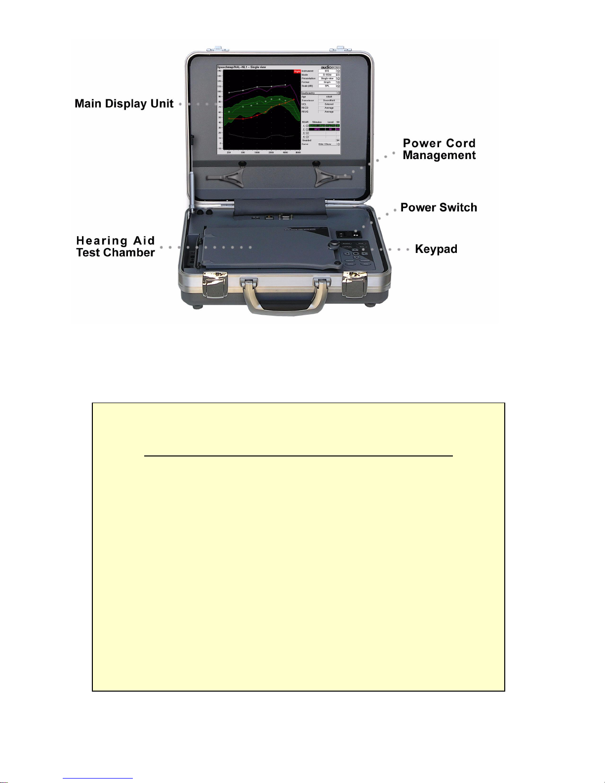
2.1 Section overview....................................................................................................................10
2.2 Unpacking and connecting.....................................................................................................10
2.3 Microphone connection..........................................................................................................11
2.4 Microphone care....................................................................................................................12
2.5 Battery pilluseand care.........................................................................................................12
2.6 Mouse, keyboard, barcode scanner........................................................................................13
2.7 External printer, auxiliaryaudiooutputs..................................................................................14
3GeneralOperation...........................................................................................................14
3.1 Section overview....................................................................................................................14
3.2 Input deviceoperation............................................................................................................15
3.3 Barcode datainput.................................................................................................................16
3.4 Keypad keys..........................................................................................................................17
3.5 Menus, listsand buttons.........................................................................................................18
3.6 Screen messages..................................................................................................................19
3.7 Programmemoryremoval and replacement...........................................................................19
3.8 Softwareupdating..................................................................................................................20
4GeneralSetup..................................................................................................................20
4.1 Section overview....................................................................................................................20
4.2 Dateand timesetup...............................................................................................................20
4.3 Displaysettings......................................................................................................................21
4.4 Saving test setup...................................................................................................................21
5Networking.......................................................................................................................22
5.1 Section overview....................................................................................................................22
5.2 Networking requirements........................................................................................................22
5.3 Networking setup...................................................................................................................23
5.4 Singlecomputerconnection...................................................................................................24
6Printing and Storing Results...........................................................................................25
6.1 Section overview....................................................................................................................25
6.2 Internalprinterpaperloading..................................................................................................26
6.3 Barcodes, headersand commentson printouts......................................................................27
6.4 Localprintersetup..................................................................................................................27
6.5 Printing toaUSBmemorystick..............................................................................................28
6.6 Network printersetup.............................................................................................................29