audioscan verifit User manual

Audioscan Verifit®
User's Guide 4.8
© November 2016

Table of Contents
1 About Verifit..........................................................................................................................................................................6
Product description...............................................................................................................................................................6
Accessories.........................................................................................................................................................................12
Associated items and supplies............................................................................................................................................12
SAFETY WAR I GS and OTICES..............................................................................................................................13
Environmental safety..........................................................................................................................................................14
Declaration of Electromagnetic Compatibility (EMC).....................................................................................................14
Warranty, Trademarks, Acknowledgments.......................................................................................................................15
EC Declaration of Conformity...........................................................................................................................................17
Electronic User’s Guide.....................................................................................................................................................18
How to Avoid Undesirable Side Effects............................................................................................................................18
2 Getting Started.....................................................................................................................................................................20
Office setups.......................................................................................................................................................................20
Unpacking and connecting.................................................................................................................................................20
Microphone connection......................................................................................................................................................22
General care instructions....................................................................................................................................................24
Microphone care.................................................................................................................................................................24
Mouse and keyboard...........................................................................................................................................................25
Monitor headphones...........................................................................................................................................................25
External peripherals............................................................................................................................................................27
3 General Operation................................................................................................................................................................28
Switching O /OFF.............................................................................................................................................................28
Input device operation........................................................................................................................................................28
etwork connection............................................................................................................................................................30
Printer connection...............................................................................................................................................................31
Menus, lists and buttons.....................................................................................................................................................32
Screen messages and Help.................................................................................................................................................32
Software updating...............................................................................................................................................................32
4 General Setup.......................................................................................................................................................................34
Date and time setup............................................................................................................................................................34
Display settings...................................................................................................................................................................34
Saving test setup.................................................................................................................................................................34
5 On-Ear Measures - Setup.....................................................................................................................................................36
External sound field speaker setup....................................................................................................................................36
On-ear calibration facts......................................................................................................................................................37
Calibration of on-ear probe microphone............................................................................................................................37
Calibration check for probe module..................................................................................................................................39
Max TM SPL setup............................................................................................................................................................40
ABR nHL to eHL setup......................................................................................................................................................40
Positioning the client..........................................................................................................................................................40
Positioning the probe tube..................................................................................................................................................41
6 On-Ear Measures Screen Setup...........................................................................................................................................43
On-ear single or dual view.................................................................................................................................................43
Graph, table or 2cc target format.......................................................................................................................................43
SPL or HL scale..................................................................................................................................................................43
Hide or show on-ear curves................................................................................................................................................43
7 Speechmap...........................................................................................................................................................................45
Speechmap facts.................................................................................................................................................................45
DSL 5 in Speechmap..........................................................................................................................................................45
AL- L1 in Speechmap....................................................................................................................................................46
AL- L2 in Speechmap....................................................................................................................................................46
Camfit in Speechmap.........................................................................................................................................................46
Using Speechmap...............................................................................................................................................................47
Speechmap Setup................................................................................................................................................................47
Screen tour - unaided screen..............................................................................................................................................49
Screen tour - aided screen..................................................................................................................................................50

Verifit®User's Guide Version 4.8 © November 2016
On-ear or Test box mode....................................................................................................................................................50
SII calculation in Speechmap.............................................................................................................................................51
Using custom stimuli in Speechmap..................................................................................................................................51
Creating WAV files for Speechmap..................................................................................................................................53
8 Speechmap Fitting Procedures............................................................................................................................................55
Speechmap screen choices.................................................................................................................................................55
Data entry...........................................................................................................................................................................57
Fitting to targets for soft speech.........................................................................................................................................57
Fitting to targets for average speech .................................................................................................................................58
Adjusting the Maximum Output Level..............................................................................................................................59
Open fittings in Speechmap...............................................................................................................................................60
Verifying Frequency Compression/ Frequency-Lowering Hearing Instruments in Speechmap......................................61
Binaural fitting in Speechmap...........................................................................................................................................62
CROS fitting in Speechmap...............................................................................................................................................63
T-Loop fitting and verification in Speechmap..................................................................................................................64
Tele-test fitting and verification in Speechmap................................................................................................................65
FM fitting and verification.................................................................................................................................................67
How to Verify with Calibrated 'S' and 'SH' Stimuli..........................................................................................................67
9 Speechmap Technical Details..............................................................................................................................................69
Wideband measurements in Speechmap............................................................................................................................69
Speechmap stimuli.............................................................................................................................................................69
Stimulus spectra..................................................................................................................................................................70
Microphone location effects...............................................................................................................................................72
Deep insertion compensation.............................................................................................................................................72
Speech signal analysis........................................................................................................................................................73
10 On-Ear Instrument Measures.............................................................................................................................................74
On-ear directional test overview........................................................................................................................................74
On-ear directional testing...................................................................................................................................................74
On-ear feedback test...........................................................................................................................................................75
On-ear noise reduction test.................................................................................................................................................75
On-ear noise reduction stimuli...........................................................................................................................................76
On-ear manual control........................................................................................................................................................76
Sound level meter using on-ear microphones....................................................................................................................77
11 WRECD measurement.......................................................................................................................................................78
Calibration of WRECD Transducer...................................................................................................................................78
Measure WRECD ..............................................................................................................................................................79
WRECD results..................................................................................................................................................................80
WRECD protocols..............................................................................................................................................................81
WRECD facts.....................................................................................................................................................................82
12 Occlusion Effect Test.........................................................................................................................................................83
Occlusion effect measurement...........................................................................................................................................83
13 Sensory loss simulator.......................................................................................................................................................84
Sensory loss simulator description.....................................................................................................................................84
Sensory loss simulator operation.......................................................................................................................................84
14 Insertion Gain.....................................................................................................................................................................86
Insertion gain in SPL..........................................................................................................................................................86
Insertion gain in HL...........................................................................................................................................................87
Audiometric data entry.......................................................................................................................................................88
REUR measurement procedure..........................................................................................................................................89
REAR measurement procedure..........................................................................................................................................90
SII calculation in Insertion gain.........................................................................................................................................90
CROS fitting using Insertion gain......................................................................................................................................91
3

Verifit®User's Guide Version 4.8 © November 2016
15 Test Box Measures - Setup................................................................................................................................................93
Test box screen...................................................................................................................................................................93
Format.................................................................................................................................................................................95
Scale....................................................................................................................................................................................95
Hide or Show test box curves.............................................................................................................................................95
A SI test frequencies.........................................................................................................................................................96
Test box calibration facts...................................................................................................................................................97
Calibrating test box reference microphone........................................................................................................................97
Calibration check for coupler microphone........................................................................................................................98
Coupling for binaural/wideband tests................................................................................................................................99
Positioning HI for binaural/wideband tests........................................................................................................................99
Coupling for A SI/IEC tests...........................................................................................................................................100
Positioning HI for A SI/IEC tests...................................................................................................................................101
16 A SI/IEC Hearing Aid Tests..........................................................................................................................................103
A SI S3.22-2003 and A SI S3.22-2009 facts................................................................................................................103
A SI 2003 and 2009/IEC tests........................................................................................................................................103
A SI test results...............................................................................................................................................................104
A SI input-output curves................................................................................................................................................104
A SI telecoil terminology...............................................................................................................................................105
A SI telephone simulator (TMFS) test...........................................................................................................................105
A SI test loop test............................................................................................................................................................106
Telecoil test results...........................................................................................................................................................107
17 Other Test Box Measures................................................................................................................................................108
Harmonic distortion..........................................................................................................................................................108
oise reduction.................................................................................................................................................................108
oise reduction stimuli....................................................................................................................................................109
Directional function test...................................................................................................................................................109
Directional ITE positioning..............................................................................................................................................110
Directional BTE positioning............................................................................................................................................110
Test box directional procedure.........................................................................................................................................111
Multicurve procedure.......................................................................................................................................................112
Multicurve results.............................................................................................................................................................112
Spectral analysis in Multicurve........................................................................................................................................113
Battery drain test..............................................................................................................................................................113
Manual control procedure................................................................................................................................................114
Sound level meter using manual control.........................................................................................................................115
18 etworking.......................................................................................................................................................................117
etworking standards.......................................................................................................................................................117
etwork setup...................................................................................................................................................................117
Remote Operation.............................................................................................................................................................119
Changing the Remote Operation settings........................................................................................................................120
TeleAudiology..................................................................................................................................................................120
Changing the TeleAudiology settings..............................................................................................................................120
OAH Service Port..........................................................................................................................................................121
Changing the OAH service port....................................................................................................................................121
Testing the OAH service port........................................................................................................................................122
Web Service Port..............................................................................................................................................................122
19 Single Computer Connection...........................................................................................................................................124
Automatic connection (recommended)............................................................................................................................124
Static connection..............................................................................................................................................................124
20 Printing and Storing Results............................................................................................................................................126
Storing data in OAH......................................................................................................................................................126
4

Verifit®User's Guide Version 4.8 © November 2016
Printing results..................................................................................................................................................................126
Printing setup....................................................................................................................................................................126
Printer connection.............................................................................................................................................................127
Printer types......................................................................................................................................................................128
HP printer..........................................................................................................................................................................128
Custom printer..................................................................................................................................................................128
File output.........................................................................................................................................................................129
Page setup.........................................................................................................................................................................129
Windows-shared printers and folders...............................................................................................................................131
etwork printer.................................................................................................................................................................133
Web browser screen capture............................................................................................................................................133
Session setup.....................................................................................................................................................................134
Storing and restoring session files....................................................................................................................................135
21 Troubleshooting...............................................................................................................................................................137
Self test failures................................................................................................................................................................137
Initialize Function............................................................................................................................................................137
Inconsistent levels in speech stimulus.............................................................................................................................138
Test box high distortion or noise......................................................................................................................................138
Test box curves inconsistent............................................................................................................................................138
Test box curves differ from specifications......................................................................................................................138
Test box speaker overdriven............................................................................................................................................139
o test box reference mic. detected.................................................................................................................................139
Invalid test box calibration...............................................................................................................................................139
Unable to calibrate test box microphone.........................................................................................................................139
o on-ear ref. mic. detected.............................................................................................................................................140
Invalid on-ear calibration.................................................................................................................................................140
Unable to calibrate on-ear microphone............................................................................................................................140
Sound field speaker overdriven........................................................................................................................................140
Binaural tests run twice....................................................................................................................................................141
Invalid binaural equalization............................................................................................................................................141
Invalid WRECD transducer coupler calibration..............................................................................................................141
Invalid RECD real ear measurement...............................................................................................................................141
Headphone high distortion or noise.................................................................................................................................142
22 Technical Specifications..................................................................................................................................................143
23 Glossary............................................................................................................................................................................150
24 References........................................................................................................................................................................155
25 Appendix 1.......................................................................................................................................................................158
Manufacturer Disclosure Statement for Medical Device Security.................................................................................158
5

Verifit®User's Guide Version 4.8 © November 2016
1 About Verifit
This section provides a listing of features new in this software release, describes the Audioscan Verifit, provides
contact, warranty and trademark information, safety warnings and notices and instructions for accessing the
electronic User’s Guide.
ote that the User's Guide may be viewed on the Verifit at any time by pressing <Help>. (For long Help pages,
use the mouse to switch between the Help index and the Help page, and to scroll through the page).
Product description
The Verifit is a hearing instrument analyzer intended to be used by hearing care professionals such as
audiologists and hearing instrument specialists to verify the electro-acoustic performance of a hearing
instrument connected to a standard earphone coupler or while worn on the ear of the end user. The Verifit is a
Programmable Electrical Medical System (PEMS). The system consists of a real-ear measurement (REM)
display unit, a hearing instrument test (HIT) acoustically-treated binaural test box, and numerous attachable
components and accessories:
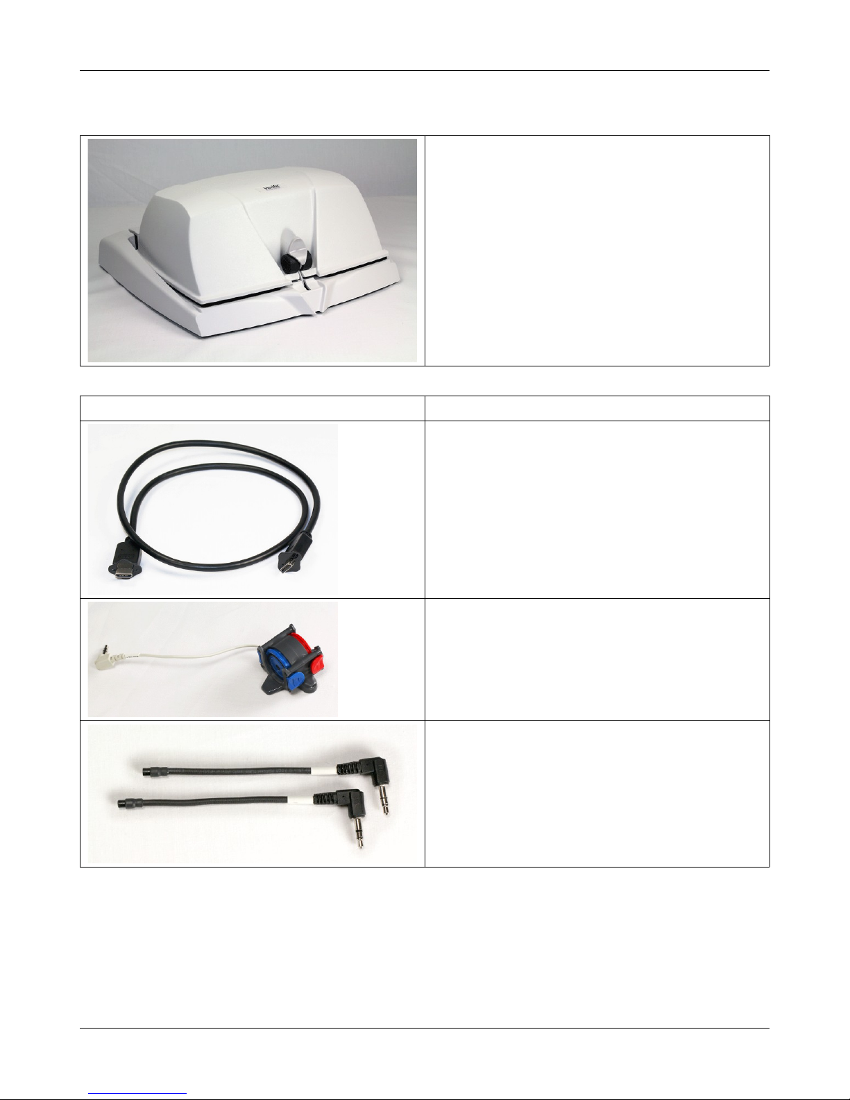
Display Unit
A real-ear measurement (REM) display unit housing a flat-
panel LCD high resolution display, signal generation,
measurement and control electronics, and two sound field
loudspeakers.
On the sides of the display unit, there are connections for:
1.monitor headphones on the lower right side
2.a USB jack on the lower left side (for the
Audioscan update stick, for example)
3.magnet mounts on both sides of the display unit,
approximately 8cm (3 in.) down from the top (this
is where you store the probe dock when not in use)
On the rear of the display unit, there are connections for:
1.an external monitor
2.a network connection
3.external loudspeakers
4.power supply
5.test box cable
6.probe dock cable
7.four USB jacks (for a keyboard, printer, and a
mouse) - the USB stick for the mouse is already
inserted into one of these USB jacks
The following components are shipped with the display unit
6

Verifit®User's Guide Version 4.8 © November 2016
Component Description
External power supply connected to a hospital grade power
cord (in orth America) or a country-specific power cord
(international markets) .
Electrical supply input requirement: 100 – 240 Vac
47 – 63 z 1.35 – 0.53 A
Probe dock, shown here with 2 probe microphones (which
nest into, and are connected to, the probe dock). This is the
configuration of these components when they are shipped to
you.
The probe dock has connections for the 2 probe microphones,
the WRECD transducer, and the tele-test handset. It is intended
that the probe dock clips near to or on the patient.
There is a probe cables adjust clip on the probe microphone
cables that allows you to adjust the probe microphones flat
against the client's cheek
Probe tubes, package of 36
7

Verifit®User's Guide Version 4.8 © November 2016
Component Description
WRECD transducer used to measure the wideband real-ear
to coupler difference (WRECD) useful in estimating the sound
level produced in an individual ear from measurements in a
coupler
Foam eartips for measuring WRECD. The package contains:
•Qty 5 ER3-14A adult foam eartips
•Qty 5 ER3-14B pediatric foam eartips
Wireless mouse
Monitor headphones provided with 2 detachable (detachable
from the headphone) cables, each having 3.5mm stereo plugs
on each end. The cables are 130cm (51 in.) and 365cm (12
feet) in length
a 3.5cm to 1/4-inch adapter plug is also provided (to connect to
the 1/4-inch headphone jack on the display unit)
8

Verifit®User's Guide Version 4.8 © November 2016
Component Description
ele-test handset used to provide an inductive stimulus for
simulating operation with a telephone in Speechmap and for
performing A SI TMFS test.
Audioscan update USB stick
Quickstart setup guide
9
Verifit®User's Guide Version 4.8 © November 2016
est Box
Hearing instrument test (HIT) acoustically-treated
binaural test box which houses a telecoil test loop,
3 loudspeakers and connections for:
•two reference microphones,
•binaural coupler microphone
•battery pill substitutes
The following components are shipped with the test box
Component Description
est box cable to connect the test box to the display unit
Binaural coupler microphone for the purpose of
measuring the sound level produced in the standard coupler
by a hearing instrument
estbox reference microphones for controlling the signal
from the loudspeakers (2)
10

Verifit®User's Guide Version 4.8 © November 2016
Component Description
0.4cc wideband couplers for Speechmap and all binaural/
wideband tests.
HA-1 (I E) 2cc coupler (1)
OTE: for A SI/IEC tests only. ot to be used for
Speechmap.
HA-2 (B E) 2cc coupler (1)
OTE: for A SI/IEC tests only. ot to be used for
Speechmap.
Hearing instrument stabilizers, attached to the 0.4cc
couplers to support BTE-style instruments
RIC adapters (Thin-tube, Receiver In Canal) designed
for use with 0.4cc and HA-1 (ITE) 2cc couplers
11

Verifit®User's Guide Version 4.8 © November 2016
Component Description
Earmold substitutes (HA-4 tubing) inserted in a second
set of TRIC adapters to allow BTE instruments to be
coupled to the 0.4cc coupler without earmold. Two
replacement tubes are also supplied. If this tubing cracks or
dries out replacements can be ordered from Audioscan
(part #3986, qty 6 per package)
Putty, to attach custom hearing instruments and earmolds
to the coupler 0.4cc and HA-1 (ITE) 2cc couplers
Battery pill substitutes, kit consisting of:
1 - E352 Battery Size #10A
1 - E353 Battery Size #13A
1 - E354 Battery Size #312
1 - E355 Battery Size #675
Accessories
RE367-36 probe tubes for single patient use (36 per bag)
ER3-14A and ER3-14B foam eartips (package containing 5 of each)
Associated items and supplies
VA-111 External speaker with folding stand
VA-131 Microphone extension cable (90cm / 36 in.) for use with binaural coupler microphone
VA-134 Probe dock extension cable (375cm / 12 ft.) for use with the probe dock
VA-201 OAH® module allows a networked PC running OAH to exchange data with Audioscan analyzers
RE-791 Binaural coupler microphone adapter for use with B&K 4231 or Quest QC10/20 calibrators (1 in.)
12

Verifit®User's Guide Version 4.8 © November 2016
SAFETY WARNIN S and NOTICES
For purposes of IEC 60601-1, this product is Class I with ype BF applied parts. he applied parts are:
1.Probe tube
2.Foam eartip
3.Probe microphone
his device complies with Part 15 of the FCC Rules. Operation is subject to the following two conditions:
(1) this device may not cause harmful interference, and (2) this device must accept any interference
received, including interference that may cause undesired operation
his Class A digital apparatus complies with Canadian ICES-003
This symbol on the product is a WAR I G describing a foreseen risk
WARNING: To avoid the risk of electrical shock, use only the power supply and power cord supplied with
the Verifit and connect it only to a grounded (protectively earthed) electrical outlet.
WARNING: To allow electrical power to be rapidly disconnected in the event of an emergency, position the
power supply in an accessible location so that the power cord may be quickly disconnected.
WARNING: To avoid the risk of electrical shock, any line-powered peripheral equipment connected to this
product must comply with UL/IEC 60601-1 OR comply with UL or IEC and ISO safety standards for such
equipment A D a) be operated from an isolating transformer complying with UL/IEC 60601-1 OR b) be kept
at least 1.8m (6 ft.) from the patient.
WARNING: This equipment is not suitable for use in an oxygen-rich environment or in the presence of
flammable anesthetic mixtures with air or with oxygen or nitrous oxide.
WARNING: To ensure proper operation of this product, no modification of this equipment is permitted
WARNING: Probe tubes are for single-patient use only. Care is required when sliding the probe tube into the
ear canal. Be careful not to advance the probe tube further into the ear canal when inserting an earmold or
custom hearing instrument into the ear or when inserting the foam tip into the ear
WARNING: Foam eartips are for single-patient use only
WARNING: To ensure that the operation of this product is not affected by EMC emissions from other
products, this product should not be used adjacent to or stacked on other equipment. If this is necessary, its
operation should be verified as normal in this configuration. Portable and mobile RF communications
equipment can affect the performance of this product
WARNING: To reduce the risk of contamination, hearing instruments should be clean before putty is applied
and putty should be replaced frequently
WARNING: The included magnet may effect some medical or electronic devices. Keep magnet at least 5cm
(2in.) from implantable devices and other magnetically sensitive devices.
WARNING: Keep magnet out of reach of children and pets. If a magnet is swallowed seek immediate
medical attention.
WARNING: The magnet used with the tele-test handset cannot be applied for more than one (1) minute when
the telecoil test is conducted with the hearing instrument on the client’s head
13
Verifit®User's Guide Version 4.8 © November 2016
This symbol on the product is a WARNING that failure to follow instructions in this part of the User’s and/or
Quick Start Guides could place the operator or patient at risk.
Failure to follow the operating instructions for connecting to a network, a local printer, a keyboard, or an
external monitor could place the operator at risk
Failure to follow the operating instructions for connecting the monitor headphones, the mouse, or the
Audioscan update stick could place the operator at risk
This symbol on the product is a WARNING describing a required action
Use only an approved test box cable to connect the test box and the display unit
The test box can only be connected to the display unit
The VF2 power supply can only be connected to the mains using the supplied power cord
The probe dock can only be connected to the display unit
Only use the magnet provided with the tele-test handset or one explicitly intended for telecoil activation
This symbol on the product means that the parts applied to the patient meet the safety requirements of IEC
60601-1 for type BF isolated (floating) applied parts
Environmental safety
This symbol on the product means that this product is not to be disposed of in unsorted municipal waste
because electrical and electronic waste may contain hazardous substances which could endanger the
environment and human health.
This product and its associated items must be disposed of in accordance with local disposal regulations for electrical
and electronic waste. Consult your local waste disposal authority regarding applicable regulations.
The probe tubes (used with the probe microphones) and the foam eartips (used with the WRECD transducer) are for
single patient use. After use, they may be disposed of in unsorted municipal waste or as required by your facility's waste
management policy.
Declaration of Electromagnetic Compatibility (EMC)
Medical electrical equipment needs special precautions regarding EMC and needs to be installed and put into
service according to the following information:
•The Verifit should not be used adjacent to or stacked on other equipment. If this is necessary, its operation
should be verified as normal in this configuration.
•Portable and mobile RF communications equipment can affect medical electrical equipment and may affect
the performance of the Verifit.
•Performance degradation due to electromagnetic disturbances (including electrostatic discharge) is
considered normal and acceptable
The compliances listed in the following table are met with the supplied WRECD transducer, binaural coupler
microphone, probe microphones, reference microphones, monitor headphones, mouse, and a keyboard, all of
which are connected, and with unterminated speaker cables (2), USB cables (5), Ethernet cable, test box cable,
and HDMI display cable connected. The connection of other devices may result in increased emissions.
14

Verifit®User's Guide Version 4.8 © November 2016
Guidance and manufacturer’s declaration - electromagnetic emissions
The Verifit is intended for use in the electromagnetic environment specified below. The user of the Verifit should
assure that it is used in such an environment.
Emissions test Compliance Electromagnetic environment - guidance
RF emissions
CISPR 11 Group 1
The Verifit uses RF energy only for internal function.
Therefore RF emissions are very low and not likely to
cause any interference in nearby electronic equipment.
RF emissions
CISPR 11 Class A
Harmonic emissions
IEC 61000-3-2 Class A
Voltage fluctuations/ flicker
emissions
IEC 61000-3-3
Complies
The Verifit is suitable for use in all establishments
other than domestic and those directly connected to
the public low-voltage power supply network that
supplies buildings used for domestic purposes.
Warranty, Trademarks, Acknowledgments
The Audioscan Verifit is manufactured by Etymonic Design Inc., 20 Ludwig St., Dorchester, Ontario,
Canada, 0L 1G4. Web site www.audioscan.com.
Phone: 800-265-2093 (USA only); 519-268-3313 Fax: 519-268-3256
Email: info@audioscan.com or service@audioscan.com
The authorized representative for this product in the European Union is:
Medical Device Safety Service GmbH, Schiffgraben 41, 30175 Hannover, Germany
Warranty: The Verifit is warranted against defects for two years from date of purchase. Within this period, it
will be repaired without charge for parts, labor or return shipping when returned prepaid to your authorized
Audioscan service agent. This warranty does not apply to equipment that, in our sole judgment, has been subject
to misuse, or unauthorized alteration or repair.
rademarks:
Audioscan, Speechmap, and Verifit are registered trademarks of Etymonic Design Inc. DSL is a registered
trademark of Western University. All rights reserved. HP LASERJET is a registered trademark of Hewlett-
Packard Company. OAH is a registered trademark of the Hearing Instrument Manufacturer's Software
Association. QUEST is a trademark of Quest Technologies Inc. PostScript is a registered trademark of Adobe
Systems, Inc.
Acknowledgments:
DSL 5.0 is used under license from Western University which is solely responsible for its content. We
acknowledge the support received from past and present staff at the ational Centre for Audiology at Western
University in implementing the DSL method.
CAMFIT is used under license from Prof. Brian C.J. Moore, University of Cambridge, UK. We are indebted to
the University of Memphis hearing instrument Research Laboratory for permission to use some of their recorded
speech material.
AL- L1 is used under license from the ational Acoustics Laboratories, Australia.
15

Verifit®User's Guide Version 4.8 © November 2016
AL- L2 is used under license from Hearworks Pty Ltd, Australia.
Software licenses:
Audioscan distributes selected software components under various open source licenses. These licenses
generally give you the right to copy and change the affected component's software source code. For details, see
the license files distributed with the software, or contact Audioscan.
16

Verifit®User's Guide Version 4.8 © November 2016
EC Declaration of Conformity
17

Verifit®User's Guide Version 4.8 © November 2016
Electronic User’s uide
Failure to follow the operating instructions could place the operator at risk.
You can download the current User's Guide directly from www. udiosc n.com. A printable User's Guide is also
provided with each new instrument and each software update. A .pdf file viewer, such as Acrobat Reader (5.0
or higher) or Foxit Reader is required to view the User’s Guide. Except for some additional reference material,
the information in the User's Guide is available to you on the Verifit at any time by right-clicking and selecting
.
A printable User’s Guide is on the Audioscan update stick supplied with the instrument. This User's Guide will
be updated each time you download new software from www. udiosc n.com to the Audioscan update stick.
To view the User's Guide:
1. Insert the Audioscan update stick into a USB port on your PC.
2. If your PC does not open the Audioscan update stick automatically, select My Computer, then the
Removable Disk drive (usually E or F).
3. Double click the User_Guide folder to open it.
4. Double click the English folder and copy the Verifit Users Guide.pdf file to an appropriate location on your
PC. Double click on the file to open it for viewing.
When you have finished copying the file from the Audioscan update stick, click on the safely remove icon on
your PC and remove the Audioscan update stick when you are notified that it is safe to do so.
STORE THE AUDIOSCA UPDATE STICK I A SAFE PLACE. YOU WILL REQUIRE IT TO I STALL
FUTURE SOFTWARE UPDATES.
How to Avoid Undesirable Side Effects
During the development of the hearing instrument analyzer, Audioscan performed a rigorous Risk Assessment to
identify any undesirable side effects that a user could be exposed to during the use of the Verifit, and
incorporated numerous risk reduction design elements into the Verifit to minimize the risk to users and patients.
Following are the actions which a user should take to ensure that these risk control measures continue to be
effective
Loud Sounds
The Verifit is designed to produce sound pressure levels as high as 85 dB at the probe reference
microphone. Exposure to these levels for more than 7 hours can produce hearing damage. When such levels are
amplified by a hearing instrument, the level in the ear canal will be determined by the settings of the hearing
instrument but may reach levels that can produce hearing damage in less than 30 seconds. To avoid this
possibility,
a) Hearing instruments should be adjusted to limit sound pressure levels to safe levels
b) The maximum TM SPL setting (see Max TM SPL Setup) should be used to terminate tests if an unsafe level
is detected in the ear canal
c) Test levels should be limited to 70 dB SPL except when necessary to verify the limiting levels of the hearing
instrument, in which case, the test should not last longer than 15 seconds
d) Be aware of the test signal and patient reaction during a test and be prepared to respond to any sign of
discomfort by reducing the SPL setting, switching off the equipment or the hearing instrument, or removing the
18

Verifit®User's Guide Version 4.8 © November 2016
patient from the area.
When using the equipment to measure the WRECD or RECD in small ear canals, it is possible to induce a
hearing loss if the test is allowed to continue for more than 1 hour. Since accurate results can be obtained in less
than 10 seconds, this possibility should never occur in normal practice.
Power and Grounding
This product contains numerous safety features to ensure that the probability of electrical shock is as low as
reasonably practicable. In order to ensure that all of the safety features work optimally you must ensure that the
power cord is plugged into a grounded outlet. Any line-powered peripherals connected to Verifit must comply
with UL/IEC 60601-1 OR comply with UL or IEC or ISO safety standards for such equipment, A D a) be
operated from an isolating transformer complying with UL/IEC 60601-1, OR b) be kept at least 1.8m (6 ft..)
from the patient.
Ear Infection
Probe tubes (used on probe microphones) or foam eartips (used on the WRECD transducer) should not be re-
used on another patient. There is a possibility of transferring an ear infection to the other patient. Probe tubes
and foam eartips are for single-patient use only. Probe tubes can be wiped with alcohol wipes for re-use with the
same patient, but must not be used with multiple patients. Do not attempt to clean or re-use the foam eartips.
To avoid cross-contamination between patients, hearing instruments should be cleaned with disinfectant
towlettes (e.g., audiowipes) prior to being puttied into a coupler, and the putty should be replaced if it becomes
soiled.
Ear Canal Discomfort
An otoscopic examination should always be performed prior to inserting a probe tube into the ear canal to
ensure that it is healthy and free of obstructions. Care is needed when inserting probe tubes into the ear canal.
Although the probe tubes are made of soft, flexible material specially designed for this application, it is possible
to scrape the ear canal or touch the eardrum causing brief discomfort. You should carefully follow the
instructions in Positioning the probe tube section of this User’s Guide.
Implantable Electronic Device
The tele-test handset comes with a small magnet attached. This included magnet may affect some medical or
electronic devices. Keep the magnet more than 5cm (2 in.) from implantable devices and other magnetically
sensitive devices.
All pacemakers respond to a magnet by switching to an asynchronous pacing mode at a programmed
atrioventricular (AV) delay and a fixed magnet rate depending on the manufacturer, device model, and the status
of the battery. The programmed mode DDD switches to DOO, VVI switches to VOO, and AAI switches to
AOO. The rate response feature is switched to 'OFF' on magnet application in pacemakers. In biventricular
pacemakers, both the right and left ventricles continue to be paced in the above modes with magnet application
so long as the device is at or above ERI. However, from below ERI voltage, this response is unpredictable.
In general, magnet application suspends anti-tachycardia therapy without any effect on the pacing mode.
Implantable cardioverter defibrillator models from St. Jude Medical and Boston Scientific, however, have
additional programmable features to ignore the magnet or respond differently to a magnet. All biventricular
ICDs behave like any other ICDs of the corresponding manufacturer. In most cases, anti-tachycardia therapy
resumes with removal of the magnet. However, in some instances, magnet removal may or may not re-enable
anti-tachycardia therapy. Specific care should be exercised in Guidant/Boston Scientific ICDs since some of the
older models are equipped with circuitry that enables the magnet to permanently programme the anti-
tachycardia therapy to 'OFF'. In addition, magnet application on Sorin ICDs changes the pacing rate without
altering the pacing mode. Rate response of ICDs is not influenced by magnet application.
19

Verifit®User's Guide Version 4.8 © November 2016
2 etting Started
This section provides instructions for unpacking the Verifit and connecting various components and associated
items.
Office setups
1. Conventional. In the standard setup the Verifit display unit and test box are placed either side by side or co-
linear (test box in front) on the same surface. The distance between them is only limited by the test box cable
that connects them. If an external speaker is not being used, the display unit should be positioned so that a client
will be less than 100cm (3 ft.) from the speakers above the display (see also, Positioning the client).
2. Wall mounted. The display unit can be mounted on a wall bracket with a standard VESA mount. Use care to
route cables appropriately to avoid accidental damage and avoid mounting the Verifit where it will protrude into
walkways or other thoroughfares. Screws supplied with the Verifit should be kept installed when not using a
wall mount. For wall mounting longer screws will be necessary. Length will depend on thickness of mount.
IMPORTA T: Please ensure that any screws used do not exceed a length which would cause them to penetrate
the Verifit rear panel to a depth greater than 16mm (5/8").
3. Remote operation. As the Verifit can be run from your PC desktop in On-top mode, more unconventional
office setups are possible as the display unit does not necessarily need to be in front of the practicioner (see also,
etworking).
Unpacking and connecting
WARNING: To avoid the risk of electrical shock, use only the power supply and power cord supplied with the
Verifit and connect it only to a grounded (protectively earthed) electrical outlet.
WARNING: To allow electrical power to be rapidly disconnected in the event of an emergency, position the
power supply in an accessible location so that the power cord may be quickly disconnected.
WARNING: To ensure that the operation of this product is not affected by EMC emissions from other
products, this product should not be used adjacent to or stacked on other equipment. If this is necessary, its
operation should be verified as normal in this configuration. Portable and mobile RF communications
equipment can affect the performance of this product.
Use only an approved test box cable to connect the test box and the display unit.
The test box can only be connected to the display unit.
The VF2 power supply can only be connected to the mains using the supplied power cord.
The probe dock can only be connected to the display unit.
Failure to follow the operating instructions could place the operator at risk.
20
Table of contents
Other audioscan Hearing Aid manuals


