audioscan RM500SL User manual

Audioscan RM500SL®
User's Guide 3.16
October 2016

Table of Contents
1 About RM500SL....................................................................................................................................................................6
Product description...............................................................................................................................................................6
Associated items and supplies..............................................................................................................................................6
SAFETY ARNINGS and NOTICES................................................................................................................................7
Environmental safety............................................................................................................................................................8
Declaration of Electromagnetic Compatibility (EMC).......................................................................................................8
arranty, Trademarks, Acknowledgments.........................................................................................................................9
EC Declaration of Conformity...........................................................................................................................................11
Electronic User’s Guide.....................................................................................................................................................12
How to Avoid Undesirable Side Effects............................................................................................................................13
2 Getting Started.....................................................................................................................................................................14
Unpacking and connecting.................................................................................................................................................14
Microphone connection......................................................................................................................................................14
General care instructions....................................................................................................................................................15
Microphone care.................................................................................................................................................................16
Battery pill use and care.....................................................................................................................................................16
Mouse, keyboard, barcode scanner....................................................................................................................................17
3 General Operation................................................................................................................................................................19
Input device operation........................................................................................................................................................19
Barcode data input..............................................................................................................................................................19
Keypad keys........................................................................................................................................................................20
Menus, lists and buttons.....................................................................................................................................................21
Screen messages and Help.................................................................................................................................................22
Software updating...............................................................................................................................................................22
4 General Setup.......................................................................................................................................................................23
Date and time setup............................................................................................................................................................23
Display settings...................................................................................................................................................................23
Saving test setup.................................................................................................................................................................23
5 Networking...........................................................................................................................................................................25
Networking requirements...................................................................................................................................................25
Networking setup................................................................................................................................................................25
NOAH Service Port............................................................................................................................................................26
Changing the NOAH service port......................................................................................................................................26
Testing the NOAH service port..........................................................................................................................................27
6 Single computer connection................................................................................................................................................28
Automatic connection (recommended)..............................................................................................................................28
Static connection................................................................................................................................................................28
7 Printing and Storing Results................................................................................................................................................30
Internal printer paper loading.............................................................................................................................................30
Barcodes, tabular data, headers and comments on printouts............................................................................................31
Local printer setup..............................................................................................................................................................31
Printing to USB memory....................................................................................................................................................32
Network printer setup.........................................................................................................................................................33
Printing to a network file....................................................................................................................................................33
Storing and restoring data – setup......................................................................................................................................34
Storing and restoring data..................................................................................................................................................35
Data storage using NOAH..................................................................................................................................................36
8 Test Box Measures - Setup..................................................................................................................................................37
Test box screen...................................................................................................................................................................37
Format.................................................................................................................................................................................37
Scale....................................................................................................................................................................................37
Hide or Show test box curves.............................................................................................................................................37
2003 or 2009 ANSI standard..............................................................................................................................................38
ANSI test frequencies.........................................................................................................................................................38
Test box calibration facts...................................................................................................................................................38
Calibrating test box reference microphone........................................................................................................................39

RM500SL®User's Guide Version 3.16
October 2016
Calibration check for coupler microphone........................................................................................................................40
Coupling the hearing instrument for ANSI/IEC tests........................................................................................................41
Coupling the hearing instrument for Test box Speechmap...............................................................................................41
Positioning the hearing instrument....................................................................................................................................42
9 ANSI/IEC Hearing Aid Tests..............................................................................................................................................43
ANSI S3.22-200x facts.......................................................................................................................................................43
ANSI 2003 and 2009 /IECtests..........................................................................................................................................43
ANSI test results.................................................................................................................................................................43
ANSI input-output curves..................................................................................................................................................44
ANSI telecoil terminology.................................................................................................................................................45
ANSI telephone simulator (TMFS) test.............................................................................................................................45
Telecoil test results.............................................................................................................................................................46
10 Other Test Box Measures..................................................................................................................................................48
Harmonic distortion............................................................................................................................................................48
Noise reduction...................................................................................................................................................................48
Multicurve procedure.........................................................................................................................................................49
Multicurve results...............................................................................................................................................................49
Spectral analysis in Multicurve..........................................................................................................................................49
Battery drain test................................................................................................................................................................50
Manual control procedure..................................................................................................................................................50
Sound level meter using manual control...........................................................................................................................51
11 Sensory loss simulator.......................................................................................................................................................53
Sensory loss simulator description.....................................................................................................................................53
Sensory loss simulator operation.......................................................................................................................................53
12 On-Ear Measures - Setup...................................................................................................................................................54
On-ear calibration facts......................................................................................................................................................54
Calibration of on-ear probe microphone............................................................................................................................54
Calibration check for probe module..................................................................................................................................55
Max TM SPL setup............................................................................................................................................................56
ABR nHL to eHL setup......................................................................................................................................................57
Positioning the client..........................................................................................................................................................58
Positioning the probe tube..................................................................................................................................................58
13 On-Ear Measures Screen Setup.........................................................................................................................................60
On-ear right or left display.................................................................................................................................................60
Graph, table or 2cc target format.......................................................................................................................................60
SPL or HL scale..................................................................................................................................................................60
Hide or show on-ear curves................................................................................................................................................61
14 On-Ear Instrument Measures.............................................................................................................................................62
On-ear feedback test...........................................................................................................................................................62
On-ear noise reduction test.................................................................................................................................................62
On-ear manual control........................................................................................................................................................63
Sound level meter using on-ear microphones....................................................................................................................64
15 Occlusion Effect Test.........................................................................................................................................................65
Occlusion effect measurement...........................................................................................................................................65
16 RECD measurement...........................................................................................................................................................66
Calibration of RECD transducer........................................................................................................................................66
Measure RECD ..................................................................................................................................................................67
RECD results......................................................................................................................................................................69
ANSI S3.46(2013) RECD .................................................................................................................................................70
RECD protocols..................................................................................................................................................................70
RECD facts.........................................................................................................................................................................72
17 Insertion Gain.....................................................................................................................................................................73
3

RM500SL®User's Guide Version 3.16
October 2016
Insertion gain in SPL..........................................................................................................................................................73
Insertion gain in HL...........................................................................................................................................................74
Audiometric data entry.......................................................................................................................................................74
REUR measurement procedure..........................................................................................................................................75
REAR measurement procedure..........................................................................................................................................76
SII calculation in Insertion gain.........................................................................................................................................77
18 Speechmap.........................................................................................................................................................................78
Speechmap facts.................................................................................................................................................................78
DSL 5 in Speechmap..........................................................................................................................................................78
DSL 5.0 changes.................................................................................................................................................................79
NAL-NL1 in Speechmap....................................................................................................................................................79
NAL-NL2 in Speechmap....................................................................................................................................................79
Camfit in Speechmap.........................................................................................................................................................80
Using Speechmap...............................................................................................................................................................80
Speechmap Setup................................................................................................................................................................81
Screen tour - unaided screen..............................................................................................................................................82
Screen tour - aided screen..................................................................................................................................................83
On-ear or Test box mode....................................................................................................................................................83
SII calculation in Speechmap.............................................................................................................................................84
Using custom stimuli in Speechmap..................................................................................................................................84
Creating AV files for Speechmap..................................................................................................................................86
19 Speechmap Fitting Procedures..........................................................................................................................................88
Assessment data entry........................................................................................................................................................88
Assessment data choices....................................................................................................................................................89
Fitting to targets for soft speech.........................................................................................................................................90
Fitting to targets for loud sounds.......................................................................................................................................91
Fitting to targets for mid-level speech...............................................................................................................................92
Open fittings in Speechmap...............................................................................................................................................92
Verifying Frequency Compression/ Frequency-Lowering Hearing Instruments in Speechmap......................................93
FM fitting and verification.................................................................................................................................................95
20 Speechmap Technical Details............................................................................................................................................96
Speechmap stimuli.............................................................................................................................................................96
Stimulus levels....................................................................................................................................................................96
Microphone location effects...............................................................................................................................................97
Deep insertion compensation.............................................................................................................................................98
Speech signal analysis........................................................................................................................................................98
21 Troubleshooting.................................................................................................................................................................99
Self test failures..................................................................................................................................................................99
Initialize Function..............................................................................................................................................................99
Test box high distortion or noise......................................................................................................................................100
Test box curves inconsistent............................................................................................................................................100
Test box curves differ from specifications......................................................................................................................100
Test box speaker overdriven............................................................................................................................................100
No test box reference mic. detected.................................................................................................................................101
Invalid test box calibration...............................................................................................................................................101
No on-ear ref. mic. detected.............................................................................................................................................101
Invalid on-ear calibration.................................................................................................................................................102
Invalid RECD transducer coupler calibration.................................................................................................................102
Invalid RECD real ear measurement...............................................................................................................................102
Barcode scanner malfunction...........................................................................................................................................102
22 Technical Specifications..................................................................................................................................................105
General..............................................................................................................................................................................105
4

RM500SL®User's Guide Version 3.16
October 2016
Test box............................................................................................................................................................................105
On-Ear...............................................................................................................................................................................105
Sensory Loss Simulator....................................................................................................................................................106
23 Glossary............................................................................................................................................................................108
24 References........................................................................................................................................................................113
25 Appendix 1.......................................................................................................................................................................116
Manufacturer Disclosure Statement for Medical Device Security.................................................................................116
26 Appendix 2.......................................................................................................................................................................119
AudioNote 2.1 VERIFIT and RM500SL Test Signals and Analysis..............................................................................119
5

RM500SL®User's Guide Version 3.16
October 2016
1 About RM500SL
This section describes the Audioscan RM500SL, provides contact, warranty and trademark information, safety
warnings and notices and instructions for accessing the electronic User’s Guide.
Note that the User's Guide may be viewed on the RM500SL at any time by pressing <Help> (For long Help
pages, use <Left/Right> (or mouse) to switch between the Help index and the Help page and arrows (or
mouse) to scroll through the page).
Product description
The RM500SL is a hearing aid analyzer intended to be used by hearing care professionals such as audiologists
and hearing aid specialists to verify the electro-acoustic performance of a hearing aid connected to a standard
earphone coupler or while worn on the ear of the end user. It consists of:
a) an integrated acoustically-treated test chamber which houses an optional battery substitute (1.3 volt supply),
loudspeaker (which doubles as a sound-field speaker), a reference microphone for controlling the signal from the
loudspeaker, and a standardized earphone coupler connected to a measuring microphone for the purpose of
measuring the sound level produced in the standard coupler by a hearing aid.
b) a flat-panel video display, power supply, signal generation, measurement and control electronics and a custom
keypad.
c) a real-ear measurement microphone assembly housing a reference microphone for controlling the signal from
the sound-field speaker and a probe microphone connected to a thin silicone tube which may be inserted into the
ear canal for the purpose of measuring the sound level in the ear canal produced by a hearing aid.
d) an optional miniature earphone used to measure the real-ear to coupler difference (RECD) useful in
estimating the sound level produced in an individual ear from measurements in the standard earphone coupler.
There is a connector for USB devices (flash drives, a Q ERTY keyboard, mouse, printer, barcode scanner), a
LAN port, and two auxiliary audio output connectors (not supported in this version of software). Units with
serial number below A2051 have an RS232 serial port which is not supported in this version of software.
Electrical supply input requirement: 100 – 240 Vac 47 – 63 Hz 250VA
A hospital grade grounded outlet is required.
Associated items and supplies
SL-100 RECD Transducer (earphone) for measuring the real-ear to coupler difference
SL-110 Battery substitutes (pills) for measuring battery drain. Set of 4 (1-#10, 1-#312, 1-#13, 1-#675)
VA-120 Barcode scanner for reading barcoded audiometric data on printouts from Audioscan analyzers
VA-131 Microphone extension cable (3') for use with Audioscan analyzers
VA-133 Microphone extension cable (10') for use with Audioscan analyzers
VA-201 NOAH® module allows a networked PC running NOAH to exchange data with Audioscan analyzers
RE201-25 Thermal printer paper for the internal printer in the RM500SL
RE367-36 Probe microphone tubes for single patient use (36 per bag)
6

RM500SL®User's Guide Version 3.16
October 2016
SAFETY ARNINGS and NOTICES
For purposes of IEC 60601-1, this product is Class I with Type BF applied parts. The applied parts are:
1. Pro e tu e
2. Foam eartip
3. Pro e microphone
This device complies with Part 15 of the FCC Rules. Operation is su ject to the following two
conditions: (1) this device may not cause harmful interference, and (2) this device must accept any
interference received, including interference that may cause undesired operation
This Class A digital apparatus complies with Canadian ICES-003
This symbol on the product is a ARNING describing a foreseen risk
WARNING: To avoid the risk of electrical shock, use only the power cord supplied with the RM500SL and
connect it only to a grounded (protectively earthed) electrical outlet.
WARNING: To allow electrical power to be rapidly disconnected in the event of an emergency, position the
RM500SL in an accessible location so that the power cord may be quickly disconnected.
WARNING: To avoid the risk of electrical shock, any line-powered peripheral equipment connected to this
product must comply with UL/IEC 60601-1 OR comply with UL or IEC and ISO safety standards for such
equipment AND a) be operated from an isolating transformer complying with UL/IEC 60601-1 OR b) be kept
at least 1.8m (6 ft.) from the patient.
WARNING: This equipment is not suitable for use in an oxygen-rich environment or in the presence of
flammable anesthetic mixtures with air or with oxygen or nitrous oxide.
WARNING: To ensure proper operation of this product, no modification of this equipment is permitted
WARNING: Probe tubes are for single-patient use only. Care is required when sliding the probe tube into the
ear canal. Be careful not to advance the probe tube further into the ear canal when inserting an earmold or
custom hearing instrument into the ear or when inserting the foam tip into the ear
WARNING: Foam eartips are for single-patient use only
WARNING: To ensure that the operation of this product is not affected by EMC emissions from other
products, this product should not be used adjacent to or stacked on other equipment. If this is necessary, its
operation should be verified as normal in this configuration. Portable and mobile RF communications
equipment can affect the performance of this product
WARNING: To reduce the risk of contamination, hearing instruments should be clean before putty is applied
and putty should be replaced frequently
WARNING: The included magnet may effect some medical or electronic devices. Keep magnet at least 5cm
(2in.) from implantable devices and other magnetically sensitive devices.
WARNING: Keep magnet out of reach of children and pets. If a magnet is swallowed seek immediate medical
attention.
7

RM500SL®User's Guide Version 3.16
October 2016
This symbol on the product is a WARNING that failure to follow instructions in this part of the User’s and/or
Quick Start Guides could place the operator or patient at risk.
Failure to follow the operating instructions for connecting to a network, a local printer, a barcode scanner, or a
keyboard, or an external monitor could place the operator at risk
Failure to follow the operating instructions for connecting the mouse, or the Audioscan update stick could
place the operator at risk
This symbol on the product means that the parts applied to the patient meet the safety requirements of IEC
60601-1 for type BF isolated (floating) applied parts
Environmental safety
This symbol on the product means that this product is not to be disposed of in unsorted municipal waste
because electrical and electronic waste may contain hazardous substances which could endanger the
environment and human health.
This product and its associated items must be disposed of in accordance with local disposal regulations for electrical and
electronic waste. Consult your local waste disposal authority regarding applicable regulations.
The microphone probe tubes and the foam eartips used with the RECD transducer are for single patient use. After use,
they may be disposed of in unsorted municipal waste or as required by your facility's waste management policy.
Declaration of Electromagnetic Compatibility (EMC)
Medical electrical equipment needs special precautions regarding EMC and needs to be installed and put into
service according to the following information:
•The RM500SL should not be used adjacent to or stacked on other equipment. If this is necessary, its
operation should be verified as normal in this configuration.
•Portable and mobile RF communications equipment can affect medical electrical equipment and may affect
the performance of the RM500SL.
•Performance degradation due to electromagnetic disturbances (including electrostatic discharge) is
considered normal and acceptable
The compliances listed in the following table are met with the Audioscan SL-100 RECD transducer connected.
The connection of other devices may result in increased emissions.
8

RM500SL®User's Guide Version 3.16
October 2016
Guidance and manufacturer’s declaration - electromagnetic emissions
The RM500SL is intended for use in the electromagnetic environment specified below. The user of the
RM500SL should assure that it is used in such an environment.
Emissions test Compliance Electromagnetic environment - guidance
RF emissions
CISPR 11 Group 1
The RM500SL uses RF energy only for internal
function. Therefore RF emissions are very low and
not likely to cause any interference in nearby
electronic equipment.
RF emissions
CISPR 11 Class A
Harmonic emissions
IEC 61000-3-2 Class A
Voltage fluctuations/
flicker emissions
IEC 61000-3-3
Complies
The RM500SL is suitable for use in all
establishments other than domestic and those
directly connected to the public low-voltage power
supply network that supplies buildings used for
domestic purposes.
arranty, Trademarks, Acknowledgments
The Audioscan RM500SL is manufactured by Etymonic Design Inc., 20 Ludwig St., Dorchester, Ontario,
Canada, N0L 1G4. eb site www.audioscan.com.
Phone: 800-265-2093 (USA only); 519-268-3313 Fax: 519-268-3256
Email: info@audioscan.com or service@audioscan.com
The authorized representative for this product in the European Union is:
Medical Device Safety Service GmbH, Schiffgraben 41, 30175 Hannover, Germany
Warranty: The RM500SL is warranted against defects for two years from date of purchase. ithin this period,
it will be repaired without charge for parts, labor or return shipping when returned prepaid to your authorized
Audioscan service agent. This warranty does not apply to equipment that, in our sole judgment, has been subject
to misuse, or unauthorized alteration or repair.
This warranty does not apply to battery substitutes (pills), which carry a 90 day warranty. This warranty does not
cover battery substitutes used in a hearing aid manufacturing facility.
Trademarks:
Audioscan, Axiom, Speechmap, Verifit and Viewport, are registered trademarks of Etymonic Design Inc. DSL is
a registered trademark of the University of estern Ontario. All rights reserved. HP LASERJET is a registered
trademark of Hewlett-Packard Company. NOAH is a registered trademark of the Hearing Instrument
Manufacturer's Software Association. QUEST is a trademark of Quest Technologies Inc. PostScript is a
registered trademark of Adobe Systems, Inc.
Acknowledgments:
DSL 5.0 is used under license from the University of estern Ontario (U O) which is solely responsible for its
content. e acknowledge the support received from past and present staff at the National Centre for Audiology
at U O in implementing the DSL method.

RM500SL®User's Guide Version 3.16
October 2016
CAMFIT is used under license from Prof. Brian C.J. Moore, University of Cambridge, UK. e are indebted to
the University of Memphis Hearing Aid Research Laboratory for permission to use some of their recorded
speech material.
NAL-NL1 is used under license from the National Acoustics Laboratories, Australia.
NAL-NL2 is used under license from Hearworks Pty Ltd, Australia.
Software licenses:
Audioscan distributes selected software components under various open source licenses. These licenses generally
give you the right to copy and change the affected component's software source code. For details, see the license
files distributed with the software, or contact Audioscan.
10

RM500SL®User's Guide Version 3.16
October 2016
EC Declaration of Conformity
11
RM500SL®User's Guide Version 3.16
October 2016
Electronic User’s Guide
Failure to follow operating instructions could place the user or operator at risk.
A printable User’s Guide is on the system USB flash drive which contains the operating software. This User's
Guide will be updated each time you download new software from www.audioscan.com to the system USB flash
drive. Except for some additional reference material, this same information is available to you at any time by
selecting Help on the RM500SL. A .pdf file viewer, such as Acrobat Reader (5.0 or higher) or Foxit Reader is
required to view the User’s Guide.
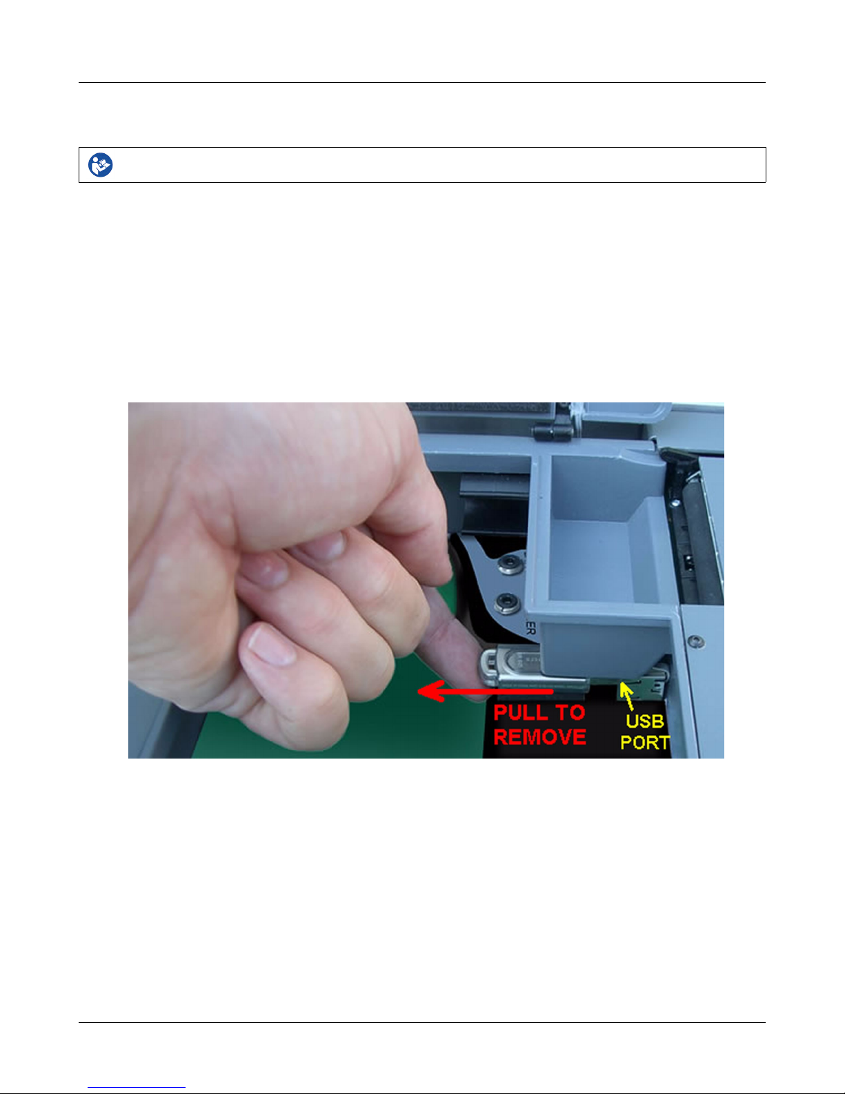
The system USB flash drive is located in the test chamber under the printer paper roll cradle.
To view the User's Guide:
5. Turn the RM500SL off, open the test chamber and remove the foam from the test chamber floor.
6. Gently remove the system USB flash drive from the USB port.
7. Insert the system USB flash drive into a USB port on your PC.
8. If your PC does not open the flash drive automatically, select My Computer, then the Removable Disk drive..
9. Double click the User_Guide folder to open it.
10. Double click the english folder and copy the RM500SL Users Guide.pdf file to an appropriate location on
your PC. Double click on the file to open it for viewing.
11. hen you have finished copying the file from the USB flash drive, click on the safely remove icon on your
PC and remove the flash drive when you are notified that it is safe to do so.
12. Reinstall the USB flash drive in the RM500SL making sure it is correctly and firmly in place.
12

RM500SL®User's Guide Version 3.16
October 2016
How to Avoid Undesirable Side Effects
During the development of the hearing aid analyzer, Audioscan performed a rigorous Risk Assessment to
identify any undesirable side effects that a user could be exposed to during the use of the RM500SL, and
incorporated numerous risk reduction design elements into the RM500SL to minimize the risk to users and
patients.
Following are the actions which a user should take to ensure that these risk control measures continue to be
effective
Loud Sounds:
The RM500SL is designed to produce sound pressure levels as high as 85 dB at the probe reference microphone.
Exposure to these levels for more than 7 hours can produce hearing damage. hen such levels are amplified by
a hearing aid, the level in the ear canal will be determined by the settings of the hearing aid but may reach levels
that can produce hearing damage in less than 30 seconds. To avoid this possibility,
1. hearing aids should be adjusted to limit sound pressure levels to safe levels
2. the maximum TM SPL setting (see Max TM SPL Setup) should be used to terminate tests if an unsafe level
is detected in the ear canal
3. test levels should be limited to 70 dB SPL except when necessary to verify the limiting levels of the hearing
aid, in which case, the test should not last longer than 15 seconds
4. be aware of the test signal and patient reaction during a test and be prepared to respond to any sign of
discomfort by reducing the SPL setting, switching off the equipment or the hearing aid, or removing the
patient from the area.
hen using the equipment to measure the Real-Ear to Coupler Difference in small ear canals, it is possible to
induce a hearing loss if the test is allowed to continue for more than 1 hour. Since accurate results can be
obtained in less than 10 seconds, this possibility should never occur in normal practice.
Power and Grounding:
This product contains numerous safety features to ensure that the probability of electrical shock is as low as
reasonably practicable. In order to ensure that all of the safety features work optimally you must ensure that the
power cord is plugged into a grounded outlet. Any line-powered peripherals connected to the RM500SL must
comply with UL/IEC 60601-1 OR comply with UL or IEC or ISO safety standards for such equipment, AND a)
be operated from an isolating transformer complying with UL/IEC 60601-1, OR b) be kept at least 6 feet (1.8m)
from the patient.
Ear Infection:
Probe tubes or RECD foam tips should not be re-used on another patient. There is a possibility of transferring an
ear infection to the other patient. Probe tubes and RECD foam tips are for single-patient use only. Do not
attempt to clean or re-use.
Ear Canal Discomfort:
An otoscopic examination should always be performed prior to inserting a probe tube into the ear canal to ensure
that it is healthy and free of obstructions. Care is needed when inserting probe tubes into the ear canal. Although
the probe tubes are made of soft, flexible material specially designed for this application, it is possible to scrape
the ear canal or touch the eardrum causing brief discomfort. You should carefully follow the instructions in
“Positioning the probe tube” section of this User’s Guide.
13
RM500SL®User's Guide Version 3.16
October 2016
2 Getting Started
This section provides instructions for unpacking the RM500SL and connecting various components and
associated items. Note that battery pills (SL-110), the RECD transducer (SL-100), the barcode scanner (VA-120)
and a microphone extension cable (VA-131, VA133) are associated items which must be ordered separately.
Unpacking and connecting
WARNING: To avoid the risk of electrical shock, use only the power cord supplied with the RM500SL and
connect it only to a grounded (protectively earthed) electrical outlet.
WARNING: To allow electrical power to be rapidly disconnected in the event of an emergency, position the
RM500SL in an accessible location so that the power cord may be quickly disconnected.
WARNING: To ensure that the operation of this product is not affected by EMC emissions from other
products, this product should not be used adjacent to or stacked on other equipment. If this is necessary, its
operation should be verified as normal in this configuration. Portable and mobile RF communications
equipment can affect the performance of this product
Failure to follow operating instructions could place the user or operator at risk.
1. Carefully unpack the RM500SL and check the contents of the shipping box against the enclosed packing list.
Note that some parts may be packed inside the test chamber.
2. Unwrap the power cord from its stowage hooks - noting carefully how it has been packed. To avoid serious
damage to the display screen, always repack the cord this way.
3. Connect the power cord to the socket next to the power switch on the right side of the unit. Plug the other end
into a grounded 100 – 240 volt power outlet.
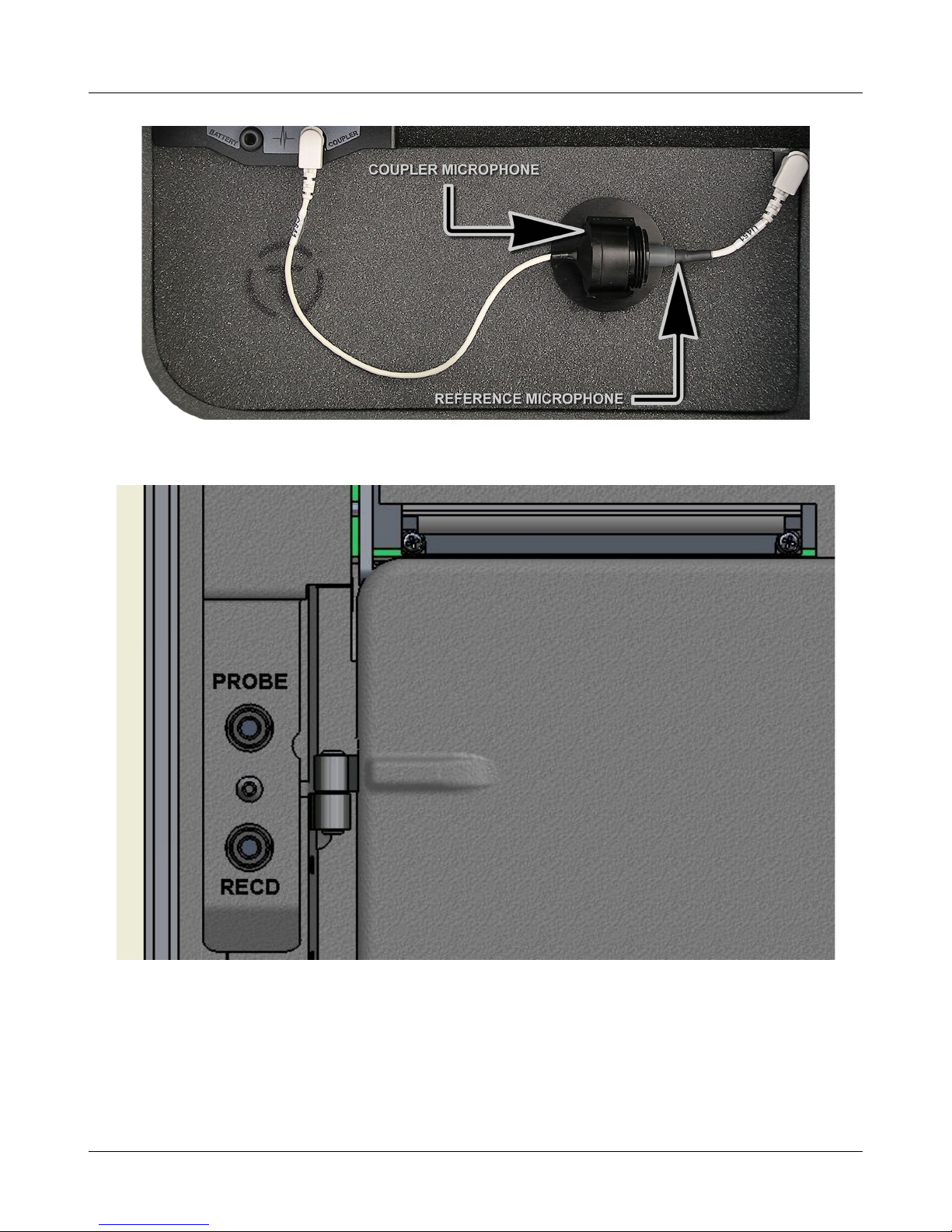
Microphone connection
1. Plug the reference microphone and the coupler microphone into the connectors in the test chamber as shown.
14
RM500SL®User's Guide Version 3.16
October 2016
2. Plug the probe microphone assembly into the probe connector located at the left of the test chamber as
shown.
NOTE: A microphone extension cable (VA-131, 133) is available from Audioscan. Standard audio extension
cables should not be used. They will substantially increase noise levels.
General care instructions
Probe tubes are for single patient use only. They may be wiped with alcohol wipes for re-use with the same
15

RM500SL®User's Guide Version 3.16
October 2016
patient, but must not be used with multiple patients. Attempts at ultrasonic cleaning usually result in cerumen
becoming lodged in the lateral end which causes irreparable damage to the probe microphones.
The case can normally be cleaned/dusted with a damp cloth, however if it is soiled we recommend wiping with a
mild solution of water and detergent, or with alcohol-impregnated wipes deemed safe for use on electronic
equipment. Parts that come into contact with patients (the probe module body, cable, and blue lanyard) should be
regularly wiped down with alcohol wipes.
Hearing instruments should be cleaned prior to introduction to the test chamber due to the difficulty of sanitizing
the acoustic foam. Custom hearing instruments must be cleaned with disinfectant towlettes (i.e. audiowipes)
prior to placing in the test for this reason and to minimize contamination of the blue putty used with the HA-1
coupler. The acoustic foam in the floor of the test chamber is easily removed and should be replaced if badly
worn or soiled.
Audioscan recommends periodic replacement of the blue putty used with the HA-1 coupler to ensure cleanliness.
Both couplers and coupler mic can be wiped down with alcohol wipes as needed.
Ensure that all safety and usage recommendations on cleaning product packages are followed.
Microphone care
Coupler microphone:
1. DO NOT twist the cable when attaching a coupler to the coupler microphone. Turn only the coupler or
unplug the coupler microphone before turning it.
2. DO NOT leave the coupler microphone plugged in when transporting.
3. DO make sure that the 2cc coupler is tightly screwed to the coupler microphone when performing hearing
instrument tests. Coupler leakage can cause feedback and erratic response curves.
4. DO make sure the tubing on the BTE (HA-2) coupler is free from any cracks/tears.
5. DO make sure that any replacement tubing used on the BTE coupler is either obtained from Audioscan, or is
#13 heavy wall earmold tubing exactly 10 mm in length.
Pro e microphone:
Debris can alter the probe module reference microphone calibration and frequency response and can
permanently clog the probe module port.
1. DO NOT reuse probe tubes. Probe tubes can be wiped with alcohol wipes for re-use with the same patient,
but must not be used with multiple patients. Attempts at ultrasonic cleaning usually result in cerumen
becoming lodged in the lateral end which causes irreparable damage to the probe microphones.
2. DO NOT attempt to open or repair the probe microphone. Attempting to repair the probe module may lead
to damage or alteration of the factory calibration.
3. DO keep the probe module and probe tubes in a clean area.
4. DO stow the probe module when not in use or when transporting the RM500SL.
Battery pill use and care
Battery pills are optional. The thin connecting strip of each battery pill is fragile. hen inserting pills into
hearing instrument battery compartments, take care that this strip is not pinched or bent severely as the battery
door is closed.
16

RM500SL®User's Guide Version 3.16
October 2016
1. Select a battery pill that is appropriately sized for the hearing instrument that you are testing.
2. Insert the pill into the hearing instrument, carefully closing the battery door over the thin connecting strip.
3. Plug the pill’s cable into the battery pill jack inside the RM500SL Test box. (to the left of the coupler
microphone connection).
4. Turn the hearing instrument on.
Mouse, keyboard, barcode scanner
WARNING: To avoid the risk of electrical shock, any line-powered peripheral equipment connected to this
product must comply with UL/IEC 60601-1 OR comply with UL or IEC and ISO safety standards for such
equipment AND a) be operated from an isolating transformer complying with UL/IEC 6061-1 OR b) be kept
at least 6 feet (1.8 m) from the patient.
Failure to follow operating instructions could place the user or operator at risk.
The RM500SL may be operated from the built-in keypad, a USB mouse (not included) or a standard USB
computer (Q ERTY) keyboard (not included), which may also be used to enter headers and comments on
printouts: See Input device operation.
An optional barcode scanner may be connected to the USB port to enter threshold, UCL and RECD data directly
from Audioscan printouts. Barcoded threshold data printed by some Grason-Stadler audiometric equipment may
also be scanned. Scanners other than that supplied by Audioscan may not work and are not supported by
Audioscan.
Multiple USB devices may be used together by connecting them to the RM500SL USB port via a USB hub.
17

RM500SL®User's Guide Version 3.16
October 2016
Auxiliary audio output jacks are not active in this version of software. Serial numbers below A2051 also have
an RS232 serial port which is not active in this version of software.
An external printer may be connected to the the USB port. It may be color or black & white but it must be PCL3,
PCL5 or PostScript compatible. The external printer must first be selected in Setup. See Printing and Storing
Results
18

RM500SL®User's Guide Version 3.16
October 2016
3 General Operation
This section describes the use of the built-in keypad, a Q ERTY keyboard (not included) or a computer mouse
(not included) to control the RM500SL and enter data. It also describes the use of an (optional) barcode scanner
to enter data from printouts produced by Audioscan analyzers and provides instructions for updating the
RM500SL operating software.
Input device operation
Failure to follow operating instructions could place the user or operator at risk.
The RM500SL may be operated by means of the built-in keypad, an external mouse or an external Q ERTY
keyboard. These devices are used to summon on-screen menus and select items from them, to operate on-screen
buttons and to input data. The scroll wheel on this type of mouse will scroll through long lists in list boxes and in
Help. Clicking the right mouse button generates an image of the keypad which may be operated by the mouse.
Clicking the left mouse button when the mouse pointer is on a graph will display a screen cursor with a digital
readout of X and Y co-ordinates. Clicking again will dismiss the cursor. Note that mouse speed can be changed
by selecting Setup and Display.
Function Keypad QWERTY ouse
Summon Help menu <Help> F1 Right click
Summon Setup menu <Setup> F2 Right click
Summon Test menu <Tests> F3 Right click
Summon Session menu <Session> F4 Right click
Switch between Ears or
A/B Data or Help index and Help page
<Left/Right> F5 Left click or Right click
for keypad image
Print <Print> Print Scrn Right click
Move across screen columns
Arrows Arrows
Move mouse
Move within a screen column Arrows Arrows Move mouse
Select a highlighted item or operate a
screen button
Round key (<PICK>
key)
Numeric
Enter Key
Left click
Enter numeric data Select point on chart Numeric
keypad
Left click on a point on
chart
Enter text Not possible Any key Not possible
Proceed from current state <Continue> Enter ↵Click Continue
Revert to previous state <Cancel> Esc Click Cancel
Barcode data input
Failure to follow operating instructions could place the user or operator at risk.
In Speechmap and Insertion gain tests, audiometric data in barcode form on an Audioscan analyzer printout may
1

RM500SL®User's Guide Version 3.16
October 2016
be entered by scanning the appropriate barcode. In Speechmap, air and bone threshold, UCL, RECD,
audiometric transducer, age and ABR nHL to eHL conversion factors are encoded. In Insertion gain, threshold
and transducer type are encoded. The type of data and the ear (left, right) is shown below the barcode. Only data
for the displayed ear are imported. Barcodes may be scanned in any order and it does not matter if the barcode is
'upside down'.
1. Select Speechmap or Insertion Gain from the Tests menu.
2. Hold the printout so that the barcode is flat. ith the scanner 6 – 8 in. (15 – 20 cm) from the barcode, press
the trigger on the scanner and center the illuminated red line along the length of the barcode.
3. hen the scan is successful, the scanner will 'beep', the red line will extinguish and a Barcode Entry poster
will appear on the screen. A green checkmark on the poster shows which data have been accepted. A
message will advise if the barcode does not contain data for the screen you are viewing.
4. hen all desired data have been accepted, select [Done] to apply the data.
See Barcodes, tabular data, headers and comments on printouts under Printing and Storing Results.
Keypad keys
20
Other manuals for RM500SL
2
Table of contents
Popular Test Equipment manuals by other brands

Tektronix
Tektronix TDS 520B Service manual

Cirris
Cirris 4200 Series quick start guide

Tamson Instruments
Tamson Instruments TV12 user manual

Baker Instrument Company
Baker Instrument Company D6000 DIGITAL TROUBLESHOOTING PROCEDURES & FAULT LISTING

Wiltron
Wiltron 67 B Series Maintenance manual

Tektronix
Tektronix TDS 510A instruction manual


