Tamson Instruments TV12 User manual

van 't Hoffstraat 12
2665 JL Bleiswijk, The Netherlands
T. 31 (0) 10 522 43 73
tv12-man Rev 2.0 UK 1017
Tamson Instruments bv
Page 1/29
ISO 9001 : 2015
NL/PRO 238239125
VAT: NL 80 66 34 984 B01
Bank account no.:
NL28 INGB 0007 350 370
NL95 RABO 0160100046
Chamber of commerce 27 16 95 41
USER-
MANUAL
TV12

van 't Hoffstraat 12
2665 JL Bleiswijk, The Netherlands
T. 31 (0) 10 522 43 73
tv12-man Rev 2.0 UK 1017
Tamson Instruments bv
Page 2/29
ISO 9001 : 2015
NL/PRO 238239125
VAT: NL 80 66 34 984 B01
Bank account no.:
NL28 INGB 0007 350 370
NL95 RABO 0160100046
Chamber of commerce 27 16 95 41
1SAFETY AND WARNINGS ......................................................................................................................3
2WARRANTY .............................................................................................................................................3
3PRECAUTIONS AND HAZARDS ............................................................................................................4
4INSTALLATION........................................................................................................................................4
4.1 IMPORTANT..........................................................................................................................................4
4.2 UNPACKING .........................................................................................................................................4
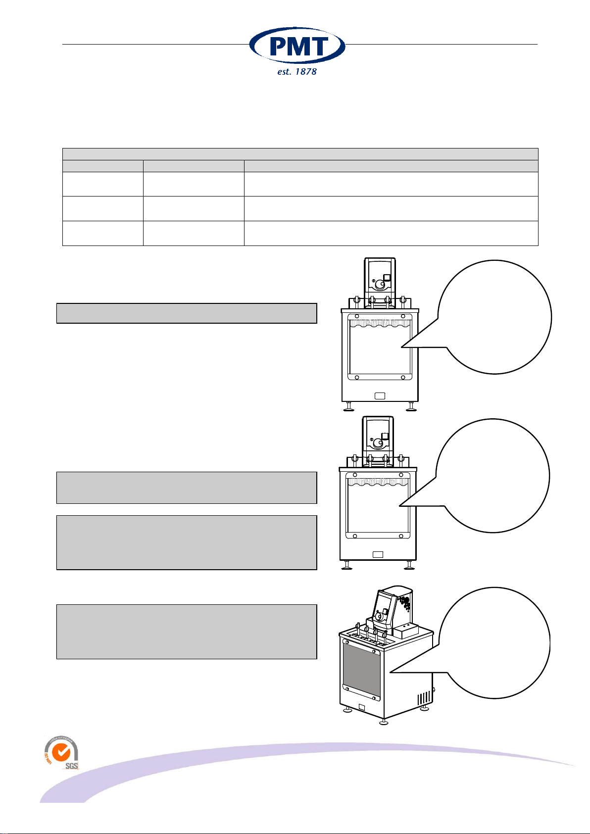
4.3 BATH LIQUID.........................................................................................................................................6
4.4 DRAIN BATH FLUID................................................................................................................................6
4.5 BATH FLUID LEVEL................................................................................................................................7
4.6 BATH FLUIDS........................................................................................................................................9
5COOLING................................................................................................................................................12
5.1 CONNECTING .....................................................................................................................................12
6INTRODUCTION.....................................................................................................................................13
6.1 GENERAL...........................................................................................................................................13
6.2 CONSTRUCTION .................................................................................................................................13
6.3 STIRRER............................................................................................................................................13
6.4 TEMPERATURE CONTROL AND SETTING................................................................................................13
6.5 SAFETY SYSTEMS...............................................................................................................................14
6.6 ADJUSTING THE MECHANICAL OVER-TEMPERATURE PROTECTION THERMOSTAT .....................................14
6.7 FRONT PANEL....................................................................................................................................14
6.8 OVERVIEW MENU ITEMS......................................................................................................................15
6.9 SAFETY THERMOSTAT.........................................................................................................................15
6.10 DISPLAY.........................................................................................................................................16
7OPERATING THE SYSTEM...................................................................................................................17
7.1 QUICK START.................................................................................................................................17
8MENU ITEMS..........................................................................................................................................17
8.1 PID SETTINGS....................................................................................................................................20
8.2 MANUAL TUNING.................................................................................................................................21
8.3 PRECISION OF CONTROL.....................................................................................................................22
8.4 LONG TERM STABILITY ........................................................................................................................22
8.5 HOMOGENEITY AND T.......................................................................................................................24
9RS232 COMMANDS...............................................................................................................................25
10 TROUBLE SHOOTING.......................................................................................................................25
10.1 APPLICATION ERRORS.....................................................................................................................25
10.2 BATH MALFUNCTION........................................................................................................................25
10.3 PROBLEMS WITH SET POINT.............................................................................................................25
10.4 FAULTY TEMPERATURE READING OR TEMPERATURE OFFSET .............................................................25
10.5 BATH TEMPERATURE DOES NOT BECOME STABLE .............................................................................26
10.6 BATH DOESN'T REACH SP...............................................................................................................26
11 SPARE PARTS LIST ..........................................................................................................................27
12 DIMENSIONS......................................................................................................................................27
13 EC DECLARATION OF CONFORMITY.............................................................................................28
14 DISCLAIMER ......................................................................................................................................29

van 't Hoffstraat 12
2665 JL Bleiswijk, The Netherlands
T. 31 (0) 10 522 43 73
tv12-man Rev 2.0 UK 1017
Tamson Instruments bv
Page 3/29
ISO 9001 : 2015
NL/PRO 238239125
VAT: NL 80 66 34 984 B01
Bank account no.:
NL28 INGB 0007 350 370
NL95 RABO 0160100046
Chamber of commerce 27 16 95 41
1 SAFETY AND WARNINGS
Make sure before installing or operating the equipment to read and understand all instructions and safety
precautions listed in this manual. If there are any questions concerning the operation of the equipment or
about the information given in this manual, please contact your local dealer or our sales department first.
Performance of installation, operation, or maintenance other than those described in this manual may result
in a hazardous situation and may void the manufacturer's warranty.
Never operate equipment that is not correctly installed. Unqualified personnel must not operate the
equipment. Avoid damage to the equipment, or its accessories, caused by incorrect operation.
Important:
-When performing service, maintenance or moving the apparatus, always disconnect the apparatus
at the mains socket,
-Proper skilled and trained personnel are only allowed to operate this equipment,
-Take notice of warning labels and never remove them,
-Refer service and repairs to qualified technician,
-If a problem persists, call your supplier or Tamson Instruments b.v.
2 WARRANTY
Tamson Instruments b.v. warrants that all their manufactured equipment is free from defects in material and
workmanship, preventing the machine from normal operation. Tamson Instruments b.v does not warranty that
the equipment is fit for any other use than stated in this manual. The manufacturer can only be held
responsible for the security, reliability and performance of the equipment, when operated in accordance with
the operating instructions, extensions, adjustments, changes and/or if repair is performed by Tamson
Instruments b.v. or authorized persons only. This warranty is limited to one year from the date of invoicing.
All equipment and materials are subject to standard production tolerances and variations.

van 't Hoffstraat 12
2665 JL Bleiswijk, The Netherlands
T. 31 (0) 10 522 43 73
tv12-man Rev 2.0 UK 1017
Tamson Instruments bv
Page 4/29
ISO 9001 : 2015
NL/PRO 238239125
VAT: NL 80 66 34 984 B01
Bank account no.:
NL28 INGB 0007 350 370
NL95 RABO 0160100046
Chamber of commerce 27 16 95 41
3 PRECAUTIONS AND HAZARDS
Before attempting to operate the bath read all parts
of this manual carefully to insure smooth operation
and avoid damage to the equipment or its
accessories.
If a malfunction occurs, consult section "Trouble
Shooting”, page 24 at the end of this manual.
If problem persists, call your supplier or Tamson
Instruments bv. Never operate the equipment if not
correctly installed. The equipment must be operated only
by qualified personnel. Avoid damage to the equipment
or its accessories through incorrect operation.
Environment
Panel sealing
Confirms EN60529: IP65
Environment Temperature
0 tot 35°C. Supply enough ventilation
Humidity
5 tot 95 %, non condensating
Atmosphere
Not suited for altitudes above 2000m
or
explosive/corrosive environment
Pollution cat. 2
Conducting pollution must be prevented
4 INSTALLATION
4.1 Important
Tamson Instruments bv is not responsible for any
consequential damage or harm caused by using this
bath. Repairs on the electrical system of the bath may
only be carried out by well trained and authorized
persons.
4.2 Unpacking
Before leaving the factory Tamson baths are adequately
packed to prevent damage during normal transportation.
Check the packing for external damage and make a note
on the shipping documents if any damage is found.
Always retain the cartons and packing material until the
bath has been tested and found in good condition.
(Transport companies generally will not honor a claim for
damage if the respective packing material is not available
for examination).
The shipment contains at least the bath as mentioned in
the delivery checklist. Further the consignment might
contain one or more viscometers, individually packed in
small boxes with the calibration certificate included in the
box, as well as ASTM thermometers, thermometer
READ
CAREFULLY
REMOVE ALL
PACKAGE MATERIAL

van 't Hoffstraat 12
2665 JL Bleiswijk, The Netherlands
T. 31 (0) 10 522 43 73
tv12-man Rev 2.0 UK 1017
Tamson Instruments bv
Page 5/29
ISO 9001 : 2015
NL/PRO 238239125
VAT: NL 80 66 34 984 B01
Bank account no.:
NL28 INGB 0007 350 370
NL95 RABO 0160100046
Chamber of commerce 27 16 95 41
holders etc. Please see the packing list for details
concerning total contents of consignment.
Before filling the bath remove any remaining packing
material from its interior. The interior of the bath can
be accessed by taking off the lid on the top of the
bath.

van 't Hoffstraat 12
2665 JL Bleiswijk, The Netherlands
T. 31 (0) 10 522 43 73
tv12-man Rev 2.0 UK 1017
Tamson Instruments bv
Page 6/29
ISO 9001 : 2015
NL/PRO 238239125
VAT: NL 80 66 34 984 B01
Bank account no.:
NL28 INGB 0007 350 370
NL95 RABO 0160100046
Chamber of commerce 27 16 95 41
4.3 Bath liquid
The bath must be filled with a liquid suitable for the
minimum operating temperature.
It is very important to select a liquid with a viscosity
of less than 20 mm²/s. At working temperature (SP)
the viscosity must be below 10 mm²/s.
When using flamable bath liquid choose a flash point
well above the operating temperature.
The use of other liquids is allowed as long as the viscosity
of the fluid is low enough at the operating temperature.
The viscosity must be below 10 mm²/s. High viscosity will
result in poor stability as well as poor uniformity of the
bath.
The fluid flash point must be well above the maximum
operating temperature. Fluid must not be aggressive
when in contact with stainless steel 304, 316, glass or
brass and silicon sealing.
4.4 Drain bath fluid
The TV12 can be emptied via the drain tap located at the
backside of the apparatus. For safety reasons the tap can
only be opened when using a screwdriver. The thread
inside the tap is 3/8".
Take necessary precautions against fire hazard when
removing flamable bath fluid.
When removing bath fluid do not inhale toxic vapor.
Always use appropriate ventilation.
Handle old bath fluid as toxic waste.
Cool down bath fluid to ambient before removing.
VISCOCITY:
< 10 mm²/s
FLASH POINT:
> OPERATING
TEMP.
USE SCREWDRIVER
TO OPEN TAP
3/8" BSP inside thread

van 't Hoffstraat 12
2665 JL Bleiswijk, The Netherlands
T. 31 (0) 10 522 43 73
tv12-man Rev 2.0 UK 1017
Tamson Instruments bv
Page 7/29
ISO 9001 : 2015
NL/PRO 238239125
VAT: NL 80 66 34 984 B01
Bank account no.:
NL28 INGB 0007 350 370
NL95 RABO 0160100046
Chamber of commerce 27 16 95 41
4.5 Bath fluid level
Minimum level
The heating element must be fully covered by the bath
fluid. The heating element will be damaged when not fully
submerged in the bath fluid.
The practical minimum level is indicated below.
The level indicator(optional) will start to blink (blue light)
when the fluid level is too low.
Low fluid level
- Can cause fire when heater get's partially
exposed
- Will damage the heater
- Can cause toxic fumes
Minimum
level
Maximum
level
TV12 front view
Min. level
Heating
element
Overflow
Outlet
Backside
Max. level
TV12 inside

van 't Hoffstraat 12
2665 JL Bleiswijk, The Netherlands
T. 31 (0) 10 522 43 73
tv12-man Rev 2.0 UK 1017
Tamson Instruments bv
Page 8/29
ISO 9001 : 2015
NL/PRO 238239125
VAT: NL 80 66 34 984 B01
Bank account no.:
NL28 INGB 0007 350 370
NL95 RABO 0160100046
Chamber of commerce 27 16 95 41
Maximum level
If the fluid level is too high, it will leave the bath via the
overflow outlet (14mm outher diameter pipe). Prevent
fluid from the overflow outlet entering the backside of the
TV12. For this reason the overflow outlet must be
connected to a waste container.
When the bath is working at high temperatures, tubing
and waste container must be chemical resistant and able
to withstand high temperatures (>150°C / 302°F).
CONNECT
OUTLET
TO WASTE
CONTAINER
PREVENT OVERFLOW
TUBING AND CONTAINER:
CHEMICAL RESISTANT
WITHSTAND HIGH
TEMPERATURE

van 't Hoffstraat 12
2665 JL Bleiswijk, The Netherlands
T. 31 (0) 10 522 43 73
tv12-man Rev 2.0 UK 1017
Tamson Instruments bv
Page 9/29
ISO 9001 : 2015
NL/PRO 238239125
VAT: NL 80 66 34 984 B01
Bank account no.:
NL28 INGB 0007 350 370
NL95 RABO 0160100046
Chamber of commerce 27 16 95 41
4.6 Bath fluids
We recommend the use of oil with viscosity < 10 mm²/s
Recommended bath fluids
Range
Ordering code
Description
Ambient to
80C/176F
N.A.
Clean tap water
NOT DISTILLED
80..150C /
176..302F
00T0220 (20 litres)
Tamson mineral oil 150. Transparent, 20 mm²/s @ 80°C/176°F; 3
mm²/s @ 150°C/302°F; F.P. 200°C/392°F.
20..150C /
68..302F
08T0001 (gross 20
Kg = 20 ltrs)
Silicon oil 200-10, transparent. 10 mm²/s @ 25°C/77°F;10 mm²/s
@ 150°C/301°F. F.P. 211°C/411°F. Lifetime >2 years.
The oil used has a limited lifetime.
The type, brand and operating temperature mainly
determines lifetime. Spilling of sample may also reduce
lifetime, in some cases can start chemical reactions.
Silicon oil has the tendency to form gel, for this reason
silicon oil has to be replaced as soon as visible changes
are noticed like string forming. Within a few hours silicon
oil can transform itself into solid gel, which is very difficult
to remove. When not totally cleaned, very small pieces of
left over gel will catalyze new oil to form gel!
Do not use distilled water. This will cause serious
corrosion.
Only use water as a bath fluid below 80°C/176°F.
Working for a longer period with water at
temperatures above 80°C will damage the stirrer
bearings.
Using the bath for long periods at low temperatures
will cause condensation on the glass window
resulting in complete invisibility of material placed
inside the bath.
CHECK
EXPIRING DATE
OIL
AFTER LONG
PERIODS OF LOW
TEMPERATURES
VISIBILITY BECOMES
LESS
NO TEMPERATURE
> 80ºC
H2O

van 't Hoffstraat 12
2665 JL Bleiswijk, The Netherlands
T. 31 (0) 10 522 43 73
tv12-man Rev 2.0 UK 1017
Tamson Instruments bv
Page 10/29
ISO 9001 : 2015
NL/PRO 238239125
VAT: NL 80 66 34 984 B01
Bank account no.:
NL28 INGB 0007 350 370
NL95 RABO 0160100046
Chamber of commerce 27 16 95 41
When operating at high temperatures the lid (of the
bath), top plate and the window section of the bath
become very hot. Always use heat protective gloves.
Care must be taken when placing or re-moving
material from the bath.
Pay attention when removing hot fluid:
Use heat protective clothing and wear gloves and
safety glasses.
When changing the bath fluid from water to oil for
operating at temperatures above 80°C, completely
remove all the water from the bath. Small drops of
water may result in hazardous situations while
reheating the bath with oil.
Water and oil must at all times be kept separate within
the bath. Never mix oil and water in or around the bath.
WEAR PROTECTIVE
GLOVES , CLOTHING
AND EYE
PROTECTION.
WEAR HEAT
PROTECTIVE GLOVES

van 't Hoffstraat 12
2665 JL Bleiswijk, The Netherlands
T. 31 (0) 10 522 43 73
tv12-man Rev 2.0 UK 1017
Tamson Instruments bv
Page 11/29
ISO 9001 : 2015
NL/PRO 238239125
VAT: NL 80 66 34 984 B01
Bank account no.:
NL28 INGB 0007 350 370
NL95 RABO 0160100046
Chamber of commerce 27 16 95 41
Do not spill water in hot oil.
Never empty hot oil into a plastic container.
Heated bath fluid can cause toxic fumes. Take
preacutions and read material safety sheet if applicable.
Remove fumes from hot oil or bath medium. Use
fume cabinet or proper air ventilation
H2O
OIL

van 't Hoffstraat 12
2665 JL Bleiswijk, The Netherlands
T. 31 (0) 10 522 43 73
tv12-man Rev 2.0 UK 1017
Tamson Instruments bv
Page 12/29
ISO 9001 : 2015
NL/PRO 238239125
VAT: NL 80 66 34 984 B01
Bank account no.:
NL28 INGB 0007 350 370
NL95 RABO 0160100046
Chamber of commerce 27 16 95 41
5 Cooling
The bath is provided with an integral cooling coil.
Because of the friction-heat generated by the stirrer
mechanism the bath will heat-up slowly. The lowest
operating temperature at which the bath can be controlled
depends on the fluid used and the ambient temperature.
When operating at temperatures around or below
ambient it is necessary to pass a small amount of tap
water through the cooling coil. Generally the temperature
of the cooling coil water should be 5 degrees (or more)
below the desired operating temperature of the bath. To
operate around ambient temperature a flow of 1 to 2l/min.
is sufficient.
Instead of using tap water a Tamson cooling circulator
can be connected to the TV12 to provide cooling. The
TLC10-3 is our smallest circulator and well suited for this
purpose.
5.1 Connecting
Before plugging TV12 into the mains socket, make sure
the voltage of the bath corresponds to the local voltage.
Use a mains supply that is well earthed, clean of
interference and suitable for the acquired electrical
load of the bath.
CONNECTORS FOR
COOLING
(OUTSIDE DIAMETER 10MM)
CHECK VOLTAGE
USE WELL EARTHED MAINS
TLC10-3
COOLING CIRCULATOR

van 't Hoffstraat 12
2665 JL Bleiswijk, The Netherlands
T. 31 (0) 10 522 43 73
tv12-man Rev 2.0 UK 1017
Tamson Instruments bv
Page 13/29
ISO 9001 : 2015
NL/PRO 238239125
VAT: NL 80 66 34 984 B01
Bank account no.:
NL28 INGB 0007 350 370
NL95 RABO 0160100046
Chamber of commerce 27 16 95 41
6 INTRODUCTION
The TAMSON model TV12 bath is designed to perform
as ultra stable visability bath. The intende use is
kinematic viscosity measurement and sensor calibration.
6.1 General
The heat input is controlled by a microprocessor system.
A special optimized electronic temperature measurement
circuit ensures reproducibility of operation conditions.
The bath has an integrated cooling coil as standard, for
rapidly reducing bath temperature alternatively for
working at or slightly below ambient temperature.
6.2 Construction
The TAMSON baths are constructed entirely from
corrosion-resistant materials –stainless steel and brass
–entirely. The central microprocessor within the control
module manages and controls the functions for
temperature measuring regulation, program storage,
safety control and error coding.
6.3 Stirrer
A circulation stirrer is built-in for uniform temperature
distribution within the bath.
6.4 Temperature control and setting
The bath temperature is regulated using a Pt-100
temperature probe Class A connected to a
microprocessor module. The advanced electronic control
system continually computes the energy input required
for optimal temperature accuracy and stability. The
controller will activate the heaters partially or in full,
depending on the difference between actual bath
temperature and set point, which also depends on the
type of bath fluid used and working conditions. This
process does not interfere electrically with other
equipment since all heating elements are switched in
zero-cross mode. Through the application of an
especially developed inlet circuit for the temperature
probe, the sensitivity to external interference has been
reduced to a minimum. The required temperature is set
by means of encoder switch on the front panel. An
absolute temperature offset is provided with a resolution
of 0.01°C. This fine-tuning can be carried out at any time
during operation of the bath.
1: On/off switch
2: Display
3: Indicator lights
4: Overtemperature cut-out
5: Encoder switch
6: Viscometer holders
1
2
3
4
5
6
1: RS232 connector (Sub D - female)
2: Motor fuse
3: Fan
4: Cooling coil (10mm outher diameter)
5: Overflow outlet (10mm outher diameter)
6: Mains connector (IEC60320)
(use well protected earth!)
7: Bath drain (3/8" inner thread)
4
1
2
3
5
6
7
4

van 't Hoffstraat 12
2665 JL Bleiswijk, The Netherlands
T. 31 (0) 10 522 43 73
tv12-man Rev 2.0 UK 1017
Tamson Instruments bv
Page 14/29
ISO 9001 : 2015
NL/PRO 238239125
VAT: NL 80 66 34 984 B01
Bank account no.:
NL28 INGB 0007 350 370
NL95 RABO 0160100046
Chamber of commerce 27 16 95 41
6.5 Safety systems
In case of electronic failure the possibility exists that the
heater element is continuously switched on. This will
cause extreme temperature raise. To prevent high
temperatures the bath is fitted with a mechanical over-
temperature protection thermostat. This thermostat will
switch-off the bath at a preset temperature in the range
from 50 to 270C.
We advise to adjust the mechanical over temperature
to approximately + 25C above the bath set point.
This safety construction prevents for example oil to be
heated above flaming-point which will cause fire or
prevent evaporation of bath fluid due to high
temperatures.
The thermostat will automatically reset when the bath
temperature drops approximately 10°C below the pre-set
temperature. To continue normal operation the bath has
to be switched off and on again.
6.6 Adjusting the mechanical over-tempe-
rature protection thermostat
Turn the thermostat clockwise (2, drawing 1) to its
maximum. Be aware that the safety thermostat is now
only functioning at 270 °C. Heat the bath to the
appropriate set point. Gently turn the thermostat anti-
clockwise, until the over-temperature protection is
activated, and system switches off, Turn the thermostat
approximately 30...40higher (turn clockwise). Switch
the bath off and on again. The bath is ready to operate
safely.
6.7 Front Panel
1 LC Display
2 Overtemperature indicator (Red)
3 Level indicator, optional (Blue)
4 Error (Yellow)
5 Heater indicators (Green)
6 Mains switch
7 Safety thermostat
8 Turn-push button
4
1
5
3
2
7
8
6

van 't Hoffstraat 12
2665 JL Bleiswijk, The Netherlands
T. 31 (0) 10 522 43 73
tv12-man Rev 2.0 UK 1017
Tamson Instruments bv
Page 15/29
ISO 9001 : 2015
NL/PRO 238239125
VAT: NL 80 66 34 984 B01
Bank account no.:
NL28 INGB 0007 350 370
NL95 RABO 0160100046
Chamber of commerce 27 16 95 41
The front panel layout shows the turn-push button:
Next / increase: Turn right
Previous / decrease: Turn left
Select: Press
6.8 Overview menu items
- Set point
- Offset (press: <-5.00 .. +5.00°C resolution 0.01°C)
- Max Power (press: low 25, med, hi, max)
- Boost heater (press on / off)
- Time const (press: fast, medium slow, precise)
- Stirrer
- Low alarm
- High alarm
- PID parameter :
PID set 1,
PID set 2,
PID set 3,
PID set 4.
Each PID set offers settings for
- Proportional band value
(Pb=1/P where P is proportional value)
- Integral value
- Differential value
- Backlight
- Temp units
- Baudrate
- SP Offset
- Restart
6.9 Safety thermostat
When the bath temperature becomes higher than the set
point temperature of the safety thermostat (Indicated as
7, see page 14), the heating electronics and controller are
switched-off. The red LED on the display will light. When
the temperature of the bath has been lowered with
approximately 10°C, the thermostat re-sets itself
automatically, however to continue normal operation the
bath has to be switched off and on again.
Use well grounded mains. Before plugging the TV12 into the mains socket, make sure the voltage of the bath
corresponds to the local voltage.

van 't Hoffstraat 12
2665 JL Bleiswijk, The Netherlands
T. 31 (0) 10 522 43 73
tv12-man Rev 2.0 UK 1017
Tamson Instruments bv
Page 16/29
ISO 9001 : 2015
NL/PRO 238239125
VAT: NL 80 66 34 984 B01
Bank account no.:
NL28 INGB 0007 350 370
NL95 RABO 0160100046
Chamber of commerce 27 16 95 41
6.10 Display
[1] Temperature readout
[2] Applied percentage of power
[3] Operating mode
[4] Indicator, alarm high, alarm low, control stable
Ad 1: When the controller starts or is restarted, the
displayed value increases to a stable readout appears
after a few seconds.
Ad 2: The controller calculates every second the
amount of power which should be applied for stable
control. The value is displayed with a resolution of 0.1%
and ranges from 0% to 99.9%.
Ad 3: Boost Bath is heating to set point using
boost heater
Heating Bath is heating to set point,
boostheater is off
Cooling Bath is cooling down to set point
Tuning Ratio Bath is tuning for power needed
at set point, first step
Tuning SA Bath is tuning, second step
PID SP=25.00 Bath is controlling, set point is
25.00°C (example)
Ad 4:
- Bath control is stable
- Alarm high, press button to reset*
- Alarm low, press button to reset*
* Optional item
1
3
2
4

van 't Hoffstraat 12
2665 JL Bleiswijk, The Netherlands
T. 31 (0) 10 522 43 73
tv12-man Rev 2.0 UK 1017
Tamson Instruments bv
Page 17/29
ISO 9001 : 2015
NL/PRO 238239125
VAT: NL 80 66 34 984 B01
Bank account no.:
NL28 INGB 0007 350 370
NL95 RABO 0160100046
Chamber of commerce 27 16 95 41
7 OPERATING THE SYSTEM
When the bath is ready for use it can be switched on by
pressing the mains switch.
The electronics are suited for both 50 and 60 Hz. Check
whether the voltage of the system conforms to the mains
voltage
7.1 QUICK START
To start operating the bath in a quick way do the
following:
Fill the bath with fluid as indicated in "Bath fluid level",
page 6,
Place the power plug, connect to mains socket,
Switch the bath on using the mains switch,
Select appropriate set point,
PID settings
All measuring results have been acquired using following
PID settings:
Pb := 25
I := 16
D := 0
Under different settings its possible to achieve even
better values by trimming the PID settings.
Place the bath spirit level. The four supporting feet can
be turned in and outwards for exact adjustment.
8 Menu items
Use the turn-push button to select a menu item and select
the item by pressing the button. After pressing a sign
appears next to the value indicating the value can now be
changed. Pressing the button again activates the value
immediately. When the value is altered but the button is
not pressed the value will be accepted and stored after 5
seconds automatically. The menu returns back to normal
operating mode.
Menu item "Set point"
Select the set point temperature. Resolution is 0.01°C +/-
the system accuracy.
Menu item "Offset"
The temperature displayed can be increased or decreased
with an offset ranging from +5.00 down to -5.00 °C in steps
of 0.01°C. This way the temperature reading on the display
can be synchronised with an independent separate
thermometer.
SPIRIT LEVEL

van 't Hoffstraat 12
2665 JL Bleiswijk, The Netherlands
T. 31 (0) 10 522 43 73
tv12-man Rev 2.0 UK 1017
Tamson Instruments bv
Page 18/29
ISO 9001 : 2015
NL/PRO 238239125
VAT: NL 80 66 34 984 B01
Bank account no.:
NL28 INGB 0007 350 370
NL95 RABO 0160100046
Chamber of commerce 27 16 95 41
Menu item "Max Power"
(press: low 25, med, hi, max)
Limits the applied power by a maximum value:
Low Maximum of 25% applied
Medium Maximum of 50% applied
High Maximum of 75% applied
Maximum 100% power is applied
Menu item "Boost heater"
A secondary heater is used to quickly heat up the bath. This
menu item enables or disables the heater.
Standard value: On
Menu item "Time const"
Used to select time to tune. The option precise has to be
used to reach maximum temperature accuracy. Options
are:
- Fast 60 seconds
- Medium 120 seconds
- Slow 180 seconds
- Precise 240 seconds
Standard value: Precise
Menu item "Stirrer"
Optional: Stirrer 0 .. 100% (step 6%). Inactive
Menu item "Low alarm"
Optional: min SP to max SP. resolution 0.1°C. No
hardware connected, display function only.
Menu item "High alarm"
Optional: min SP to max SP. resolution 0.1°C. No
hardware connected, display function only.
Menu item "PID parameter"
PID set 1 - First set of parameters
PID set 2 - Second set of parameters
PID set 3 - Third set of parameters
PID set 4 - Activated when communication
via RS232
Each set offers individual PID settings for:
Proportional band value
Integrating value
Differentiating value
Default settings
Pb* := 25
I := 16
D := 0
*Pb= proportional band. Proportional value P is found to be 100/Pb.
Menu item "Backlight"

van 't Hoffstraat 12
2665 JL Bleiswijk, The Netherlands
T. 31 (0) 10 522 43 73
tv12-man Rev 2.0 UK 1017
Tamson Instruments bv
Page 19/29
ISO 9001 : 2015
NL/PRO 238239125
VAT: NL 80 66 34 984 B01
Bank account no.:
NL28 INGB 0007 350 370
NL95 RABO 0160100046
Chamber of commerce 27 16 95 41
On
Off
Standard value: On
Menu item "Temp units"
°C
°F
Standard value: °C
Menu item "Baudrate"
300
600
1200
2400
4800
9600
19200
38400
Standard value: 9600
Menu item "Offset 0.005"
This menu item (optional) offers an additional offset of
0.005°C. The value of 0.005°C is added to the selected SP
value. The SP can be selected with 0.01°C accuracy.
Menu item "Restart"
Restarts system and activates tuning

van 't Hoffstraat 12
2665 JL Bleiswijk, The Netherlands
T. 31 (0) 10 522 43 73
tv12-man Rev 2.0 UK 1017
Tamson Instruments bv
Page 20/29
ISO 9001 : 2015
NL/PRO 238239125
VAT: NL 80 66 34 984 B01
Bank account no.:
NL28 INGB 0007 350 370
NL95 RABO 0160100046
Chamber of commerce 27 16 95 41
8.1 PID settings
Following shows influence on stability with different PID
settings
Temperature : 75°C
Proportional band (Pb) : 25
Integrator : 16
Differentiator : 0
Min/max : ± 0.015
Temperature : 75°C
Proportional band (Pb) : 50
Integrator : 25
Differentiator : 0
Min/max : ± 0.018°C
Temperature : 75°C
Proportional band (Pb) : 100
Integrator : 25
Differentiator : 0
Min/max : ± 0.045°C
SP 75°C
0.029
± 0.015
SP 75°C
0.036
± 0.018
SP 75°C
0.089
± 0.045
Table of contents
Popular Test Equipment manuals by other brands

Greenlee
Greenlee IPM-100 instruction manual

Milwaukee
Milwaukee pH51 user manual

Wolfgang Warmbier
Wolfgang Warmbier PGT 120 user manual

Fluke
Fluke NETWORK SERVICE MODULE DTX-NSM Getting started guide

Dräger
Dräger Alcotest 6810 GB Operator's instruction manual

Platinum Tools
Platinum Tools Fault Trapper TFT100 quick start guide

Elcometer
Elcometer 108 user guide

Hydac
Hydac FluidAqua Mobil FAM-200 Maintenance and Servicing Manual

Kusam-meco
Kusam-meco KM 720 Operation manual

Cal-Van Tools
Cal-Van Tools Amp Hound owner's manual

Johnson Controls
Johnson Controls Y99AW-1 Installation Sheets Manual

Sourcetronic
Sourcetronic TM-25R user guide