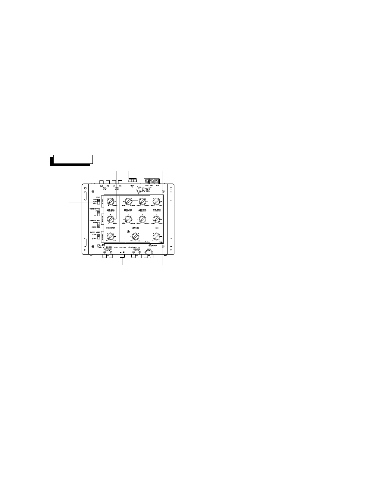
Audiovox Menace PX-300 User manual

Owner'sOwner's
Owner'sOwner's
Owner's
ManualManual
ManualManual
Manual
PX-300
2/3-Way Active
Crossover
BASS BOOST
+B dB @ 45Hz
ON OFF
30Hz
30Hz

INDEX
Specifications ................................................................................1
Installation Instructions .................................................................2
Wiring Instructions .........................................................................3
2-Way System Wiring Diagram ...........................................4 - 5
3-Way System Wiring Diagram ...........................................6 - 7
Operation ..............................................................................8 - 9
Warranty ...................................................................... Back Cover

HIGH PERFORMANCE 2/3-WAY ACTIVE CROSSOVER
This unit has been designed to provide high quality performance with a minimum of
maintenance. However,it'sperformancewillonlybeasgoodasthecareandquality
of components with which it is installed. We therefore advise that you read these
instructions very carefully to familiarize yourself with the product and it's features.
Should you require assistance with the installation or wiring of this unit, please call
our toll-free "HELP" line at 1-800-645-4994 during the days/hours shown.
Monday-Friday
Saturday
8:30am-7:00pmEastern
9:00am-5:00pmEastern
1-800-645-4994
-1-
SPECIFICATIONS
*Due to continuing improvement, Audiovox reserves the right to change features and design without notice.
FrequencyResponse: 10 - 50,000 Hz. ± 3 dB
Signal / Noise Ratio: 92dB(A-Weighted)
Distortion: 0.01%
InputImpedance: 10K ohms
Output Impedance: 100 ohms
Bass Boost: + 8 dB @ 45 Hz.
CrossoverSlope: 18 dB/octave
CrossoverFrequency
SubwooferLow-Pass: 30 - 500 Hz.
MidrangeHigh-Pass: 63 - 500 Hz.
MidrangeLow-Pass: 2,000 - 4,500 Hz.
HighHigh-Pass: 2,000 - 6,000 Hz.
Supply Voltage: 12 volts D.C., negative ground
Fuse Rating: 1 amp.
Dimensions (W x H x D): 8-1/4" x 1-1/4" x 7"
210 mm x 31 mm x 179 mm
HELP!

INSTALLATION INSTRUCTIONS
1. Select a mounting area where the crossover
will be accessible for occasional adjustment of
control settings.
2. Place the crossover on the mounting surface
and mark the locations of the four mounting
holes as shown in the illustration.
3. Remove the crossover and drill a 1/8" hole at
each of the four locations.
CAUTION: Before drilling the holes, look at the
underside of the mounting surface. Always
check carefully to avoid drilling into wiring,
braces, fuel or brake lines. CHECK BEFORE
YOU DRILL !
4. Secure the crossover to the mounting surface
using the self-tapping screws and washers
provided.
-2-
MOUNTING SURFACE
SELF-TAPPING SCREW
FLAT WASHER
INSTALLATION DIAGRAM
1/8" DIA.
HOLE
30Hz
30Hz

-3-
WIRING INSTRUCTIONS
The wiring of your crossover will depend on the system and speakers you are using but will either be a 2-way (bass and midrange/high) or 3-
way (bass, midrange and high) application using 2 or 4 channels of input from the car stereo. The following pages illustrate the input and output
wiring for these types. Please refer to the appropriate diagram for the system configuration you are using.
The power connections for this unit are made via screw tightened terminals. Loosen the screw for the connection to be made and fully insert
the wire (strip 1/2" of insulation from the end) under the respective screw on the side panel. Tighten the screw down to secure the wire.
1. Power Connection
The battery terminal (+12V) must be connected directly to the positive terminal of the vehicle battery to provide an adequate voltage source
and minimize noise. Connecting the battery terminal lead to any other point (such as the fuse block) may cause noise and distortion. Use
#18 gauge wire for this lead and connect it to the terminal of the battery after all other wiring is completed.
2. Ground Connection
The ground terminal (GND) connection is also critical to the correct operation of the crossover. Use a wire of the same gauge as the power
connection (#18) and connect it between the ground terminal (GND) of the unit and a metal part of the vehicle close to the mounting location.
This wire should be as short as possible and any paint or rust at the grounding point should be scraped away to provide a clean metal surface
to which the end of the ground wire can be screwed or bolted.
3. Remote Turn-On Connection
The crossover is turned on by applying +12 volts to the remote turn-on terminal (REM). The wire lead to this terminal should be connected
to the "Auto-Antenna" lead from the car stereo which will provide the +12 volts only when the car stereo is turned on. If the car stereo does
not provide an Auto-Antenna lead, the remote turn-on lead may be wired to an "Accessory" or "Radio" terminal in the car's fuse block. This
will turn the crossover on and off with the ignition key, regardless of whether the car stereo is on or off. The remote turn-on lead does not carry
large currents, so #20 gauge wire may be used for this application.
4. Input Connections
This crossover features low-level input capability. If the car stereo has 2 channels of low-level output, connect them to the "FRONT INPUT"
jacks (see pages 4 and 6). If the car stereo has 4 channels of low-level output, connect them to the "FRONT INPUT" and "REAR INPUT" jacks
(see pages 5 and 7).
5. Output Connections
Connect the low-level output jacks from the crossover to the low-level inputs of the amplifier(s) in the system. For 2-way systems, use the
"SUBWOOFER OUTPUT" and "MIDRANGE OUTPUT" jacks (see pages 4 and 5). For 3-way systems, use the "SUBWOOFER OUTPUT",
"MIDRANGE OUTPUT" and "HIGH OUTPUT" jacks (see pages 6 and 7).

CAR STEREO
-4-
2-WAY SYSTEM WIRING
USING 2 CHANNEL INPUT
LOW-LEVEL
RCA OUTPUTS
RIGHT
AUTO-ANTENNA
LEAD
LEFT
WOOFER
EXISTING SCREW OR BOLT
CLEAN PAINT, RUST, DIRT OR
GREASE FROM AREA FOR
GOOD CONNECTION
GROUNDED METAL
SECTION OF VEHICLE
12 VOLT
VEHICLE
BATTERY CHASSIS
GROUND
CONNECT THIS WIRE
LAST
2-CHANNEL
WOOFER AMPLIFIER
MIDRANGE / HIGH
AMPLIFIER
RIGHT
WOOFER
LEFT MIDRANGE/
TWEETER
RIGHT MIDRANGE/
TWEETER
LEFT
SET TO
"FRONT"
SET TO
"STEREO"
SET TO
"2-WAY"
OR
MONO
WOOFER
MONO
WOOFER AMPLIFIER
SET TO
"MONO"
BASS BOOST
+B dB @ 45Hz
ON OFF
30Hz
30Hz
30Hz

CAR STEREO
-4-
2-WAY SYSTEM WIRING
USING 4 CHANNEL INPUT
LOW-LEVEL
RCA OUTPUTS
AUTO-ANTENNA
LEAD
LEFT
WOOFER
EXISTING SCREW OR BOLT
CLEAN PAINT, RUST, DIRT OR
GREASE FROM AREA FOR
GOOD CONNECTION
GROUNDED METAL
SECTION OF VEHICLE
12 VOLT
VEHICLE
BATTERY CHASSIS
GROUND
CONNECT THIS WIRE
LAST
2-CHANNEL
WOOFER AMPLIFIER
MIDRANGE / HIGH
AMPLIFIER
RIGHT
WOOFER LEFT MIDRANGE/
TWEETER
RIGHT MIDRANGE/
TWEETER
RIGHT REAR
SET TO
"FRONT + REAR"
SET TO
"STEREO"
SET TO
"2-WAY"
OR
MONO
WOOFER
MONO
WOOFER AMPLIFIER
SET TO
"MONO"
LEFT REAR
RIGHT FRONT
LEFT FRONT
BASS BOOST
+B dB @ 45Hz
ON OFF
30Hz
30Hz
30Hz

CAR STEREO
-6-
3-WAY SYSTEM WIRING
USING 2 CHANNEL INPUT
LOW-LEVEL
RCA OUTPUTS
RIGHT
AUTO-ANTENNA
LEAD
LEFT
WOOFER
EXISTING SCREW OR BOLT
CLEAN PAINT, RUST, DIRT OR
GREASE FROM AREA FOR
GOOD CONNECTION
GROUNDED METAL
SECTION OF VEHICLE
12 VOLT
VEHICLE
BATTERY CHASSIS
GROUND
CONNECT THIS WIRE
LAST
2-CHANNEL
WOOFER AMPLIFIER
MIDRANGE
AMPLIFIER
RIGHT
WOOFER
LEFT
MIDRANGE
RIGHT
MIDRANGE
LEFT
SET TO
"FRONT"
SET TO
"STEREO"
SET TO
"3-WAY"
OR
MONO
WOOFER
MONO
WOOFER AMPLIFIER HIGH AMPLIFIER
LEFT
TWEETER
RIGHT
TWEETER
SET TO
"MONO"
BASS BOOST
+B dB @ 45Hz
ON OFF
30Hz
30Hz
30Hz

CAR STEREO
-7-
3-WAY SYSTEM WIRING
USING 4 CHANNEL INPUT
LOW-LEVEL
RCA OUTPUTS
AUTO-ANTENNA
LEAD
LEFT
WOOFER
EXISTING SCREW OR BOLT
CLEAN PAINT, RUST, DIRT OR
GREASE FROM AREA FOR
GOOD CONNECTION
GROUNDED METAL
SECTION OF VEHICLE
12 VOLT
VEHICLE
BATTERY CHASSIS
GROUND
CONNECT THIS WIRE
LAST
2-CHANNEL
WOOFER AMPLIFIER
MIDRANGE
AMPLIFIER
RIGHT
WOOFER
LEFT
MIDRANGE
RIGHT
MIDRANGE
SET TO
"FRONT + REAR"
SET TO
"STEREO"
SET TO
"3-WAY"
OR
MONO
WOOFER
MONO
WOOFER AMPLIFIER
SET TO
"MONO"
HIGH AMPLIFIER
LEFT
TWEETER
RIGHT
TWEETER
RIGHT REAR
LEFT REAR
RIGHT FRONT
LEFT FRONT
BASS BOOST
+B dB @ 45Hz
ON OFF
30Hz
30Hz
30Hz

-8-
OPERATION
1POWER INDICATOR
The Power Indicator LED will illuminate to indicate that the unit is
connected to the battery and that the Remote Turn-On terminal is
receiving +12 volts, thus turning on the crossover.
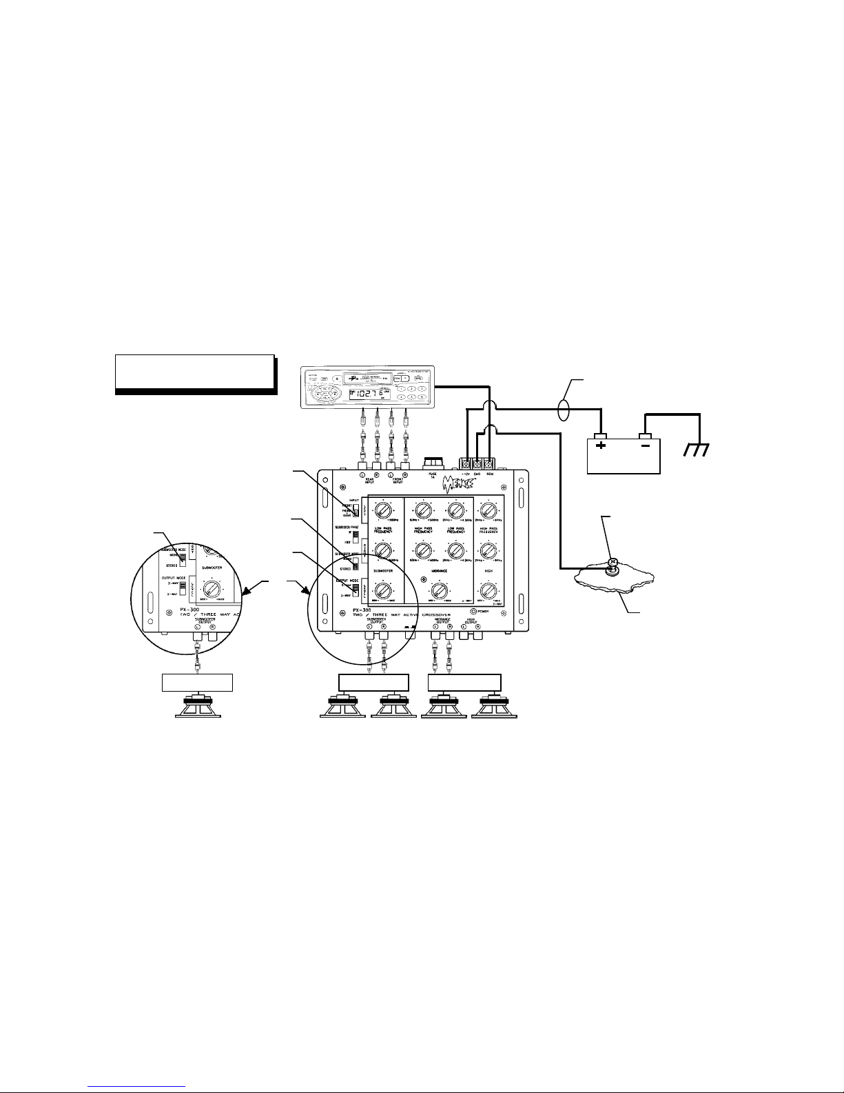
2INPUT SELECTOR
This switch is used to select the inputs of the audio signal to the crossover.
In the “FRONT” setting, only the input connected to the “FRONT INPUT”
jacks will be processed. In the “FRONT + REAR” setting, both the inputs
to the “FRONT INPUT” and “REAR INPUT” jacks will be processed.
NOTE: When set to the “FRONT + REAR” setting, the signal to the “REAR
INPUT” jacks is processed and adjusted by the Subwoofer Level
and Subwoofer Low-Pass Frequency Controls 7and bl. The
“FRONT INPUT” signal is processed by the Midrange Level and
Midrange High-Pass Frequency Controls 8and bmif the Output
Mode Selector 3is set to the “2-WAY” setting or by the Midrange
andHigh Level andFrequencyControls8,9,bm,bnand boifthe
Output Mode Selector 3 is set to the “3-WAY” setting.
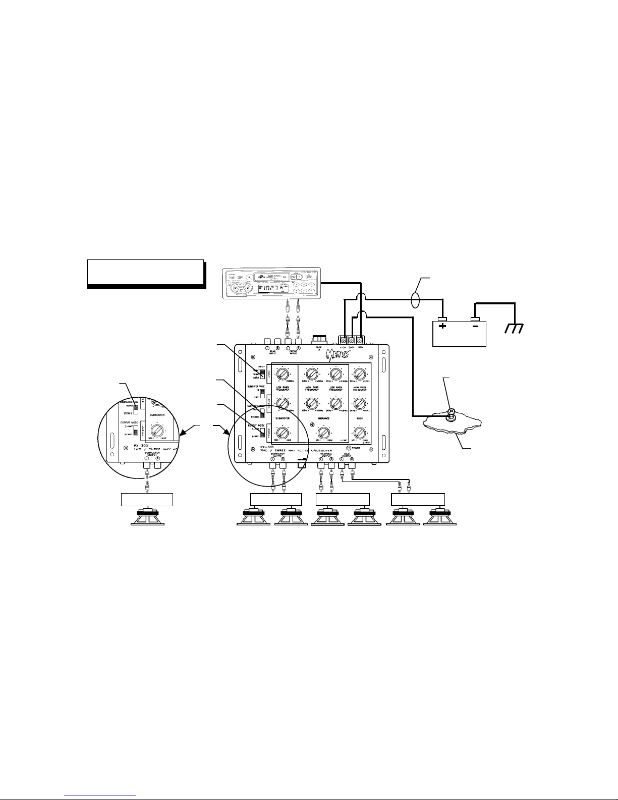
3OUTPUT MODE SELECTOR
This switch is used to select 2-Way or 3-Way operation of the crossover.
Set the switch to the appropriate position for the type of amplifier/speaker
system with which the crossover is being used.
In the “2-WAY” setting, the output from the crossover will be from the
“SUBWOOFER OUTPUT” and “MIDRANGE OUTPUT” jacks, and will be
adjusted by the Subwoofer and Midrange controls 7,8,bl and bm(the
High Frequency section controls 9and bo and the “HIGH OUTPUT”
jacks will be disabled).
In the “3-WAY” setting, the output from the crossover will be from the
“SUBWOOFER OUTPUT”, "MIDRANGE OUTPUT” and “HIGH OUTPUT”
jacks and all adjustment controls will be active.
4SUBWOOFER PHASE SELECTOR
This switch is used to adjust the phase of the “SUBWOOFER OUTPUT”
by 180°. Set the switch to the position that provides the smoothest bass
response with the speaker system being used.
5SUBWOOFER MODE SELECTOR
This switch is used to select Stereo or Mono subwoofer output. If the
speaker system uses 2 channels of low-frequency amplification and 2
woofers, set the switch to the “STEREO” position. If used with a single
channel of low-frequency amplification, set the switch to the “MONO” position.
6BASS BOOST SELECTOR
This switch is used to accentuate the bass frequencies by adding 8 dB
of boost to the signal at 45 Hz.
7SUBWOOFER LEVEL CONTROL
This control is used to adjust the output level from the “SUBWOOFER
OUTPUT” jacks. Set the control to the “MIN” position and slowly adjust
it until the desired level of subwoofer output is achieved for the amplifier/
speaker system being used.
2
6718
4
5
3
BASS BOOST
+B dB @ 45Hz
ON OFF
9
bmblbnbobp
30Hz
30Hz

-9-
8MIDRANGE LEVEL CONTROL
This control is used to adjust the output level from the “MIDRANGE
OUTPUT” jacks. Set the control to the “MIN” position and slowly adjust
it until the desired level of midrange output is achieved for the amplifier/
speaker system being used.
9HIGH LEVEL CONTROL
This control is used to adjust the output level from the “HIGH OUTPUT”
jacks. Set the control to the “MIN” position and slowly adjust it until the
desired level of high frequency output is achieved for the amplifier/
speaker system being used.
NOTE: The High Level Control is only operational in the “3-WAY” setting
of the Output Mode Selector 3. If the Output Mode Selector is in
the “2-WAY” setting, there will be no output from the “HIGH
OUTPUT” jacks and no effect by adjusting the High Level Control
9or High High-Pass Frequency Controls bo.
blSUBWOOFER LOW-PASS FREQUENCY CONTROLS
These controls (one each for the right and left channels) are used to set
the low-pass filter crossover frequency in the Subwoofer section of the
unit. The frequencies below the setting of these controls will be passed
through the crossover to the “SUBWOOFER OUTPUT” jacks. Adjust the
controls as appropriate for the woofer-to-midrange crossover frequency
of the speaker system being used.
bmMIDRANGEHIGH-PASSFREQUENCYCONTROLS
These controls (one each for the right and left channels) are used to set
the high-pass filter crossover frequency in the Midrange section of the
unit. The frequencies above the setting of these controls will be passed
through the crossover to the “MIDRANGE OUTPUT” jacks. Adjust the
controls as appropriate for the woofer-to-midrange crossover frequency
of the speaker system being used.
bnMIDRANGELOW-PASSFREQUENCYCONTROLS
These controls (one each for the right and left channels) are used to set
the low-pass filter crossover frequency in the Midrange section of the
unit when the Output Mode Selector 3is in the “3-WAY” setting. The
frequencies below the setting of these controls and above the setting
of the Midrange High-Pass Frequency Control bm will be passed
through the crossover to the “MIDRANGE OUTPUT” jacks. Adjust the
controls as appropriate for the midrange-to-tweeter crossover fre-
quency of the speaker system being used.
NOTE: In the “2-WAY” setting of the Output Mode Selector 3, the
Midrange Low-Pass Frequency Controls are disabled and all
frequencies above the setting of the Midrange High-Pass
Frequency Controls bmwill be passed through tothe“MIDRANGE
OUTPUT” jacks.
bo HIGHHIGH-PASSFREQUENCYCONTROLS
These controls (one each for the right and left channels) are used to set
the high-pass filter crossover frequency in the High Frequency section
of the unit when the Output Mode Selector 3is in the “3-WAY” setting.
The frequencies above the setting of the High High-Pass Frequency
Control will be passed through the crossover to the “HIGH OUTPUT”
jacks. Adjust the controls as appropriate for the midrange-to-tweeter
crossover frequency of the speaker system being used.
NOTE: The High High-Pass Controls are only operational in the “3-WAY”
setting of the Output Mode Selector 3. If the Output Mode
Selector is in the “2-WAY” setting, there will be no output from
the “HIGH OUTPUT” jacks and no effect by adjusting the High
Level Control 9or High High-Pass Frequency Controls bo.
bpFUSE
The circuitry of the crossover is protected from damage by an automo-
tive-type fast-blow fuse. If fuse replacement is necessary, use only
fuses of the same ampere rating (1 Amp.) as originally supplied with
the unit. The use of fuses with incorrect ratings may cause serious
damage to the crossover. If fuses blow consistently, carefully check all
electrical connections to the unit.

AUDIOVOX CORPORATION (the Company) warrants to the original retail purchaser of this product that should this product or any part
thereof, under normal use and conditions, be proven defective in material or workmanship within 12 months from the date of original purchase,
such defect(s) will be repaired or replaced with new or reconditioned product (at the Company's option) without charge for parts and repair
labor.
To obtain repair or replacement within the terms of this Warranty, the product is to be delivered with proof of warranty coverage (e.g. dated
bill of sale), specification of defect(s), transportation prepaid, to an approved warranty station or the Company at the address shown below.
This Warranty does not extend to the elimination of externally generated static or noise, to correction of antenna problems, to costs incurred
for installation, removal or reinstallation of the product, or to damage to tapes, compact discs, speakers, accessories, or vehicle electrical
systems.
This Warranty does not apply to any product or part thereof which, in the opinion of the Company, has suffered or been damaged through
alteration, improper installation, mishandling, misuse, neglect, accident, or by removal or defacement of the factory serial number/bar code
label(s). THE EXTENT OF THE COMPANY'S LIABILITY UNDER THIS WARRANTY IS LIMITED TO THE REPAIR OR REPLACEMENT
PROVIDED ABOVE AND, IN NO EVENT, SHALL THE COMPANY'S LIABILITY EXCEED THE PURCHASE PRICE PAID BY PURCHASER
FOR THE PRODUCT.
This Warranty is in lieu of all other express warranties or liabilities. ANY IMPLIED WARRANTIES, INCLUDING ANY IMPLIED WARRANTY
OF MERCHANTABILITY, SHALL BE LIMITED TO THE DURATION OF THIS WRITTEN WARRANTY. ANY ACTION FOR BREACH OF ANY
WARRANTY HEREUNDER INCLUDING ANY IMPLIED WARRANTY OF MERCHANTABILITY MUST BE BROUGHT WITHIN A PERIOD
OF 30 MONTHS FROM DATE OF ORIGINAL PURCHASE. IN NO CASE SHALL THE COMPANY BE LIABLE FOR ANY CONSEQUENTIAL
OR INCIDENTAL DAMAGES FOR BREACH OF THIS OR ANY OTHER WARRANTY, EXPRESS OR IMPLIED, WHATSOEVER. No person
or representative is authorized to assume for the Company any liability other than expressed herein in connection with the sale of this product.
Some states do not allow limitations on how long an implied warranty lasts or the exclusion or limitation of incidental or consequential damage
so the above limitations or exclusions may not apply to you. This Warranty gives you specific legal rights and you may also have other rights
which vary from state to state.
12 MONTH LIMITED WARRANTY
Applies to automotive radios, radio/tape players, radio/CD players,
CD changers, power amplifiers, equalizers and accessories.
Form. No. 128-5275
AUSTRALIA : AUDIOVOX PACIFIC PTY LTD., DOYLE AVENUE, UNANDERRA, NSW 2526 (042) 718-555
CANADA : CALL 1-800-645-4994 FOR LOCATION OF WARRANTY STATION SERVING YOUR AREA
U.S.A. : AUDIOVOX CORPORATION, 150 MARCUS BLVD., HAUPPAUGE, NEW YORK 11788 1-800-645-4994
NEW ZEALAND : AUDIOVOX PACIFIC PTY LTD., UNIT B, 6 HENDERSON PLACE, PENROSE, AUCKLAND (09) 645-720
© 1998 Audiovox Corporation Printed in Korea Form No. 128-5299A
Table of contents
Other Audiovox Crossover manuals