7 8
OPERATING INSTRUCTIONS
Once the vehicle accessory adapter is properly connected to a 12-Volt DC power source,
t h e b i - c o l o r L E D i n d i c a t o r l i g h t s G R E E N w h e n t h e i n v e r t e r i s
c o n n e c t e d t o D C p o w e r a n d t h e u n i t p o w e r i s O N . ( I f t h e
b i - c o l o r L E D i n d i c a t o r l i g h t s R E D , r e f e r t o t h e
"Troubleshooting" section on page 12 of this manual.)
ALWAYS TURN THE INVERTER ON BEFORE APPLYING
POWER TO THE DEVICE.
The standard North American 110/120 volt AC and USB
outlets allow the user to operate multiple devices
simultaneously. Simply plug the equipment into the unit.
Note: Ensure wattage of all equipment simultaneously
plugged into the power inverter does not exceed 120-
watts continuous.
Rated Versus Actual Current Draw of Equipment
Most electrical tools, appliances, electronic devices and
audio/visual equipment have labels that indicate the power
consumption in amps or watts. Be sure the power
consumption of the item to be operated is below 120-
watts. If the power consumption is rated in amps AC, simply
multiply by the AC volts (110/120) to determine the power.
Resistive loads are the easiest for the inverter to run;
however, it will not operate larger resistive loads (such as electric
stoves and heaters), which require far more wattage than
the inverter can deliver. Inductive loads (such as TVs and
stereos) require more current to operate than do resistive
loads of the same wattage rating.
For safety reasons, the inverter will simply shut down if it is
overloaded. To restart the unit, simply reinsert the12-Volt
vehicle accessory adapter to reset.
Operation of the 110/120 Volt AC Outlet
1.Connect the Power Cord to the inverter.
2.Connect either the 12-Volt DC Vehicle Accessory Adapter
or the 12-Volt DC Airplane Adapter to the end of the 12-
Volt Power Cord.
3.Insert the selected adapter Plug into a vehicle's (or other
12-Volt DC power source's) DC accessory outlet or airplane
DC power outlet.
4.Rotate the vehicle accessory plug slightly to make sure
there is good contact.
5.The LED in the inverter will light GREEN, indicating a proper
connection.
6.If the inverter does not work, make sure the ignition/
accessory switch is actually powering the accessory outlet.
Some vehicles require the ignition switch to be turned on.
7.Plug the (110/120 Volt AC) appliance into the inverter's
two or three-prong AC outlet and operate normally.
Note: The inverter will not operate appliances and
equipment that generate heat, such as hair dryers, electric
blankets, microwave ovens and toasters.
Operation of the USB Power Port
1.Connect the Power Cord to the inverter.
2.Connect either the 12-Volt DC Vehicle Accessory Adapter
or 12-Volt DC Airplane Adapter to the end of the 12-Volt
Power Cord.
All-in-One
User's Manual User's Manual User's Manual
3.Insert the selected adapter plug into a vehicle's (or jump-
starter's) DC accessory outlet or airplane DC power outlet.
4.Rotate the plug slightly to make sure there is good
contact.
5.The LED will light GREEN, indicating a proper connection.
6.If the inverter does not work, make sure the ignition/
accessory switch is actually powering the accessory outlet.
Some vehicles require the ignition switch to be turned on.
7.Plug the USB-powered device into the inverter's USB Power
Port and operate normally.
9
Notes:This inverter's USB Power Port does not support
data communication. It only provides 5 volts/500mA DC
power to an external USB-powered device.
The USB power output is not controlled by the ON/OFF Power.
The USB power is always on when the Power Cord is connected
to a 12-Volt DC power source. Remember to disconnect the
Power Cord from any power source when the unit is not in
use.
Protective Features
The inverter monitors the following conditions:
• Low Battery Voltage-This condition is harmful to the
inverter, and could damage the power source, so the
inverter will automatically shut down when input voltage
drops below 10.5 Volts DC.
• Input Voltage Too High-The inverter will automatically
shut down when DC input voltage exceeds 15 Volts, as
this can harm the unit.
• Thermal Shutdown Protection-The inverter will auto-
matically shut down when the unit becomes overheated.
10
• Overload/Short Circuit Protection-The inverter will auto-
matically shut down if a short circuit occurs.
• AC Ground Leakage-The inverter will automatically shut
down when leakage current exceeds a preset safety level.
Operating Tips
All-in-One
User's Manual
The All-in-one mobile power inverter should only be
operated in locations that are:
• DRY-Do not allow water or other liquids to come into
contact with the inverter.
• COOL-Surrounding air temperature should ideally be
0-40°C (32-104°F). Keep the inverter away from direct
sunlight, when possible.
• WELL-VENTILATED-Keep the area surrounding the inverter
clear to ensure free air circulation around the unit. Do not
place items on or over the inverter during operation. The
unit will shut down if the internal temperature gets too
hot.
• SAFE-Do not use the inverter near flammable materials or
in any locations that may accumulate flammable fumes or
gases. This is an electrical appliance that can briefly spark
when electrical connections are made or broken.
11 12
CARE AND MAINTENANCE
Storage
1.Ideal storage temperature range is 0-40°C (32-104°F).
2.Store and use the All-in-one mobile power inverter in
a cool, dry place with adequate ventilation for all-around
air circulation.
3.Avoid locations that are exposed to heating units,
radiators, direct sunlight, or excessive humidity or
dampness.
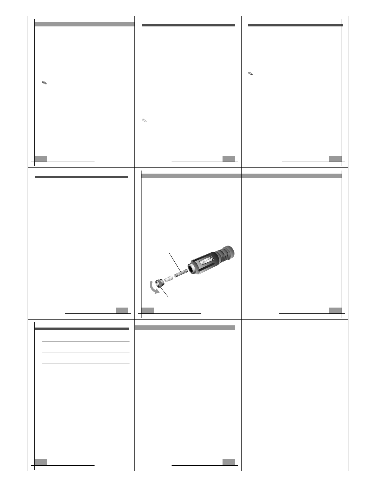
Fuse Replacement (in 12-Volt DC Power Cord)
1.Disconnect unit from 12-Volt DC power source.
2.Remove fuse cover from DC power wire cord. Remove
the fuse.
3.Replace with a new fuse (15 amp, glass type). Refer to
the illustration below.
TROUBLESHOOTING
Common Audio/Visual Problems
Problem: Buzzing Sound In Audio Systems
Some inexpensive stereo systems and boom boxes make a
buzzing sound when operated from the inverter, because
the power supply in the electronic device does not properly
filter the modified sine wave produced by the inverter. The
only solution to this problem is to use a sound system that
has a higher quality power supply.
The All-in-one mobile power inverter is shielded to
minimize interference with TV signals. However, in some
instances, some interference may still be visible, especially
when the TV signal is weak. Try the following to improve
the picture:
1.Move the 120 Watt Inverter as far away as possible from
the TV set, the antenna, and the antenna cables. Use a
short AC extension cord, if necessary.
2.Adjust the orientation of the antenna cables, and the TV
power cord to minimize interference.
3.Make sure that the antenna feeding the TV provides an
adequate (snow-free) signal and that high quality,
shielded antenna cable is used.
Fault LED Lights/Alert Buzzer Sounds
When the Power/Fault LED turns from GREEN (indicating the
unit is powered) to RED, a fault condition is present and the
unit will automatically shut down shortly. See "Protective
Features" on page 9 and "Common Power Output Problems"
below.
User's Manual User's Manual
REPLACEABLE FUSE 15AMP
Turn left to open the vehicle accessory adapter fuse cover.
9
All-in-One
128-8 232
13 User's Manual User's Manual 14
Common Power Output Problems
Possible Causes Recommendations
Battery voltage below
10.5 volts
Equipment being operated
draws too much power
Recharge battery or check
DC power supply.
Reduce load to maximum
120 watts.
Inverter in thermal
shutdown condition
Allow inverter to cool down.
Ensure there is adequate
ventilation around the unit,
and the load is no more than
120 watts for continuous
operation.
AC output is shorted Disconnect the AC appliance.
Pull out the DC Power Cord
from your vehicle's DC output.
Wait a few seconds and then
re-insert the DC Power Cord
to turn it back ON.
SPECIFICATIONS
All-in-One
Maximum Continuous Power................................120 Watts
Maximum Surge Capability (Peak Power)..............240 Watts
No Load Current Draw...............................................<0.3A
Waveform.............................................Modified Sine Wave
Operating Input Voltage Range....................11-15 Volts DC
AC Receptacle................110V/120V AC (3 prong grounded)
Approximate Dimensions................110L x 66W x 22 H/mm
4.33L x 2.5W x .8H/Inch
Approximate Weight.................................................123.2g
. 27lb