•
This inverter
is
an
electronic device
that
converts
low
voltage
DC
(direct current) electricity
from
abattery
to
110/120 Volt
AC
(alternating current) household power. In
designing this inverter, we have incorporated design
techniques previously employed in
computer
power
supplies.
This
result
of
these design innovations
is
asmaller,
lighter
and easier-to-use power inverter. The AII-in-one
mobile
power
inverter
converts power in
two
stages. The
first stage
is
aDC-to-DC conversion process
that
raises
the
low
voltage
DC
at
the inverter
input
to
145 volts
DC.
The
second
is
a
MOFSFET
bridge stage
that
converts the high
voltage
DC
into
110/120 volts, 60
Hz
AC.
AII-in-one
mobile
power
inverter
Output
Waveform
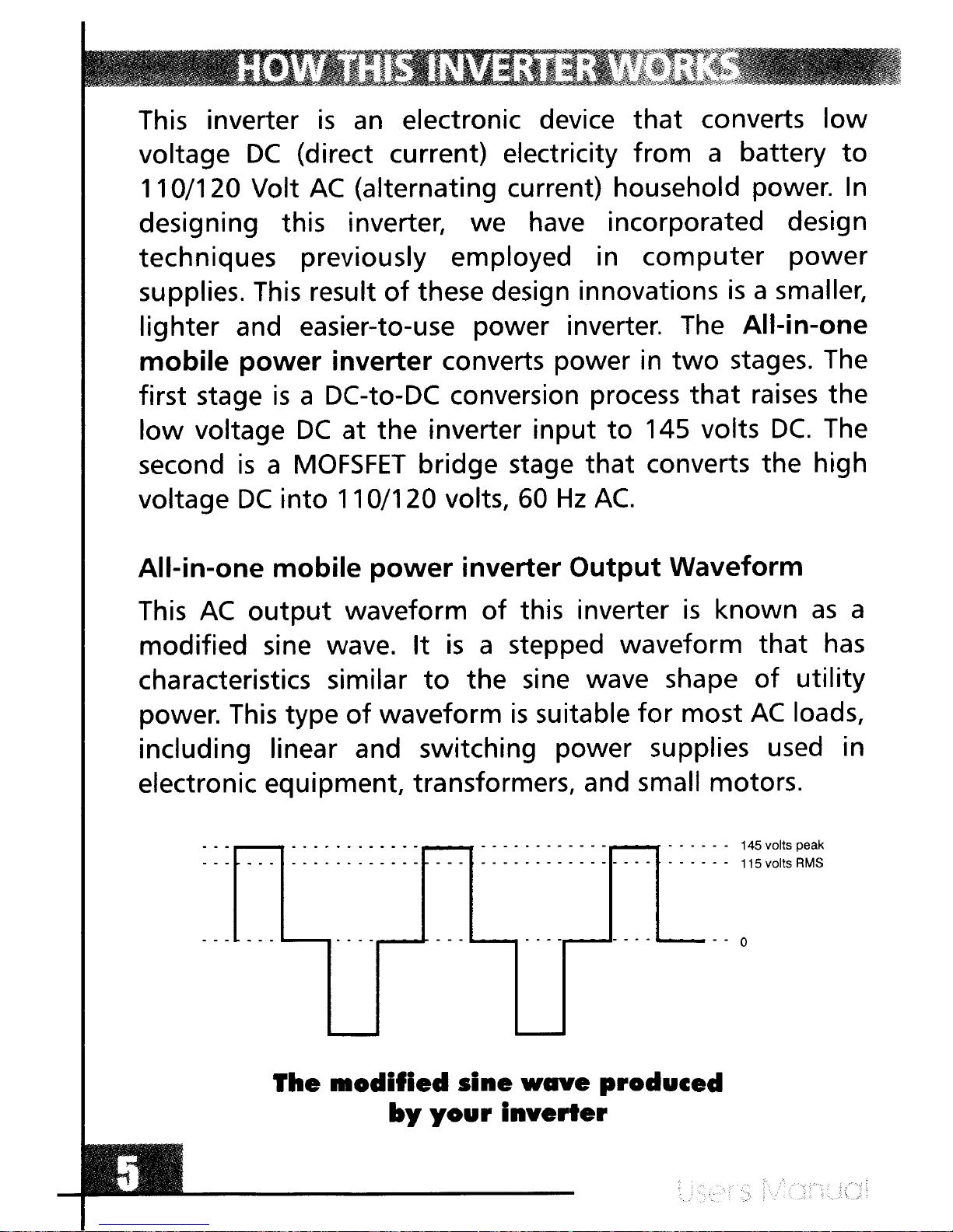
This
AC
output
waveform
of
this inverter
is
known
as
a
modified sine wave.
It
is
astepped waveform
that
has
characteristics similar
to
the
sine wave shape
of
utility
power. This type
of
waveform
is
suitable
for
most
AC
loads,
including linear and switching power supplies used in
electronic equipment, transformers, and small motors.
r--_
............ ............ -...
..
145 volts peak
.
..
•.
0
0...........
...
- -
....
00 . . . . . .
..
. 0- 000 115 volts RMS
..............
-
-_-00
The
lIIodlfled
sine
wave
produced
by
your
Inverter
•
This inverter
is
an
electronic device
that
converts
low
voltage
DC
(direct current) electricity
from
abattery
to
110/120 Volt
AC
(alternating current) household power.
In
designing this inverter, we have incorporated design
techniques previously employed in
computer
power
supplies.
This
result
of
these design innovations
is
asmaller,
lighter
and easier-to-use power inverter. The AII-in-one
mobile
power
inverter
converts power in
two
stages. The
first stage
is
aDC-to-DC conversion process
that
raises
the
low
voltage
DC
at
the inverter
input
to
145 volts
DC.
The
second
is
a
MOFSFET
bridge stage
that
converts the high
voltage
DC
into
110/120 volts, 60
Hz
AC.
AII-in-one
mobile
power
inverter
Output
Waveform
This
AC
output
waveform
of
this inverter
is
known
as
a
modified sine wave.
It
is
astepped waveform
that
has
characteristics similar
to
the
sine wave shape
of
utility
power. This type
of
waveform
is
suitable
for
most
AC
loads,
including linear and switching power supplies used in
electronic equipment, transformers, and small motors.
r--_
............ ............ -...
..
145 volts peak
.
..
•.
0
0...........
...
- -
....
00 . . . . . .
..
. 0- 000 115 volts RMS
..............
-
-_-00
The
lIIodlfled
sine
wave
produced
by
your
Inverter