manuals.online logo
Brands
  1. Home
  2. •
  3. Brands
  4. •
  5. Audiovox
  6. •
  7. Recording Equipment
  8. •
  9. Audiovox AA-9158 User manual

Audiovox AA-9158 User manual

of the two positions(lock or unlock)and will
reversetogroundwhentheswitchismovedto
theotherposition(insomecars,theywillbe12V
positiveinthe'lock' positionandgroundinthe
'unlock' positionor just the oppositein other
cars).
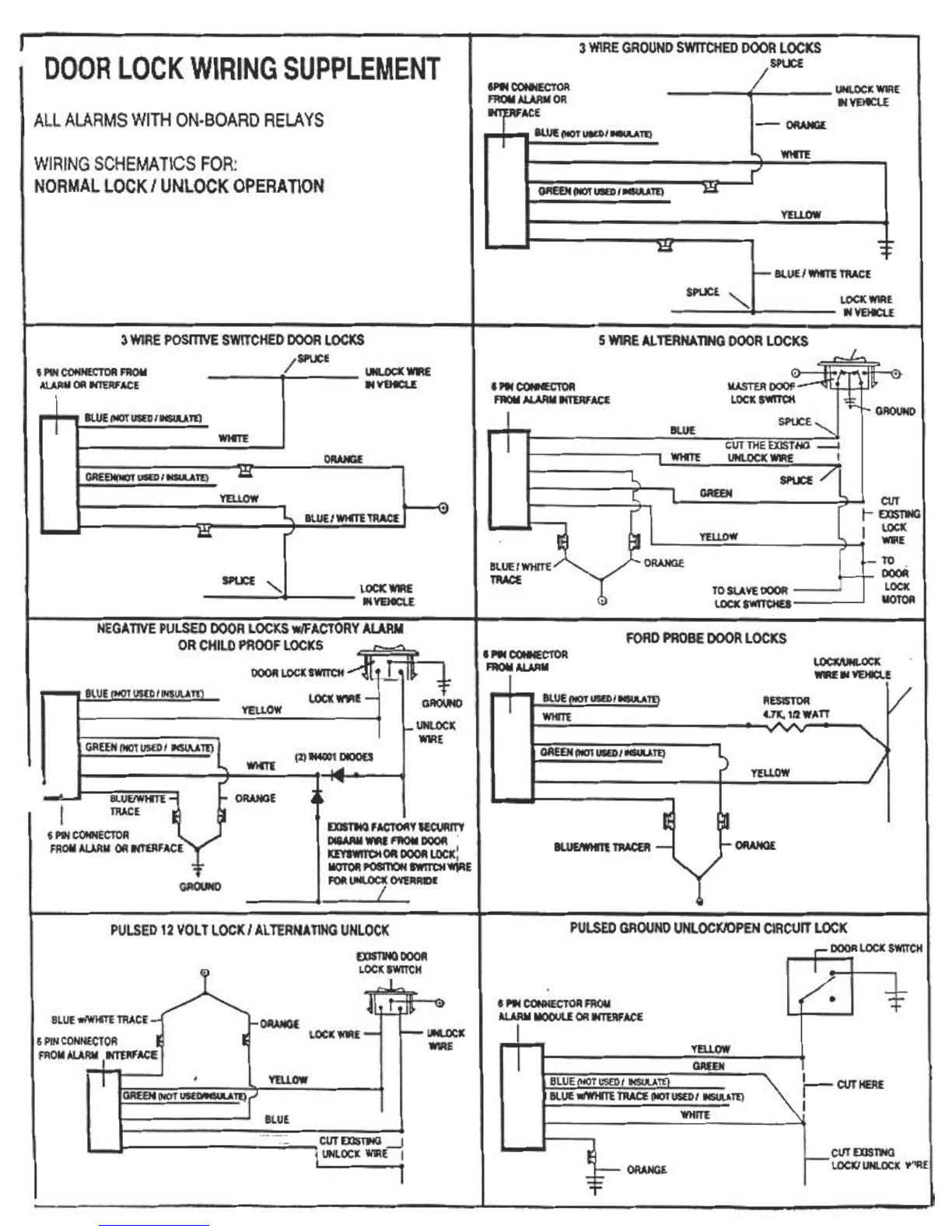
E.Onceyou haveidentifiedwhichtypeof Jocksyou
have, you must mark what the wire did (lock,
unlock,12V,Ground,etc.).
F. Withall the abovecompletedreferto theWiring
Diagramthatisapplicabletoyourdoorlockswitch
andwiretheunitasshown.
G. When the k>ckwiring is completed,test system
usingthelock-unlockremotecontroltransmitter.If
thedoorlockingandunlockingactionis reversed
fromtheotheralannfunctions,youmustreverse
the lock-unlocksplicedwires(example:doorun-
locks when you use the transmitterto ann the
alannandlockwhenyoudisarmthealarm).
B. 3-Wire Negative Switched Lock (Some Ford &
foreignvehicles).
C. 4 or 5-WirePolarityReversalLock(MostFord&
Chrysler&someGM).
D.Theuseof a voltagetest meteror testlightwill be
requiredto determinewhichof the threetypesof
switchesisinyourvehicle.
a. 3-WirePositive Switched Locks: Onewirewill
be 12Vpositiveat alltimes,onewirewill be 12V
positivewhentheswitchisinthe.lock.mode,and
thelastwirewillbe12Vpositivewhentheswitch
is inthe .unlock.mode.
b.3-WireNegativeSwitched Locks: Onewirewill
begroundedatalltimes,onewirewillbeground-
edwhentheswitchisinthe.lock.mode,andthe
lastwirewillbegroundedwhentheswitchisinthe
.unlock.mode.
c. 4 or 5-WirePolarity ReversalLocks: Onewire
willbe12Vpositiveatalltimes,oneortwowires
will be groundedat all times. All the remaining
wireswillbe12Vpositivewhentheswitchisinone
EXCLUSIONS:
CANNOTBE USEDINANYVEHICLEHAVINGTHE
FOLlOWINGTYPESOF POWERDOORLOCKING
SYSTEMS:
A.VACUUMOPERATEDPOWERDOORLOCKS
B. DOOR LOCKINGSYSTEMSREQUIRINGKEY
LOCKINGOFTHEDRIVER'SDOORINORDERTO
REMOTELY LOCKTHEOTHERDOORS.
NQIE: OPTIONAl KIT PDA-1IS AVAILABLEFOR
BOTHTHEABOVEAPPLICATIONS.
INSTRUCTIONS(ALL VEHICLES)
1. Removedriver'sdoorpanelfor access to existing
powerdoorswitchwiring.
2.Mountthemoduleinthekickpanelareaofthedriver's
sideofthevehicle.
3. Routethe wires into the driver's door using the
existingwiringtubeasaccess.
4. Examinetheexistingpowerdoorlockswitchin the
driver'sdoortodeterminewhichwiringmethodmust
beused.Thedoorswitchwillbeoneofthefollowing:
A.3-WirePositiveSwitchedLock(MostGMvehicles)
'verrouUlage' correspondau 12Vpositifetla
massealaposition'deverrouillage'ouI'inverse
surd'autresvoitures).
E. Apres avoir Mjentif~le type de verrouillagede
votrevehicule,utautmarquerlafonctiondechaque
fil (verrouillage,deverrouillage,12V, mise a la
masse).
F.Unefoistoutescesoperationsterrninees,reportez-
vous au schemade cablagecorrespondantau
verrouillagede votre porte et cablez l'appareU
commeindique.
G. Le cablage du verrouillagetermine, testez le
systemeenutilisantlatelecommandeadistance
verrouillage-deverrouillage. Si I'action de
verrouillageet de deverrouillagesont inversees
parrapportauxautresfonctionsdeI'alarrne,iltaut
inverser les fils coupes de verrouillage-
deverrouillage(exemple:laportese deverrouille
lorsquevousutilisezI'emetteurpourarrnerI'alarrne
et severrouillelorsquevousdesarrnezI'alarme).
B.Verrouillagedeportea3filsparimpulsionnegative
(certainsmodelesFordetvehiculesetrangers}.
C.Verouillagedeportea4ou5filsapoiariteinversee
(laplupartdesmodelesFordetChrysleretcertains
modelesGM.
D. II est necessaired'utiliser un voltmetreou un
voyantd'essaipoursavoirqueltyped'interrupteur,
parmiles3types,estutilisesurvo!revehicule.
a}Verrouillage depones a3fils parimpulsion
positive: Unfilestconstammentau12Vpositif,
unfirestau12VpositiflorsqueI'interrupteurest
enposition"verrouillage'('lock'}, et le demier
filestau12VpositiflorsqueI'interrupteuresten
mode'deverrouillage'('unlock'}.
b}Verrouillage deprotes a3fils par impulsion
negatuve: Un fil est a la masseen perma-
nence,unfilestalamasselorsqueI'interrupteur
estenposition"verrouillage'etledernierfilest
alamasseIorsqueI'interrupteurestenposition
'deverrouillage'.
c} Verrouillage de pone a4 ou 5 fils a polarite
Inversee:Unfilest12Vpositifenpermanence,
unoudeuxfilsson!alamasseenpermanence.
Touslesfilsrestantsson!en12Vpositiflorsque
I'interrupteurestdansI'unedesdeuxposition
(verrouillageoudeverrouillage}etreviennenta
lamasseIorsqu'onmetI'interrupteursurI'autre
position (sur certains voitures, la position
EXCLUSIONS:
NE PEUT PASS'UTIUSERSUR LES VEHICULES
EoulPEs DE PORTES A VERROUILLAGE
ELECTRIOUEDETYPESUIVANT:
A. LESPORTESA VERROUILLAGEELECTRIOUE
FONCTIONNANTPARLEVIDE.
B.LESSYSTEMESDEVERROUILLAGEDEPORTES
NEcESSITANTLE BLOCAGEPAR CLE DE LA
PORTEDU CONDUCTEURAFIN DE POUVOIR
VERROUILLER A DISTANCE LES AUTRES
PORTES.
~: LEKITPDA-1ENOPTIONESTDISPONIBLE
POURLESDEUXCASDEcRITSCI-DESSUS.
NOTICE DE MONTAGE (POUR TOUS LES
VEHICULES)
1.Demontezlepanneaudelaporteduconducteurpour
accederau cAblageexistant de rinterrupteurde
verouillageelectriquedespones.
2.Montezlemoduledanslapanieinferieuredupanneau
duvehiculecOteconducteur.
3. Acheminezles fils dansla pone du conducteuren
passantparletubedecAblageexistant.
4. Examinez rinterrupteur existant de verrouillage
electriquede pones sur Ia.pone cOteconducteur
pourdeterminerla rnethodedecAblagea adopter.
L'interrupteurde pone est run des interrupteurs
suivants:
A. Verrouillagede pones a 3 fils par impulsion
positive(laplupartdesvehiculesGM).
128-4177A
B. 3-Cerradurade conmutacionnegativa (algunos
vehlculosFordyextranjeros).
C.405-Cerraduraconinversiondepolaridad(mayorla
devehlculosFordy Chryslery algunosGM).
D. Senecesitaun medidordevoltajeo de unaluzde
pruebaparadelerrninarcuAIdeeslosIrestiposde
inlerruploressehallaensuvehlculo.
a)Cerradurasdeconmutaci6npositivade3alambres:
UnodeIosalambreslendrA12voltiosdecorrienle
positivalodoel tiempo,olrolendrA12voltiosde
corrienlepositiva cuandoel inlerruplorsehalla
enel modode"cerrar"(lock)y el ultimoalambre
lendrA12voltiosdecorrienlepositivacuandoel
inlerruplorse hallaen el modo"abrircerradura"
(unlock).
b) Cerraduras de conmutaci6n negativa de 3
alambres:Unalambraestaraconectadoatierra
lodoeltiempo,olroconectarBal ierracuandoel
inlerruplorsehallaenelmodode"cerrar"(lock)
y el ultimoalambreconectarAatierracuandoel
inlerruplorestaenelmodo"abrir"(unlock).
c) Cerradurasde inversi6nde polaridadde 4 6 5
alambres: Un alambre tendrB 12 voltios de
corrienle positivatodo el tiempo y uno o dos
alambresestarBnconectadosa tierra lodo el
tiempo.TodosIosalambresrestantestendran
12 voltios de corrientepositiva cuando el
interruptorsehallaenunadelasdosposiciones
(cerraroabrir)einvertiransupolaridadatierra
cuandosemuevaelinterruptoralaotraposici6n
(en algunos vehlculos, tendran 12 voltios
positivos en la posici6n "cerrar" y estaran
conectadosa tierraen la posici6n"abrir"o 10
inversoenotrosvehlculos).
E. Unavel identificadoel tipo de cerradurade su
autom6vil,debemarcarlafunci6ndeIosalambres
(cerrar,abrir,12 voltios,tierra,etc.).
F. Una vel completado 10anterior, refierase al
diagramadecableadocorrespondientealtipode
cerraduradesupuertay conectela unidaddela
maneraindicada.
G. Unavel terrninadoel cableadode la cerradura,
prubeelsistemausandoeltransmisordecontrol
remotoparacerrary abrir. Si laacci6ndecerrar
y abrirdelacerradurase inviertedesdelasotras
funcionesde la alarrna,usted debe invertirk>s
cablesseccionadosparacerraryabrir(ejemplo:la
puertaseabrealusareltransrnisorconelprop6sito
de activarla alarrnay se cierraal desactivarla
alarrna).
EXCLUSIONES:
NOPUEDEUSARSEENNINGUNVEHlcULOCON
LOS SI\3UIENTES TIPOS DE SISTEMAS DE
CERRADURAPARAPUERTASDEPOTENCIA:
A. CERRADURASDE PUERTA DE POTENCIA
OPERADASALVAclo.
B. SISTEMASDE CERRADURASDE PUERTAS
QUEREQUIERENCIERRECON LLAVEDE LA
PUERTADELCONDUCTORAFINDEASEGURAR
ACONTROLREMOTOLASDEMAsPUERTAS.
~ KIT OPCIONALPDA-1 ESTADISPONIBLE
PARALOSOOSCASOSANTERIORES.
INSTRUCCIONES(PARATODOSLOSVEHICULOS)
1.RetireelpaneldelapuertadelconductorparalIegar
alcableadodelinterruptordelapuertadepotencia.
2.Instaleelm6duloenelareaparalospiesenellado
delconductordelvehlculo.
3. Extiendak>scableshaciala puertadelconductor
empleandocorno medio de acceso el tubo de
cableadoexistente.
4.Examineelinterruptordecerraduradepotenciade
lapuertadellado delconductorafindedeterminar
quemelododecableadodebeusarse.Elinlerruptor
dela puertaseraunode Iossiguientes:
A. 3-Cerraduradeconmutaci6npositiva(mayorla
devehlculosGM).
BLUE,YELLOW,WHITE,GREEN,ORANGE,BLUE/WHITEc
SEEPOWERDOORLOCKSUPPLEMENTENCLOSED.
BLEU,JAUNE,BLANC,VERT,ORANGE,BLEU/BLANC.SE
REPORTERAUSUPPLEMENTPORTESAVERROUILLAGE
ELECTRIQUECI-JOINT.
VEAELSUPLEMENTOADJUNTODECERRADURASDE
POTENCIAPARAAZUL,AMARILLO,BLANCO,VERDE,
ANARANJADOYAZUL/BLANCO.
6-WIRECONNECTOR
CONNECTEURA6ALS
CONECTORDE6AlAMBRES
11011
~
~~ 15A FUSE (2)
FUSIBLE DE 15A (2)
FUSIBLE DE 15A (2)
-
~-.:~
CONNECTEURA4FILS
CONECTORDE4ALAMBRES
d
2WIRECONNECTOR,RED&BLACKWIRES.
PLUG INTOMAnNG 2 WIRECONNECTOR
FROMALARM.
CONNECTEURA 2 FILS, FILS ROUGEET
NOIR.BRANCHEZsURLECONNECTEURA
DEUXFILSCORREsPONDANTVENANTDE
L'ALARME.
CONECTOR DE DOS CABLES, CABLES
ROJO y NEGRO. CONECTE EN EL
CONECTOR DE EMPALME DE 2 CABLES
DELA ALARMA.
REDCONNECTTOREDWIREFROMALARMHARNESS.
LEROUGESEBRANCHESURLEAL ROUGEDUHARNAISDEL'ALARME.
ROJOSECONECTAALCABLEROJODELCABLEADOPREFORMADODELA
ALARMA.
BLACKTOCHASSISGROUND -
NOIRREUEALAMASSEDUCHAsSIS
NEGROSECONECTAATlERRAENEl CHASIS
128-4177A
ALLALARMSWITHON-BOARDRELAVS
WIRING SCHEMATICS FOR:
NORMAL LOCKI UNLOCK OPERATION
---L...
.PIf CONNECTOR
FROM ALARMI(TERFACE LOCK SWITCH GROUNO
BLUE
-I
WJfTE UNLOCK WIRE I
SPLx:E /1
GREEN ~ CIJT
r EXISTING
I LOCK
, WIRE
TO .
DOOR
LOCK
MOTOR
~
w~YEllOW
nIACE TOSLAVEDOOR
LOCKSWJTCHES
NEGATIVEPULSEDDOORLOCKSw/FACTORYALARM
ORCHILDPROOFLOCKS r---'"\
DOORLOCKSWITCH~ LI1]r
T
GROUND
UNLOCK
WVIE
~ BLUE(NOTUSEDIINSUlAm LOCKWVIE
YEllOW
I GREEN (NOT USED I INSUlATElI (2)W4OO1DIOOES
~-
WHITE
~ BLUE/WHITE
TRACE
6 PINCONNECTOR
FROMALARM OR MERFACE
ORANGE
-'
~ FACTORYSECURrry
~ WIREFROMDOOR ,
KEY1WITCHOR DOORLOCK:
MOTORPOSIT1ONSWTTCHWIRE
FOR\JjLOCK OVERRIDE
/
T
GROUND
PULSED GROUND UNLOCK/OPEN CIRCUrr LOCK
DOORLOCKSWITCH
Ie,.-
PULSED12 VOLT LOCKI ALTERNATINGUNLOCK
EXIST1NGDOOR
LOCKSWITCH
~s PW CONNECTOR FROM
AlARM MODULE OR INTERFACE
BLUEw/WHITETRACE
i6 PINCONNECTOR ORANGE LOCK WIRE UNLOCK
WIRE ~YELLOW
-YELLOW j- CUT HERE
I BLU!~rrc TRACE (IK)T USEDI ~TE)
BLUE WHfTE
CUT EXISTWG ~
I UNLOCK WIRE I CUTEXISTING
LOCKIUNLOCKY:'RE
ORANGE
T

This manual suits for next models

1

Other Audiovox Recording Equipment manuals

Audiovox AS-9159 User manual

Audiovox

Audiovox AS-9159 User manual

Audiovox ST195 User manual

Audiovox

Audiovox ST195 User manual

Popular Recording Equipment manuals by other brands

Tigertronics SignaLink SL-1+ Installation & operation

Tigertronics

Tigertronics SignaLink SL-1+ Installation & operation

XTA DP226 How-to

XTA

XTA DP226 How-to

Iso-Max CI-RJ2R-T user guide

Iso-Max

Iso-Max CI-RJ2R-T user guide

Mitsubishi Electric DX-NT400E Installation and operation manual

Mitsubishi Electric

Mitsubishi Electric DX-NT400E Installation and operation manual

ABB MRP31.0 Technical description

ABB

ABB MRP31.0 Technical description

Siemens SITOP PSU6200 Applications manual

Siemens

Siemens SITOP PSU6200 Applications manual

Triax HDA 1EQ operating manual

Triax

Triax HDA 1EQ operating manual

Nonlinearcircuits Numberwang Build guide & BOM

Nonlinearcircuits

Nonlinearcircuits Numberwang Build guide & BOM

Yamaha MW8cx owner's manual

Yamaha

Yamaha MW8cx owner's manual

ProSoft Technology MVI56E-MCMXT installation manual

ProSoft Technology

ProSoft Technology MVI56E-MCMXT installation manual

Dahua Technology BC581E82 Quick install guide

Dahua Technology

Dahua Technology BC581E82 Quick install guide

NEAL 9102 operating instructions

NEAL

NEAL 9102 operating instructions

AMX AXB-TPI/3 instruction manual

AMX

AMX AXB-TPI/3 instruction manual

ZABKZ PA2184B owner's manual

ZABKZ

ZABKZ PA2184B owner's manual

Mascom MC513000 operating manual

Mascom

Mascom MC513000 operating manual

Atonal circuits A02 quick start guide

Atonal circuits

Atonal circuits A02 quick start guide

ETS PMI-4 instructions

ETS

ETS PMI-4 instructions

Pioneer PDR-509 Service manual

Pioneer

Pioneer PDR-509 Service manual

manuals.online logo
manuals.online logoBrands
  • About & Mission
  • Contact us
  • Privacy Policy
  • Terms and Conditions

Copyright 2025 Manuals.Online. All Rights Reserved.