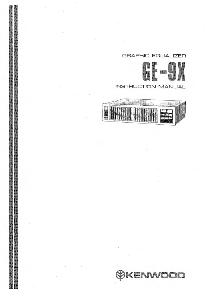
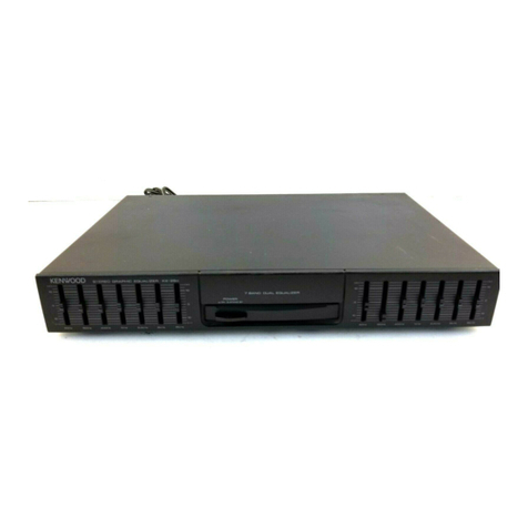
Kenwood GE-600 User manual

STEREO
GRAPHIC
EQUALIZER
KENWOOD
G
E
600
KENWOOD
CORPORATION
INSTRUCTION
MANUAL
@©PRINTED
IN
JAPAN
B50-6511-O0(E,
U,
M,
UE,
A)(T)
87/21110987654321
862i
For
your
records
Record
the
serial
number,
found
on
the
back
of
the
unit,
in
the
spaces
designated
on
the
warranty
card,
and
in
the
space
provided
below.
Refer
to
the
model
and
serial
numbers
whenever
you
call
upon
your
dealer
for
information
or
service
on
this
product.
Model!
Serial
number.
Unpacking
Unpack
the
unit
carefully
and
make
sure
that
all
accessories
and
cables
are
put
aside
so
they
will
not
be
lost.
Examine
the
unit
for
any
possibility
of
shipping
damage.
If
your
unit
is
damaged
or
fails
to
operate,
notify
your
dealer
immediately.
lf
your
unit
was
shipped
to
you
directly,
notify
the
shipping
company
without
delay.
Only
the
consignee
(the
person
or
company
receiving
the
unit)
can
file
a
claim
against
the
carrier
for
shipping
damage.
We
recommend
that
you
retain
the
original
carton
and
pack-
ing
materials
for
use
should
you
transport
or
ship
the
unit
in
the
future.
WARNING:
TO
PREVENT
FIRE
OR
ELECTRIC
SHOCK
DO
NOT
EXPOSE
THIS
AP-
PLIANCE
TO
RAIN
OR
MOISTURE.
Rear
panel
safety
precautions
CAUTION
CAUTION:
TO
REDUCE
THE
RISK
OF
ELECTRIC
SHOCK,
DO
NOT
REMOVE
COVER
SRK
OF
LER
TRIGR
BOCK
(OR
BACK).
NO
USER-SERVICEABLE
PARTS
INSIDE.
REFER
SERVICING
TO
RO
NOT
OREN
QUALIFIED
SERVICE
PERSONNEL.
The
lightning
flash
with
arrowhead
symbol,
within
an
equilateral
triangle,
is
intended
to
alert
the
user
to
the
presence
of
uninsulated
‘dangerous
voltage’’
within
the
product's
enclosure;
that
may
be
of
sufficient
magnitude
to
constitute
a
risk
of
electric
shock
to
persons.
The
exclamation
point
within
an
equilateral
triangle
is
intended
to
alert
the
user
to
the
presence
of
important
operating
and
maintenance
(servicing)
instructions
in
the
literature
accompanying
the
appliance.

Important!
Europe,
Australia
and
U.K.
Units
shipped
to
Europe
are
designed
for
operation
on
220
volts
AC.
Units
shipped
to
Australia
and
U.K.
are
designed
for
operation
on
240
volts
AC.These
units
are
not
equipped
with
an
AC
voltage
selector
switch
and
the
discussion
of
such
a
switch
that
follows
should
be
disregarded.
All
other
countries
Units
shipped
to
countries
other
than
the
above
coun-
tries
are
equipped
with
an
AC
voltage
selector
switch
on
the
rear
panel.
Refer
to
the
following
paragraph
for
the
proper
setting
of
this
switch.
AC
voltage
selection
This
unit
operates
on
110-120
volts
or
220-240
volts
AC.
The
AC
voltage
selector
switch
on
the
rear
panel
is
set
to
the
voltage
that
prevails
in
the
area
to
which
the
unit
is
ship-
ped.
Before
connecting
the
power
cord
to
your
AC
outlet,
make
sure
that
the
setting
position
of
this
switch
matches
your
line
voltage.
If
not,
it
must
be
set
to
your
voltage
in
accordance
with
the
following
direction.
Note:
Our
warranty
does
not
cover
damage
caused
by
excessive
line
voltage
due
to
improper
setting
of
the
AC
voltage
selector
switch.
2
GE-600
AC
110-120V~
<a>
AC
220-240V~
AC
110-120V~
ab
AC
220-240V~
This
shows
switch
lever
is
locked
in
220-240V~
position.
This
shows
switch
lever
is
locked
in
110-120V~
position.
Move
switch
lever
to
match
your
line
voltage
with
a
small
screw
driver
or
other
pointed
tool.
AC
voltage
selector
switch
For
United
Kingdom
The
mains
plug
must
be
removed
from
the
wall
socket
prior
to
any
internal
examination.
Important
The
wires
in
this
mains
lead
are
coloured
in
accordance
with
the
following
code:
BlU
Cee
sin.
gro
alate
cent
vnteoteenpted
ode
Neutral
BOW
ng.c
oes
enevieneeroutect
de
eek
Live
The
wires
in
this
mains
lead
must
be
connected
to
the
terminals
in
the
plug
as
follows:
Wire
colour
Plug
terminal
marking
Blu
Gas
2
Asiiesed
cd
Aes
latieeesins
N
or
Black
BIOWM
tides
aroevdiadecathaeasenae:
L
or
Red
|
CS
E
Brown
to
als
See
Live
|
Blue
to
_
L
Neutral
|
Plug
——|—
\
a
Notes:
1)
1f
a
13-amp
plug
is
used,
this
must
be
fitted
with
a
5-amp
fuse.
2)
If
a
3-pin
plug
with
earthing
contact
is
used,
no
wire
must
be
connected
to
the
E
terminal.

2
SERS
oomeg
Controls
and
indicators
o
8
8
68
KENWOOD
|
sterco
crapuic
EQUALIZER
GE-600
r
LEFT.
Ef
RANGE
+2
foe
De
1208
EQUALIZER
REC
TUT
jum]
MLA]
F
iLO
ATI
[amt]
Il
0
ATTN
[em
601
=
Fa
@
POWER
switch
Press
this
switch
to
turn
on
the
power.
To
turn
off
the
power,
press
the
switch
again.
@
Level
control
(RIGHT/LEFT
channel)
Adjust
these
controls
up
and
down
to
equalize
the
sound
by
+12
dB
or
+6
GB
with
the
center
frequency
indicated.
The
right
and
left
channels
can
be
equalized
separately.
Level
control
indicators
light
when
the
EQUALIZER
switch
is
pressed.
®
INPUT
switches
Use
this
switch
to
select
the
program
source
to
be
equalized.
LINE:
To
equalize
the
program
source
connected
to
the
LINE
IN
jacks.
TAPE:
To
equalize
the
program
source
connected
to
the
TAPE
PLAY
jacks.
@
EQUALIZER
switches
EFFECT:
Press
this
switch
to
on
the
frequency
characteristic
will
be
modified
by
passing
through
the
graphic
equalizer.
REC:
Press
this
switch
to
on
signals
will
allow
equalized
to
be
recorded
on
tape.
lf
you
want
to
monitor
the
equalized
sounds,
press
the
EQUALIZER
EFFECT
switch
to
on.
4)
©
Equalizer
recording
indicator
(REC)
Lights
when
the
equalizer
recording
switch
(EQUALIZER
REC)
is
set
to
on.
@
Equalizer
range
selector
switch
(EQ
RANGE)
Use
to
choose
the
maximum
equalization
range
to
+12
dBor
+6
cB.
@
Equalizer
indicator
(EFFECT)
Lights
when
the
EQUALIZER
EFFECT
switch
is
set
to
on.
@
TAPE
INPUT
indicator
(TAPE)
Lights
when
the
TAPE
INPUT
switch
is
set
to
on.
©
LINE
INPUT
indicator
(LINE)
Lights
when
the
LINE
INPUT
switch
is
set
to
on.
GE-600
3

System
connections
Speaker
system
Pre-main
amplifier
Turntable
GE-600
rear
panel
ft
REC
PLAY
ouT
IN
N
out
6
»
}
UNSWITCHED
o
TOTAL
300W
MAX.
Fy
JE
To
AC
outlet
AC
outlet
(UNSWITCHED)
(Except
some
areas)
This
outlet
provides
power
when
the
unit
is
plugged
into
an
active
AC
wall
outlet,
regardless
of
the
setting
of
the
POWER
switch.
Its
total
maximum
|
capacity
is
300
watts.
Line
IN-UNE
CT
a>
pihy
Tape
deck
g
)
Connections
and
precautions
1.
Before
connecting
or
disconnecting
any
cord,
be
3.
Do
not
bind
the
input/output
cords
with
the
power
sure
to
turn
off
the
power
switches
of
the
unit
and
cord
and
speaker
cord.
Do
not
extend
the
input/out-
pre-main
amplifier.
put
cords
unnecessarily
to
avoid
the
possibility
of
2.
Each
RCA
pin-plug
cord
must
be
connected
securely
noise
or
deterioration
of
tone
quality.
to
the
corresponding
terminals
([L]
to
1]
and
[R]
to
[R]
).
4
GE-600

Ak
ant
Operating
instructions
Mi
To
equalize
the
program
source
connected
to
the
amplifier
1.
Set
the
POWER
switch
to
ON.
The
indicator
lights.
2.
Set
the
INPUT
switch
to
LINE.
3.
Set
the
EQUALIZER
EFFECT
switch
to
ON.
The
in-
dicator
lights.
KENWOOD
srento
cnarmc
eauauzen
ct-600
4.
Play
the
program
source
connected
to
the
amplifier.
5.
Adjust
the
level
controls
(RIGHT/LEFT
channel)
to
compensate
the
sound
quality.
LEFT
a
|
°
\—
eno
He
sso
400He
re
Rie
POWER
‘
i
To
equalize
tape
sound
1.
Set
the
POWER
switch
to
ON.
The
indicator
lights.
2.
Set
the
INPUT
switch
to
TAPE.
3.
Set
the
EQUALIZER
EFFECT
switch
to
ON.
The
in-
dicator
lights.
KENWOCD
_
srenco
crapnic
eauauzen
cesoo
4.
Set
the
tape
deck
to
the
playback
mode.
5.
Adjust
the
level
controls
(RIGHT/LEFT
channel)
to
compensate
the
sound
quality.
M@To
record
amplifier’s
program
source
after
equalization
.
Set
the
POWER
switch
to
ON.
2.
Press
the
INPUT
LINE
switch
to
on.
The
LINE
in-
dicator
will
light.
3.
Set
the
EQUALIZER
REC
switch
to
on.
The
equalizer
recording
effect
indicator
(REC)
will
light.
4,
Play
the
program
source
connected
to
the
amplifier.
5.
Use
the
equalizer
rang
selector
(EQ
RANGE)
to
select
the
appropriate
maximum
equalization
range.
=
KENWOOD
sreaco
casmuc
ravauzin
cé-600
6.
Adjust
the
level
controls
(Right/Left
channel)
to
com-
pensate
the
sound
quality.
The
equalized
sound
can
be
checked
by
the
EQUALIZER
EFFECT
switch
to
on
or
off.
7.
Set
the
tape
deck
to
the
rec
pause
mode
and
adjust
the
recording
level.
8.
Set
the
tape
deck
to
the
recording
mode.
Equalized
sound
can
be
recorded.
LEFT.
Ge-600
5

Sound
equalization
@
Super
bass
range
(60
Hz)
Approximate
frequency
ranges
for
musical
instruments
When
these
controls
are
moved
up,
the
bass
instru-
and
voice
ment
(double
bass,
bass
drums
or
pipe
organ,
etc.)
sound
is
increased.
When
the
super
bass
sound
is
boomy,
move
these
controls
down.
PIPE
ORGAN
®
Bass
range
(150
Hz)
Usually,
the
resonance
frequency
of
the
listening
room
is
in
this
range.
To
eliminate
bass
resonance,
move
these
controls
down.
CONTRA
BASSOON
|
ee!
CLARINET
®
Mid-bass
range
(400
Hz)
This
range
is
the
basis
of
music.
Whether
the
sound
is
rich
or
not,
depends
on
this
range.
When
the
playback
sound
is
not
so
good,
adjust
these
con-
aTerere)
Re)
trols.
®
Mid
range
(1
kHz,
2.4
kHz)
When
these
controls
are
moved
up
or
down,
the
bariton
or
soprano
voice
is
emphasised/de-empha-
sised.
This
range
is
related
to
the
‘‘presence’’
of
the
music.
@
High
range
(5
kHz)
This
frequency
range
is
related
to
the
hardness
of
———
the
sound.
When
this
control
is
moved
up,
strings
or
brass,
such
as
flute
or
piccolo,
is
emphansed.
When
MATE
VOICE
the
control
is
moved
down,
the
sound
will
be
more
FEMALE
VOICE
5
ree
soothing.
60
Hz
150Hz
400Hz
1kHz
2.4kHz
5kHz
15
kHz
®
Super
high
range
(15
kHz)
This
frequency
range
is
related
to
the
details
of
the
music.
When
these
controls
are
moved
up,
super
high
frequency
instruments,
such
as
triangle
or
cym-
bal,
are
emphasized,
resulting
in
wide
sound
and
echoes.
§
GE-600

SRS
pemagengos4
Safety
precautions
Cleaning
Do
not
use
volatile
solvents
such
as
alcohol,
paint
thinner,
gasoline,
benzine,
etc.
to
clean
the
cabinet.
Use
a
silicone
cloth
or
a
clean
dry
cloth.
Power
cord
Always
insert
or
remove
the
power
plug
from
the
AC
outlet
by
grasping
the
plug
body.
Never
pull
or
stretch
the
cord.
Take
care
that
the
cord
is
not
subject
to
trafic
or
bent
sharply
around
furniture.
Keep
heavy
objects
off
the
cord;
never
route
it
under
rugs,
and
avoid
the
use
of
extra
extension
cord.
At-
tention
to
these
precautions
will
avoid
fire
or
shock
hazards.
In
case
of
difficulty
Service
or
modifications
Do
not
remove
the
cabinet
or
touch
internal
parts.
Refer
all
service
to
qualified
service
personnel.
Unauthorized
modifica-
tions
can
result
in
a
dangerous
shock
hazard
and
can
void
the
warranty.
Installation
precautions
a)
Avoid
locations
subject
to
direct
sunlight.
b)
Avoid
high
or
low
temperature
extremes.
c)
Keep
the
unit
away
from
heat
radiating
sources.
d)
Choose
a
location
that
is
relatively
free
of
vibration
or
excessive
dust.
e)
Make
sure
power
is
off
before
making
any
system
con-
nections.
If
your
unit
should
not
perform
as
expected,
consult
the
table
below
to
see
if
the
problem
can
be
corrected
before
seeking
help
from
your
dealer
or
service
representative.
Symptom
—
Remedy
No
sound
although
AC
is
switched
on.
Indicator
not
illuminated.
Poor
AC
plug
connection.
Check
plug
contact.
No
sound
from
LEFT
and
RIGHT.
1.
Speaker
cables
disconnected.
1.
Check
speaker
connections.
2.
Volume
control
of
amplifier
fully
|
2.
Turn
up
volume
control.
counterclockwise.
Sound
from
one
side
only.
1.
Speaker
cords
disconnected.
1.
Check
speaker
connections.
2.
Input
or
output
cables
disconnected.
|
2.
Check
input
or
output
connections.
3.
Balance
control
of
amplifier
set
to
|
3.
Adjust
balance
controi
of
amplifier.
one
extreme
or
the
others.
Specifications
Equalizer
characteristic
Variable
range
............
0.
e
eect
evens
+12
dB,
+6
dB
(L
&
R
independently
adjustable)
Center
0.00.00
cece
eee
ee
ee ee
60
Hz,
150
Hz,
400
Hz,
1
kHz,
2.4
kHz,
5
kHz,
15
kHz
Frequency
reSpOnse
.........
6.
ce
ccc
cece
eens
10
Hz—40
kHz
+41
dB
Total
harmonic
distortion
.............0...0.0..00.000
cece
Less
than
0.01%
(1
kHz,
all
controis
flat,
output
1
V)
Maximum
output
voltage
.....................0..cce
eee
4V
(1
kHz,
THD
0.01%)
SIN
AUOs
woes
cedcalercns
tals
tbe
detomecd
Reda
e
whe
chomisenes
aude
ave
95
dB
(IHF-A
network)
Input
impedance.........0.00..0
0...
cece
cece
eee
eee
60
k
ohms
Output
impedance
..........0
0...
eect
ee
900
ohms
GI
irs
sod
hts
eb
hi
cia
Getn
san
rasaee
wd
veakeighihen
dteana
cats
O
dB
Power
CONSUMPTION
..............0
0.0.
c
cece
eects
7W
DIMENSIONS
209.
ere
oot
ceed
eiclet
china
ects
W
340
mm
(13-3/8”)
H
84
mm
(3-5/16”)
D
351
mm
(13-13/16”)
Weight.(N@t)!k.
ste
chctatttotl
ander
celina
ea
tional
3.3
kg
(7.3
Ib)
Note:
~
We
follow
a
policy
of
continuous
advancements
in
development.
For
this
reason
specifications
may
be
changed
without
notice.
GE-600
7

KENWOOD
Table of contents
Other Kenwood Recording Equipment manuals

Kenwood
Kenwood KOS-V1000 User manual

Kenwood
Kenwood GE-940 User manual

Kenwood
Kenwood KE-205 User manual

Kenwood
Kenwood KE-294 User manual

Kenwood
Kenwood GE-770 User manual

Kenwood
Kenwood KE-2060 User manual

Kenwood
Kenwood GE-4030 User manual

Kenwood
Kenwood KRK-11 User manual

Kenwood
Kenwood GE-560 User manual

Kenwood
Kenwood DSP-100 User manual

Kenwood
Kenwood IF-10A User manual

Kenwood
Kenwood TK-930 User manual

Kenwood
Kenwood DX-7 User manual

Kenwood
Kenwood KE-894 User manual

Kenwood
Kenwood Nexedge KTI-3 User manual

Kenwood
Kenwood MGR-E8 User manual

Kenwood
Kenwood KRK-18H User manual

Kenwood
Kenwood KGC-4400 User manual

Kenwood
Kenwood GE-940 User manual

Kenwood
Kenwood GE-90 User manual