Audipack Rota-Kit Series User manual
Mounting instructions Rota-Kit series
Copyright Audipack (version 31-03-09)

Installation instruction Rota-Kit series
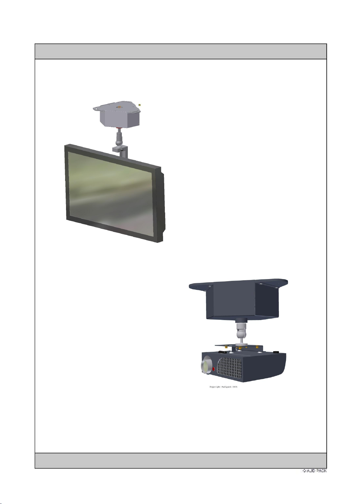
The Rota-Kit is available in various version and are suitable for directing projectors to
projection screens and flat screens towards public. With the 4 free programmable
positions (within 350 degrees), the projector or flat screen can be pointed at any desired
direction.
To mount projectors or flat screen one of the option above mentioned are needed.
Lock the option firmly with the screw and alan key. This prevent unwanted rotation.
Accuracy of positioning:
When the projection screens are beeing installed before the Rota-Kit, the following tolerance
can occur. The tolerance is caused by the resolution of the digital measurement of the Rota-
Kit and the position of the screen. Ones the positions are set, the acuuracy of positioning will
be very high. See below the tolerance measured out in a scheme.
Projection tolerance when pointing on a :
Projection distance
Possible dislocation
at positioning
Tolerance afther
placement
5 meters
10 mm
+/- 1 mm
10 meters
15 mm
+/- 2 mm
15 meters
20 mm
+/- 4 mm
20 meters
25 mm
+/- 8 mm
The tolerance is the difference between the programmed position and the actual reached position compare with the already installed
screen. The shown tolerances are indicated and can only be less then shown.

When the Rota-Kit is beeing installed before the projection screens, the following minimum
tolerance can occur. The tolerance is caused by the resolution of the digital measurement of
the Rota-Kit. The projection screen can be lined out if neccesary with the Rota-Kit.
Ones the positions are set, the accuracy of positioning will be very high. See below the
tolerance measured out in a scheme.
Projection tolerance when repositioning:
Projection distance
Tolerance after
placement
5 meters
+/- 1 mm
10 meters
+/- 2 mm
15 meters
+/- 4mm
20 meters
+/- 8mm
The tolerance is the difference between the programmed position and the actual reached position.
The shown tolerances are indicated and can only be less then shown.
1.
When mounting the Rota-Kit to the ceiling, be aware that the Rota-Kit is installed level.
Be aware of the right direction of the “0” position of the Rota-Kit.
The Rota-Kit has a blind spot of 10 degrees.
Be aware the “0” position is pointed to a non used projection angle.
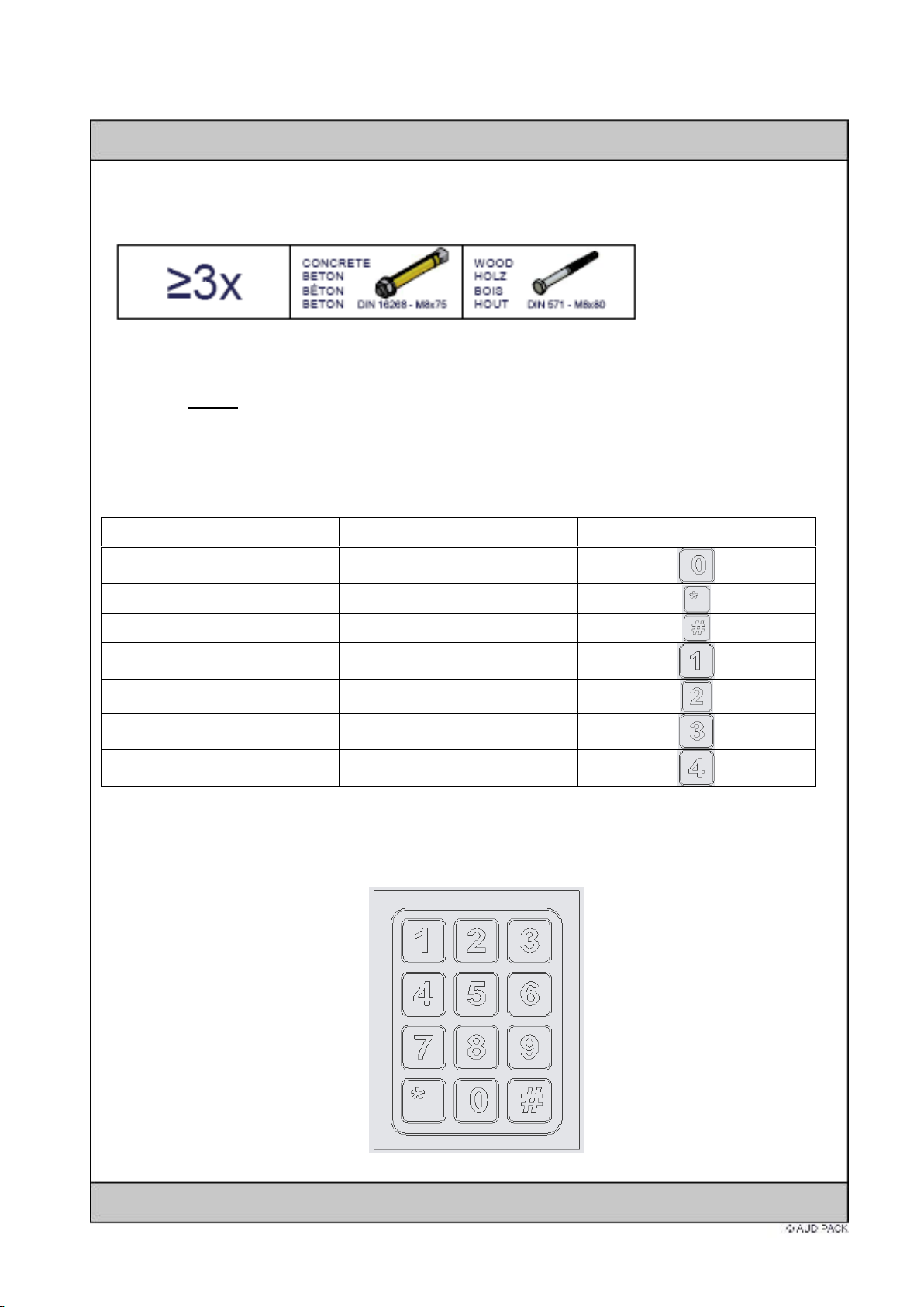
Use minimal 3 bolts or screws to fsten the Rota-Kit.
2.
Screw the keeper on the axis of the Rota-Kit. The type of keeper determines the choice of
load on the Rota-Kit. Screw it on firmly (without tools) and lock the inserts with an
allen-key..
3.
Connect the Rota-Kit according the scheme below:
Function
Wire combinaton
Key board position
Store
C + S
Rotate Left
C + L
Rotate Right
C + R
(Go to) position 1
C + 1
(Go to) position 2
C + 2
(Go to) position 3
C + 3
(Go to) position 4
C + 4
C = common.
Use only potential free contact closures to make the connection.
Max. control cable length aprox. 30 meters, Minimum shielded cable thickness 0.75
mm3.

The wired control can be connected to the green Phoenix connector.
4a.
Mount the projector mount to the projector and mount this assembly to the rota-kit.
Connect the power adapter to the Rota-Kit.
The Rota-Kit will automatically go to it’s “0” position.
Note:
Mount the projector (or other AV equipment) cables in a
way that they are clear from moving parts.
Pre-programming the first position:
Rotate the Rota-Kit for about 10 degrees away from it’s “0” position (homing position).
This can be done by using the wired controll or press on the key-board.
Set the temporarely first position. Press button and within 1 second button .
Aim the projector by loosening the ball joint. When the correct position is found, lock the
ball-joint firmly.
Tip: Always programm the latest position firt. The programm the first position. In this way the
programming will alwys be the most accurate. When using the product, always start form
position 1 to 2 or position 3. When returning form position 4 to 3, stop first at 2, then go to 3.
This will give a higher accuracy of positioning.
Programming the second position:
Rotate the Rota-Kit to the second position. Programm this accurat position.
Confirming and programming the first position:
Return to position 1, bij using the start or fence and reprogramm position .
In this case the accuraty between position and is consistant.
Finally position and can be set.
Note:
Mount the projector (or other AV equipment) cables in a way that they are clear from moving
parts.
4b.
Mount the monitor bracket to the flat screen. Mount this assembly to the rota-kit.
Connect the power adapter to the Rota-Kit.
The Rota-Kit will automatically go to it’s “0” position.
Refer 4a for programming the positions.
Using the Rota-Kit with a remote controll.
When the Rota-Kit is used with the optional 260218 (IR) or 260219 (RF) remote please refer
to the installation manual of the print set.
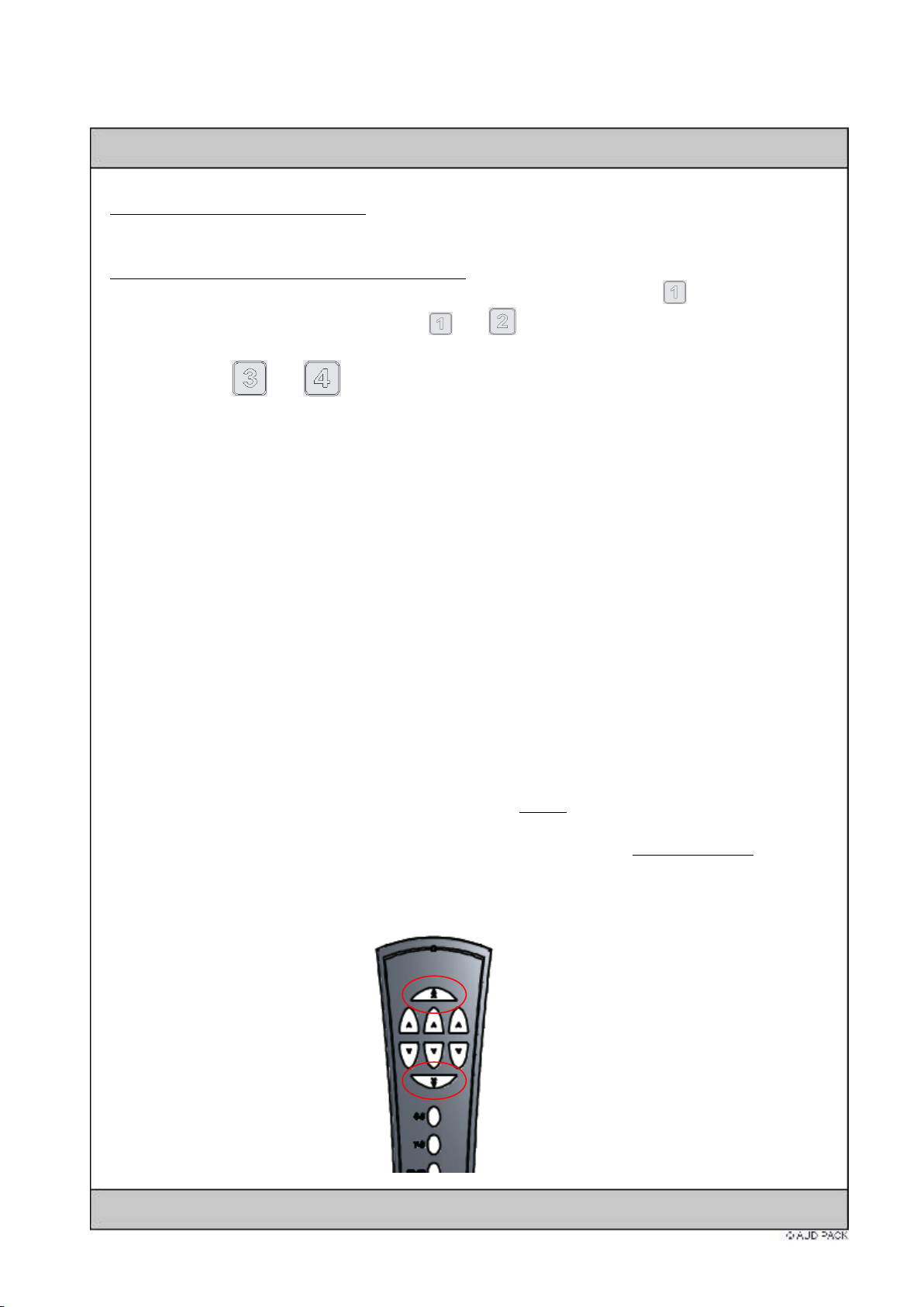
In case 4 positions are controlled by a remote controll, do not press the upper or lower
“general activation” button .
This button with try to activate all 4 positions in 1 time. The Rota-Kit will not respond to that
and stall.
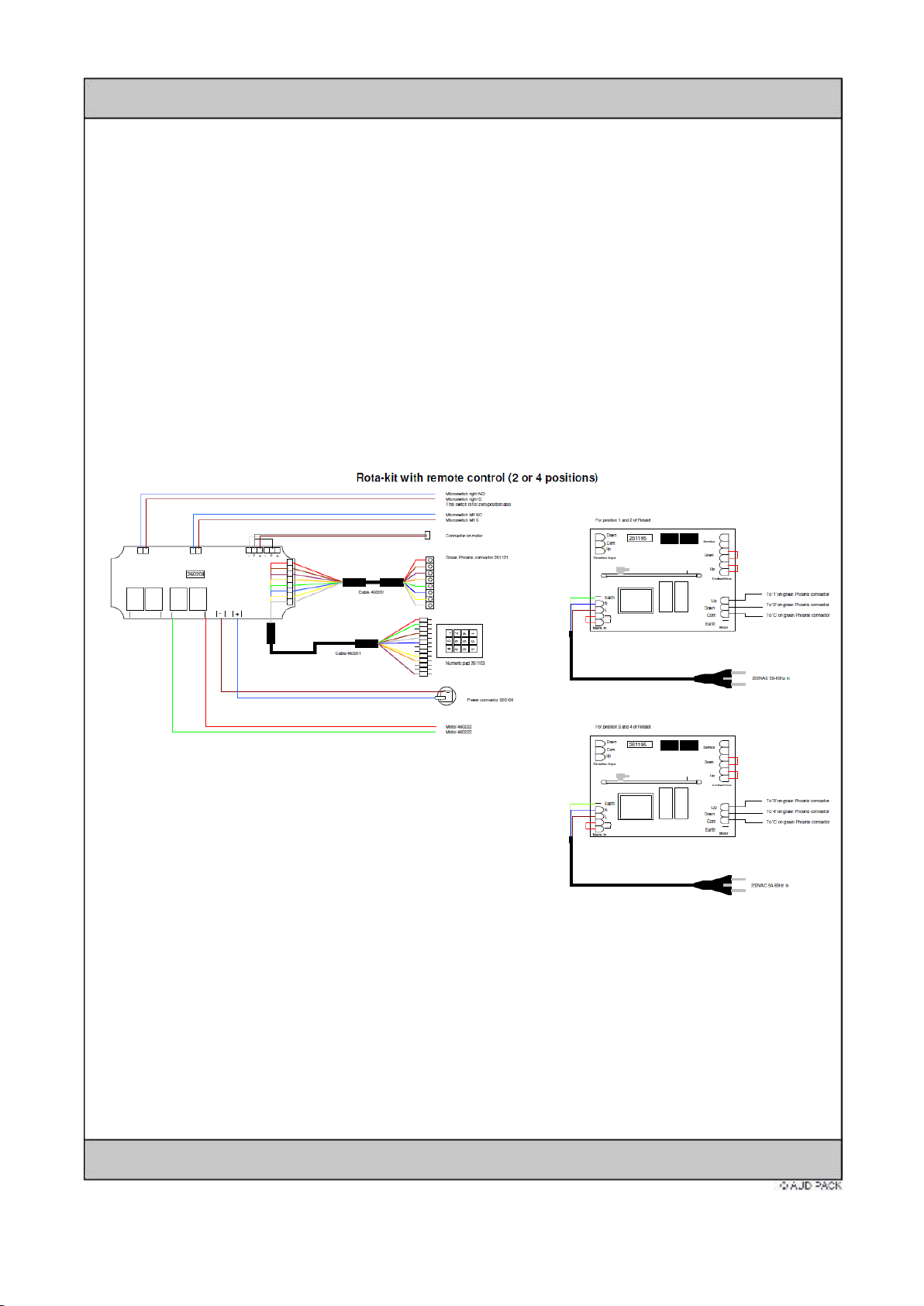
External control of the Rota-Kit.
To controll the Rota-Kit by contact closures or (Audipack) remote controll, please follow the
instructions on the wiring diagram.
Use for each position a separate relay; do not use 1 relay for 2 positions.
Use the below listed Audiapck remote controls for wirless remote.
1 x 260218 Infra red remote for 2 positions
1 x 261227 Infra red remote for 4 positions
1 x 260219 RF remote for 2 positions
1 x 261228 RF remote for 4 positions

General important announcements:
When the power is taken of from the system in static position.
The Rota-Kit will slowly return to it’s “0” position. After “homing” the
programmed position can be activated again. There’s no need for
reprogramming. The Rota-Kit will perform normal speed (inclusive slow-
start and slow-stop).
When the power is taken of from the system in during rotation.
The Rota-Kit will slowly return to it’s “0” position. After “homing” the
programmed position can be activated again. There’s no need for
reprogramming. The repositioning to the first chosen position will
proceed with 30% speed.
A.
When persons are close or nearby the Rota-Kit it is obligated that the operator has constant visual
contact with the lift during it’s travel.
B.
The control panel must be installed or positioned in the way that the operator has constant visual
contact with the Rota-Kit during it’s travel.
C.
The Rota-Kit is not suitable for rotating persons.
D.
It is allowed to mount 1 piece of equipment, keeping the allowed max. load of the Rota-Kit in mind.
E.
When more equipment needs to be installed, the equipment must be assembled in a way that they are
mounted together as 1 piece on the Rota-Kit, keeping the allowed max. load in mind.
F.
When loads are mounted on the Rota-Kit it is important that the point of gravity of the load is centred
under the Rota-Kit.
G.
When the Rota-Kit is faulty during normal use or during testing, it must be put out of function
immediately. The repair must be done by a approved engineers. Clearance of the product after repair
must be given by authorised and trained engineers.
H.
When the product is being changed or mechanically altered, the warranty will end immediately.
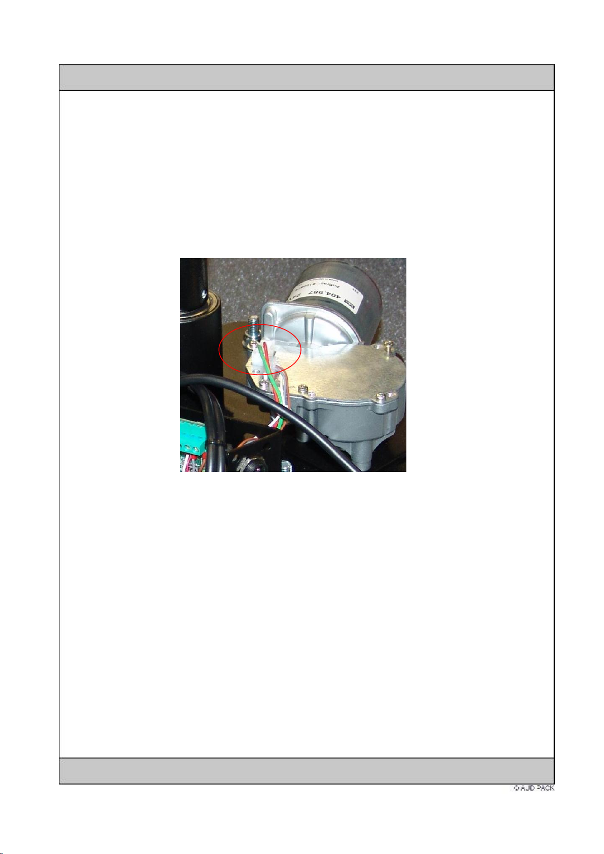
FAQ:
-The Rota-Kit doesn’t memories the programmed positions.
The Rota-Kit is always tested before shipment. It might be possible that the sensor connector
is disconnected or not connected properly. This connector can lose its position during rough
transport or installation.
-Remove the black Rota-Kit cover. Beware of the flat cable!
-Confirm the position of both connectors (motor and sensor).
Clean them if necessary with contact spray.
-Reinstall the cover.
-Test the programming
-The Rota-Kit does not find its “zero point” when the power has been reconnected to the Rota-Kit.
Disconnect the green connector from the Rota-Kit to exclude possible wirering problems
between Rota-Kit and control systems like Crestron / AMX.
Make sure the product is tested as an individual.
Notes:
This manual suits for next models
3
Other Audipack Projector Accessories manuals


Popular Projector Accessories manuals by other brands

Epson
Epson Panamorph ELPALK2 instructions

Crestron
Crestron AM-200 product manual

Grandview
Grandview GPAD42 Series instruction manual

Dream Vision
Dream Vision BEST 3D Passive Assembly and calibration

Kramer
Kramer SMP Series Configuration and card selection guide

Solutions4AV
Solutions4AV FRAME-EVO-E20 manual


