Audipack Rota-Kit PRK-250 User manual
PRK-250/500/750
Projector Rota Kit
Mounting instructions

ii
Safety instructions:
Check the unit for damages caused by transport. In case of damage please
report directly to the transporter and Audipack to provide a quick solution.
Read the manual carefully before installing.
Never install more load on the product than it is allowed.
Unplug before maintenance works.
Please keep this manual for later use.

Index
iii
Table of Contents
1 General features................................................................................... 6
2 Specifications ....................................................................................... 6
2.1 Technical data ................................................................................ 6
2.2 Scope of delivery ............................................................................ 6
2.3 Accessories .................................................................................... 6
3 Tools required for installation ................................................................. 7
4 Mounting the product ............................................................................ 7
4.1 Preparations for ceiling/ floor/ wall mounting ...................................... 7
4.2 Mounting on ceiling ......................................................................... 8
4.2.1 Drilling hole pattern ................................................................... 8
4.3 Mounting to false ceiling................................................................... 8
4.4 Mounting the monitor/ projector ....................................................... 8
4.4.1 Prerequisites of the monitor/ projector (Monitor/ projector info) ...... 8
4.4.2 Adjusting the projector............................................................... 9
5 Required for installation....................................................................... 10
5.1 Homing........................................................................................ 10
5.1.1 The procedure for homing is as follows:...................................... 10
5.1.2 Homing can be activated by:..................................................... 10
6 Connection to mains ........................................................................... 11
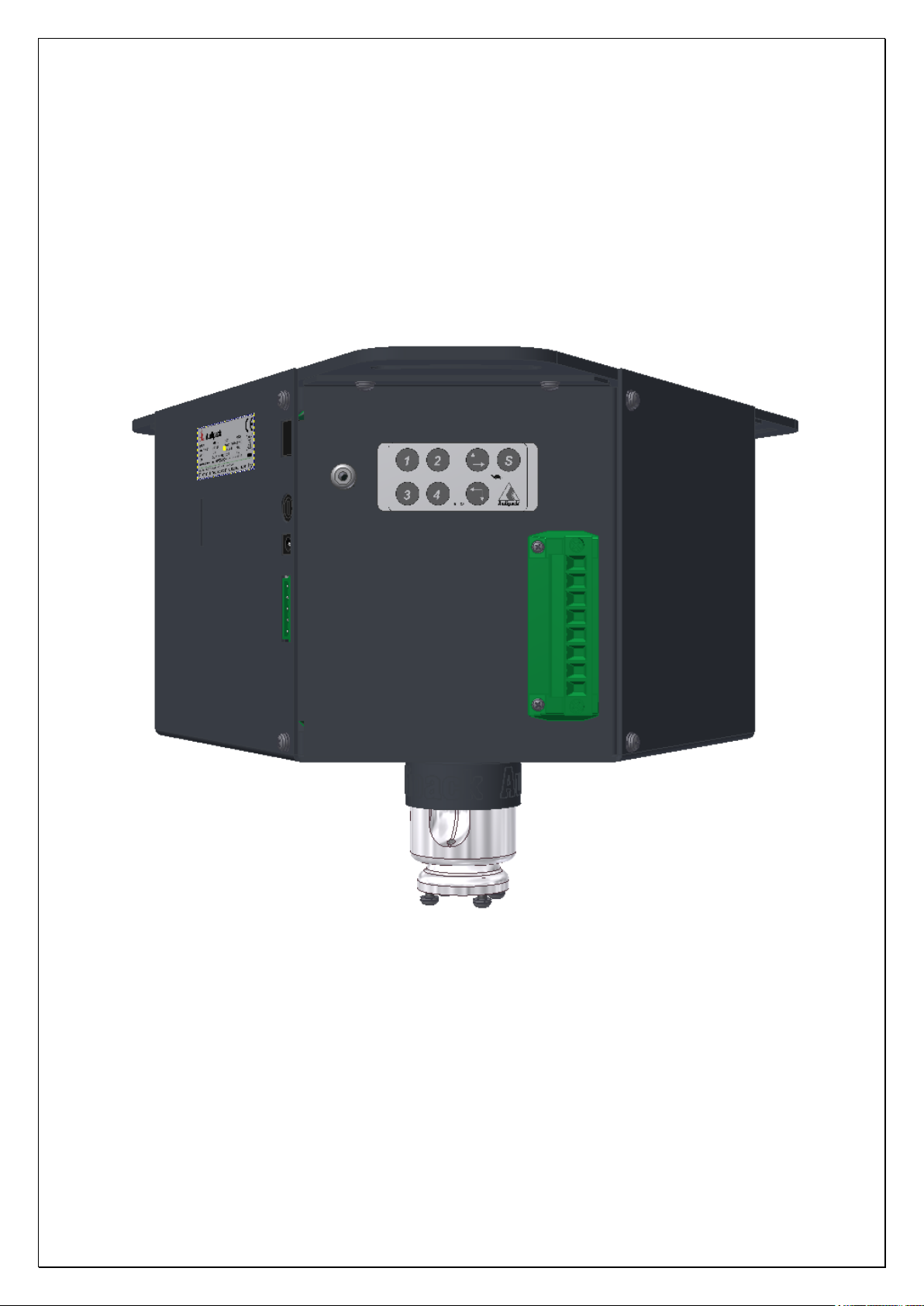
7 Control by inputs 6-pole connector........................................................ 12
7.1 Moving to memory positions ........................................................ 12
7.2 To set a memory position ............................................................ 12
8 Control by inputs 5-pole connector........................................................ 13
8.1 Moving to memory positions ........................................................ 13
9 Control by RS-232 serial communication................................................ 14
9.1 Connection of the RS232 ............................................................. 14
9.2 Moving the lift by serial communication (RS-232) ........................... 14
10 General information ......................................................................... 17
10.1 Definitions .............................................................................. 17
10.2 End switches ........................................................................... 17
10.3 Memory positions and directions................................................ 17

Index
iv
10.4 Memory position control ........................................................... 18
10.5 Error reset .............................................................................. 18
11 Program rotary switch (SW1) ............................................................ 19
11.1 Precautions............................................................................. 19
11.2 Rotary switch positions versus functions ..................................... 19
11.3 Rotary switch positions versus product examples......................... 20
12 Function dipswitches (J14) ................................................................ 20
13 Serial communication RS-232............................................................ 22
13.1 Connections ............................................................................ 22
13.2 Software................................................................................. 24
14 Electric connections.......................................................................... 25
15 Keypad (261288) .......................................................................... 27
16 Instructions RS232........................................................................... 28
16.1 TERMINAL INPUT INSTRUCTIONS .............................................. 28
16.2 INSTRUCTIONS TO CONTROL THE MOTOR.................................. 28
16.3 INSTRUCTIONS TO MOVE THE MOTOR TO A MEMORY POSITION ... 28
16.4 PROGRAM MEMORY POSTIONS.................................................. 28
16.5 FACTORY MODE....................................................................... 28
16.6 MISCELLANIOUS INSTRUCTIONS............................................... 29
16.7 REGISTER R1000 [Device Name]............................................... 29
16.8 REGISTER R1001 [Input Status]................................................ 30
16.9 REGISTER R1002 [Control Function] .......................................... 31
16.10 REGISTER R1003 [UP/DOWN Status] ......................................... 32
16.11 REGISTER R1004 (Motor Status] ............................................... 33
16.12 REGISTER R1005-R1008 [Memory Preset Values) ........................ 34
16.13 REGISTER R1009 [Request Count]............................................. 35
16.14 REGISTER R1010 [Motor Position Count] .................................... 35
16.15 REGISTER R1011 [Motor Error] ................................................. 36
16.16 REGISTER R1012 [Motor Speed Slow mode] ............................... 37
16.17 REGISTER R1013 [Memory Preset Status] .................................. 38
16.18 REGISTER R1014 [Delta pulse].................................................. 39
16.19 REGISTER R1015 [Master/Slave Mode]....................................... 39

Index
v
16.20 REGISTER R1016 [Single/Parallel Mode] ..................................... 40
16.21 REGISTER R1017 (Soft Start Mode] ........................................... 40
16.22 REGISTER R1018 [Pulse/Continue Mode).................................... 41
16.23 REGISTER R1019 [Adjustable Speed Limit Mode]......................... 41
16.24 REGISTER R1021 [limit switch hysteresis homing] ....................... 42
16.25 REGISTER R8888 [Software Version] ......................................... 42
17 Maintenance of the product ............................................................... 43
18 Dimensions and illustrations .............................................................. 44
19 Frequently asked questions ............................................................... 45

Product
6
1General features
Electric rotating system with 4 freely programmable preset positions to rotate a
projector or a flat panel in the horizontal plane. Product height 250/500/750 mm
2Specifications
2.1 Technical data
Power supply 24 Volt, 1.88 A
4 programmable positions
Maximum rotation 350 degrees
Controllable by contact closures, RS232 and optional IR/RF remote.
Max. projector load 30 Kg
Built according CE and EMC norms
2.2 Scope of delivery
Product
Manual
Power adapter
Power cable
5-pole connector with jumper
6-pole connector
2.3 Accessories
Remote control for IR-unit incl. AA battery
Mounting help P3660
Adapter RS232 serial communication RJ45 Sub-D9f (Part number 320137)
Cable serial adapter Sub-D9 (male) USB (Part number 320139)

Assembling
7
3Tools required for installation
drill
drill bit
ring spanner
screwdriver
spirit level
ceiling fixing
hex spanner
tape measure
4Mounting the product
4.1 Preparations for ceiling/ floor/ wall mounting
Make sure the mounting surface area is flat. Make sure there is enough clearance
to operate the product. (Keep in mind free space for future maintenance)
Assembling
8
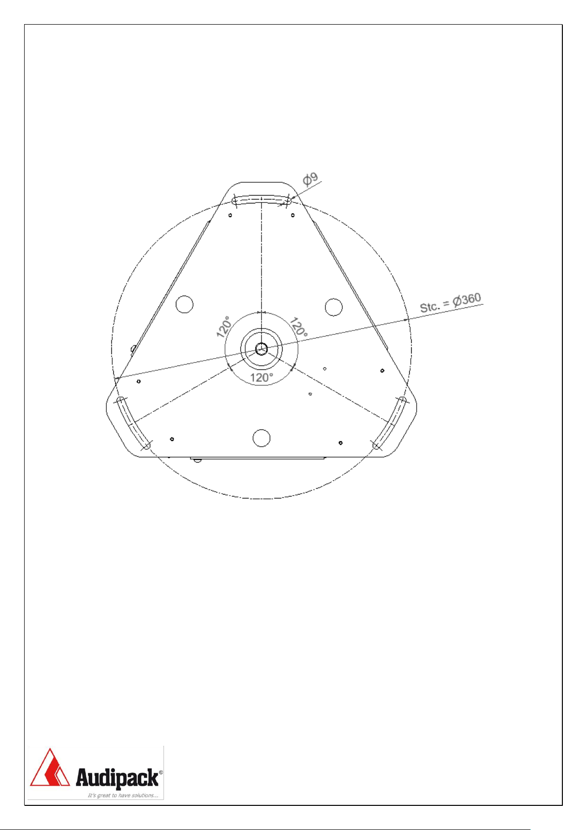
4.2 Mounting on ceiling
4.2.1 Drilling hole pattern
4.3 Mounting to false ceiling
When mounting to false ceiling, make sure a strong enough support exist to
handle the max load of PRK and monitor/projector combined.
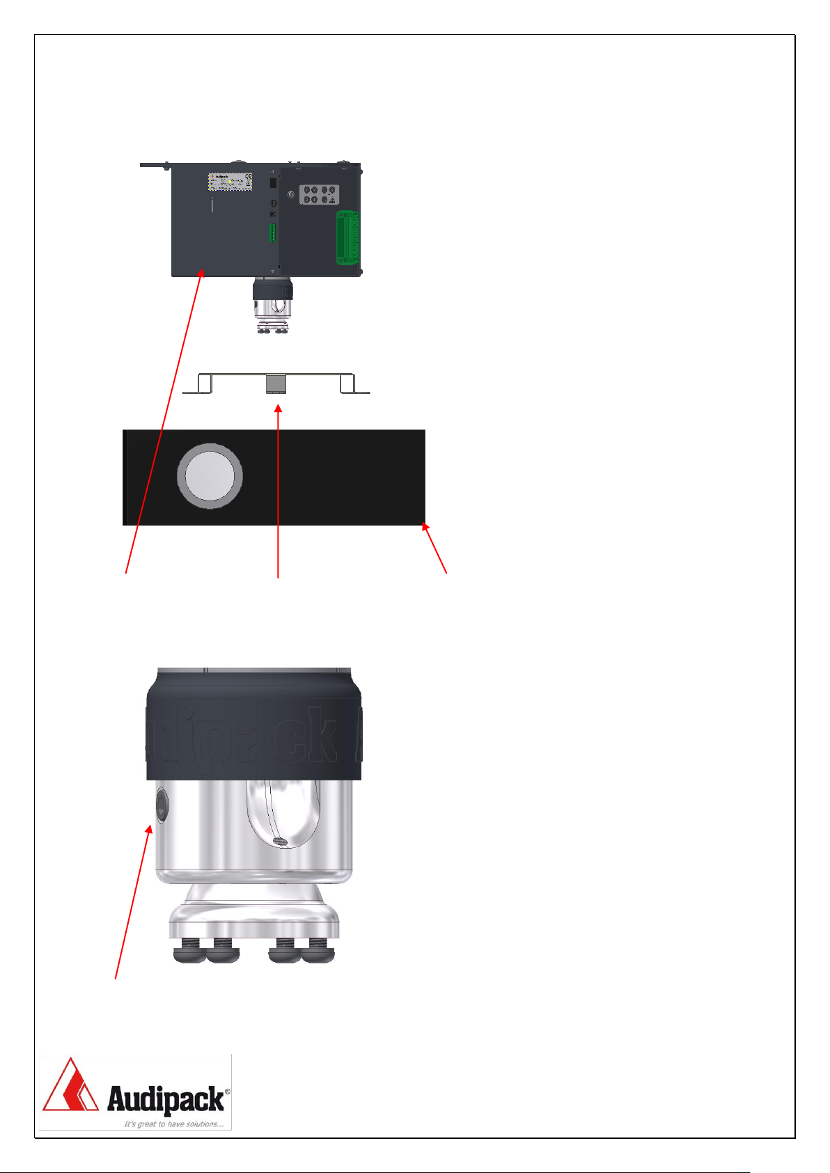
4.4 Mounting the monitor/ projector
4.4.1 Prerequisites of the monitor/ projector (Monitor/ projector info)
Mounting a monitor or projector on the PRK can only be accomplished using a
mounting plate that is suitable.
Assembling
9
PRK Mounting bracket Projector
4.4.2 Adjusting the projector.
To adjust the monitor or projector can be done as follows.
Loosen the hex screw, adjust to desired position and fasten hex screw.

Initial Setup
10
5Required for installation
5.1 Homing
If the control board will be used with position control the reference or home
position have to be set.
Position control is available on program number “1”, “2”, “3” en “5”.
5.1.1 The procedure for homing is as follows:
The motor runs in low speed to down limit switch
The motor stops when the (down) limit switch is activated
The motor runs in low speed in de reverse direction
The motor stops 10 count after the (down) limit switch is deactivated
!! In program number “5” homing is in the opposite direction !!
(limit switch “UP” will be activated)
5.1.2 Homing can be activated by:
Keypad +
RS-232 home, enter
Program number “2” auto homing
Motor control by input terminals
11
6Connection to mains
Never use damaged devices. Before mounting the PRK check the specifications
on the label with those of the local power supply. Do all mounting and
maintenance works with the power supply switched of.
Motor control by input terminals
12
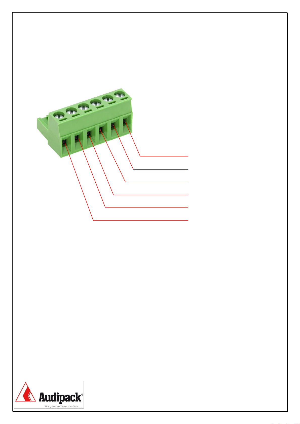
7Control by inputs 6-pole connector
M1
M2
M3
M4
SET
COM
7.1 Moving to memory positions
Move to memory position 1 make a connection between COM + M1
Move to memory position 2 make a connection between COM + M2
Move to memory position 3 make a connection between COM + M3
Move to memory position 4 make a connection between COM + M4
7.2 To set a memory position
To set a memory position:
Make an interconnection between COM + SET
Maintain this interconnection, and
Make an interconnection between COM + M1, M2, M3 or M4,
depends on the memory you want to store.
Disconnecting all the above connections will set the required memory
position. (an audible “click” is notable)

Motor control by input terminals
13
8Control by inputs 5-pole connector
The connection of the jumper can be replaced by a safety or emergency contact.
Removing the jumper completely disconnect the power from the control board.
8.1 Moving to memory positions
Move to memory position 1 or down/left direction make a connection between
COMMON and DOWN.
Move to memory position 2 or up/right direction make a connection between
COMMON and UP.

Motor control by RS-232
14
9Control by RS-232 serial communication
9.1 Connection of the RS232
9.2 Moving the lift by serial communication (RS-232)
Moving up = “o” enter (alphabetic letter)
Moving down = “n” enter (alphabetic letter)
To M1 = “m1” enter
To M2 = “m2” enter
To M3 = “m3” enter
To M4 = “m4” enter
For more information see register manual 1.1 and 1.2

Motor control by RS-232
15
10 Control by wireless remote
To control the Rota-Kit by wireless remote the next options are possible.
2 programmable projection positions
Use IR remote 260214, or use radio 868 Mhz RF remote 260215 for internal
installation.
The receiver pcb will be installed inside the PRK.
4 programmable projection positions
Use IR remote 260214, or use radio 868 Mhz RF remote 260215 for internal
installation. 1 receiver pcb will be installed inside the PRK and 1 external receiver
will be installed to the connector of the PRK.
Use external IR remote 260218, or use radio 868 Mhz RF remote 260219 for
external installation. 1 receiver pcb will be installed inside the PRK and 1 external
receiver will be installed to the 8-way connector of the PRK.
11 Control by wireless remote 2-positions
Open the PRK by removing the panel with the green connector. Undo the
keyboard connector from the PCB.
On the PCB 260192 select the desired channel (1is standard).
Install the receiver PCB on the 261377 in the small connector between the white
PCB holders (see image).

Motor control by RS-232
16
Insert the batteries in the hand remote and test the product after closing up the
PRK. Lead the antenna or IR receiver cable outside the PRK.
12 Control by wireless remote 4 positions
Install the internal PCB as mentioned before (see 11) or use 2 sets of below
listed external remotes.
Apply the external remote 260218 or 260219 and connect the PCB with the Up-
common-down connection to the 8-way external control connector on the PRK.
On the PCB 260192 inside the 260218 or 260219, select the desired channel
(2is standard for position 3&4 for the PRK). Connect C+3+4.

General information
17
13 General information
13.1 Definitions
Homing - Move motor to zero or reference point (counter)
Twin mode - Parallel or synchronous mode for 2 separate drive units
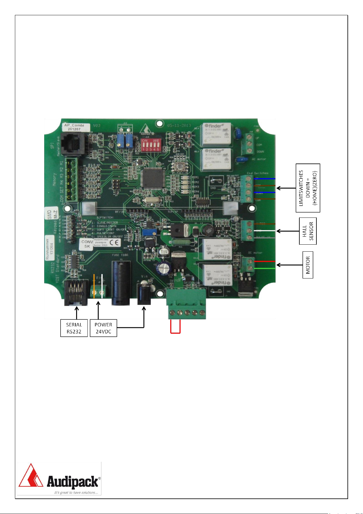
13.2 End switches
End switches, also called limit switches restrict the movement of the motor in
both directions.
The limit switches are related to the rotation direction of the motor.
It is important to connect the motor so that the direction of motion corresponds
to the controls and limit switches.
In any case the movement stops on both switches, but when the motion
direction and limit switch do not match, the two led’s (U2 and U3) of the
corresponding limit switches on the PCB start blinking.
13.3 Memory positions and directions
The memory positions M1 to M4 must be set in a specific order in between the
two limit switches. They differ of the selected program and are also related to the
buttons of the remote control.
Program “0” and “4”
M1 correspond with the left/down direction
M2 correspond with the right/up direction
M3 is not assigned
M4 is not assigned
Program “1”
M1 correspond with the left/down memory position between M3 and M4, and
down position of the RC (free programmable)
M2 correspond with the right/up memory position between M3 and M4, and up
position of the RC (free programmable)
M3 lowest memory position, close to limit switch down (factory setting)
M4 upper memory position, close to limit switch up (factory setting)
Program “2”, “3” and “5”
M1 correspond with down position of the RC (free programmable)
M2 correspond with the up position of the RC (free programmable)
M3 memory position is free programmable
M4 memory position is free programmable

General information
18
13.4 Memory position control
Memory position M1 to M4 can be set in three different ways.
By the keypad on the electrical control box
By the memory and motor control terminal
By serial communication via RS-232
In program number “1” M3 and M4 are protected and can only be stored using a
PIN-code.
Set the memory position by the keypad
13.5 Error reset
All errors can be reset by disconnecting the power from the control board.
Take at least 10 seconds to power up.
The only exception is if two control boards are in twin mode.
If an synchronous error occurs then both motors have to be reset and homed
separately. Taking into account of mechanical damage.
Settings
19
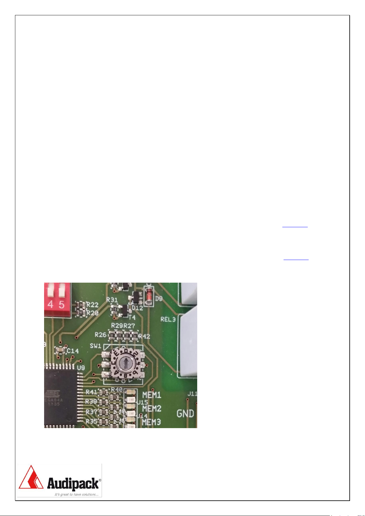
14 Program rotary switch (SW1)
14.1 Precautions
Before changing the program state disconnect the power from the control board.
Set memory positions under load. Place the projector or flat screen before
storing the memory positions.
14.2 Rotary switch positions versus functions
Rotary switch on position “0” = DC motors up to 30VDC without position control
Rotary switch on position “1” = DC motors up to 30VDC, column lifts with intern
limit switches and position control.
Rotary switch on position “2” = DC motors up to 30VDC with external limit
switches and position control, auto homing.
Rotary switch on position “3” = DC motors up to 30VDC with external limit
switches and position control, manual homing.
Rotary switch on position “4” = Single phase AC tube motors with external limit
Switches .
Rotary switch on position “5” = Single phase AC tube motors with external limit
Switches and position control, manual homing.
(4 & 5 not applicable on PCB 261377)
Settings
20
14.3 Rotary switch positions versus product examples
Rotary switch on position “0” = MKT-150WS, MKT-200WS, MKT-250WS,
MKT-265WS
Rotary switch on position “1” = FFCL-XXXX, Column lifts
Rotary switch on position “2” = PRK-250, PRK-500, PRK-750, PCL-M350,
PCL -X350 and MKT-C150
Rotary switch on position “3” = PRK-250, PRK-500, PRK-750, PCL-M350,
PCL -X350 and MKT-C150
Rotary switch on position “4” = Universal AC tube motors
Rotary switch on position “5” = PCL-1070, PCL-2050, PCL-3050, PCL-5050
Switches and position control, manual homing.
(4 & 5 not applicable on PCB 261377)
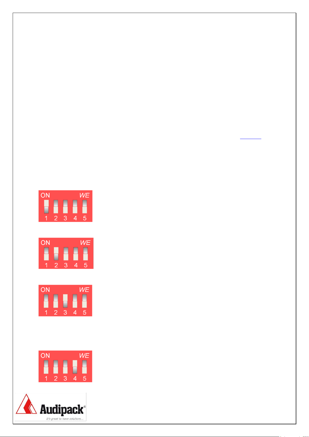
15 Function dipswitches (J14)
Dipswitch position 1 = Master/slave - slave “on” (in twin-mode only)
Dipswitch position 2 = Single/twin - single mode “on”
Dipswitch position 3 = Soft start/stop on/off - soft start/stop “on”
Dipswitch position 4 = Pulse/continue - pulse “on”
!! When pulse is “on”, the direction buttons are working as a latching switch !!
This manual suits for next models
2
Table of contents
Other Audipack Projector Accessories manuals


Popular Projector Accessories manuals by other brands


Christie
Christie Vivid Blue 38-VIV301-01 instructions

Pen Laboratory
Pen Laboratory Smart Sheet user manual

PEERLESS
PEERLESS PRG-UNV-S Installation and assembly

Monoprice
Monoprice 15495 user manual

Premier Mounts
Premier Mounts PSD-VHSA installation manual

PEERLESS
PEERLESS PSM-UNV Installation and assembly
 user manual")
Black Box
Black Box Wireless HDMI Presentation System (WHPS) user manual

Claypaky
Claypaky C52323 operating instructions

Omnimount
Omnimount 3N1-PJT instruction manual

Omnimount
Omnimount OM1004108 instruction manual

Black Box
Black Box Wireless Video Presentation System III... Quick installation guide

Panasonic
Panasonic ET-D75LE8 Spec file