Audison Prima APSP G6 User manual

rev. 1
INSTALLATION
MANUAL
APSP G6


APSP G6 /
3
INSTALLATION MANUAL
Table of Contents
1. PRODUCT DESCRIPTION .......................................................................................................................................................5
2. CONTENTS OF THE PACKAGE...............................................................................................................................................6
3. TECHNICAL SPECIFICATIONS...............................................................................................................................................7
3.1 Pre-set description ........................................................................................................................................................... 7
4. CONNECTIONS LAYOUT .........................................................................................................................................................8
5. REMOVING THE ORIGINAL CAR RADIO..............................................................................................................................9
5.1 Removing the nishing frame........................................................................................................................................ 9
5.2 Removing the 4 fastening screws ................................................................................................................................9
5.3 Extraction of the original car audio...............................................................................................................................9
6. DISASSEMBLING THE CAR DOOR SILL AND COVERINGS FROM THE RIGHT SIDES..........................................10
6.1 Removing the rear seat .................................................................................................................................................10
6.2 Removing the right rear wheelhouse cover (5-door version)................................................................................11
6.3 Removing the right door sill completely ....................................................................................................................12
6.4 Removing the lower cover of the right pillar .............................................................................................................13
6.5 Removing the right side covering of the dashboard ...............................................................................................13
7. DISASSEMBLING THE FRONT DOOR COVERING...........................................................................................................14
7.1 Removing the front door panel....................................................................................................................................14
7.2 Removing the tweeter casing ......................................................................................................................................15
8. PASSING APSP G6 HARNESS CABLES...........................................................................................................................16
8.1 Passing the cable in the car radio's casing to the right of the dashboard..........................................................16
8.2 Passing the subwoofer power cable up to the left rear side of the boot ............................................................17
9. INSTALLATION OF SUBWOOFER APBX G6......................................................................................................................18
9.1 Installing the mounting kit ............................................................................................................................................18
9.2 Installing APBX G6 in the car........................................................................................................................................19
9.3 APBX G6 installation completed..................................................................................................................................20
10. INSTALLATION OF WOOFERS AP 6.5 G6 .........................................................................................................................21
10.1 Removing original Woofers ..........................................................................................................................................21
10.2 APSP G6 SPEAKER CABLE connection to woofer AP 6.5 G6...............................................................................22
10.3 Assembling the woofer into the casing......................................................................................................................22
11. INSTALLATION OF TWEETER AP 1 SP..............................................................................................................................23
11.1 Removing the original Tweeters from the casing ....................................................................................................23
11.2 Installing the AP 1 SP MOUNTING KIT ......................................................................................................................23
11.3 Installing AP 1 SP in the casing ...................................................................................................................................24
12. INSTALLATION OF AP 8.9 BIT G6.......................................................................................................................................25
12.1 Install ASP (Automatic Speaker Presence) ...............................................................................................................25
12.2 APSP G6 HARNESS cable connection to AP 8.9 bit G6 .........................................................................................25
12.3 Positioning AP 8.9 bit G6...............................................................................................................................................25
13. CONNECTION OF THE APSP G6 HARNESS CABLE TO THE ORIGINAL CAR RADIO ............................................26
13.1 Connect the APSP G6 HARNESS cable.....................................................................................................................26
14. REASSEMBLING ALL PARTS...............................................................................................................................................26
14.1 Reassemble all parts of the vehicle by following the operations described in
the disassembly section in reverse order......................................................................................................26
15. OPTIONAL ACCESSORIES....................................................................................................................................................27
15.1 DRC (Digital Remote Control).......................................................................................................................................27
15.2 DRC-MP (Digital Remote Control)...............................................................................................................................27
15.3 Bit Play HD........................................................................................................................................................................27
15.4 OP 1.5 TOSLINK OPTICAL CABLE 1.5 M / 59.05 IN.................................................................................................28
15.5 OP 4.5 TOSLINK OPTICAL CABLE 4.5 M / 177.16 IN...............................................................................................28
15.6 STA - F/F SOCKET TOSLINK ADAPTER.....................................................................................................................28
15.7 ECK DRC ...........................................................................................................................................................................28
16. TROUBLESHOOTING..............................................................................................................................................................29

APSP G6 /
4
INSTALLATION MANUAL
Introduction
Congratulations for having purchased one of our products. Your satisfaction is the sine qua non that
our products must meet: the same satisfaction of anyone who wants to feel the thrill of a car radio.
This manual was drawn up to provide important information required to install and use the system.
Before installing the devices, carefully read all the instructions in this manual, and the manuals regarding
individual parts included in the relative packages. Failure to comply with these instructions can cause
involuntary injury or damage to system's parts or the vehicle.
Warranty
For the warranty conditions, please visit www.audison.eu or contact your specialised Audison centre.
Safe sound
USE COMMON SENSE WHEN LISTENING TO THE RADIO. REMEMBER THAT PROLONGED EXPOSURE
TO EXCESSIVE LEVELS OF SOUND PRESSURE CAN DAMAGE YOUR HEARING. SAFETY WHEN DRIVING
MUST ALWAYS BE FIRST.

APSP G6 /
5
INSTALLATION MANUAL
1. PRODUCT DESCRIPTION
APSP G6 was specifically designed for VW Golf 6(*) and comprises:
1. An AP8.9 bit G6 amplifier equipped with bit Drive technology and integrated with 7 drive pre-set dedicated to
VW Golf 6(*) designed by the Audison R&D team for “Plug&Sound” performance. The 7 “Drive preset” pre-
loaded in the AP8.9 bit G6 memory enables you to use to product without PC connection. Pre-set is chosen
based on the user's preferences. AP8.9 bit G6 is equipped with DCC-Direct Cockpit Current technology and is
powered directly from the rear connector of the OEM source.
2. An APBX G6 passive closed-box subwoofer, which contains a compact speaker APS 250. The box is specifically
designed to be placed on the left side of the boot, and is very compact in size and is fixed to the car without
drilling the chassis. The mounting kit and installation manual are in the package.
3. A front two-way system that includes the AP 6.5 G6 woofers, AP 1 SP tweeters and specific crossovers,
adapters to set up OEM for the speakers, connectors, and gaskets for perfect integration with the pillars.
4. A complete set of special cables for the car and kit, designed with Plug&Sound technology to be connected
to original car manufacturer connectors, without needing to change the original car cables.
5. A special APSP G6 Harness that draws power of AP8.9 bit G6 directly from the rear connector of the OEM source.
The kit is designed to be installed on a VW Golf 6(*) in less than 2 hours; this time can vary according to the conditions
and equipment of the vehicle.
Note: • All kit components have been designed to be attached to the manufacturer's original attachment points on the vehicle.
• Pay special care during the removal and insertion of the speakers' xing rivets.
• Make sure all the gaskets supplied with the speakers are positioned correctly and are working perfectly.
• The connectors are fragile components and must be handled with care.
• After installation and before restarting the system, make sure the equalization of the vehicle's radio is flat.
• Install the kit components by following the instructions to ensure they do not prevent airbags or other safety devices of
the car from working correctly.
• Use suitable quality equipment to simplify, accelerate and achieve optimal installation.
These installation instructions are updated to revision 01. Additional documents can be downloaded from www.audison.eu.
If there is a malfunction during installation of the kit, check the section regarding “TROUBLESHOOTING” at the end of this manual.
If you have consulted the aforesaid section and are still unable to solve the problem, visit www.audison.eu or contact your Audison
authorised, specialised centre or ofcial assistance via email: [email protected].
*Golf is a registered brand that is property of Volkswagen.
WARNING: Before proceeding with installing, make sure the APSP G6 kit is compatible with the version of your
VW Golf.
All the information and images contained in this manual are referred to the left-hand drive 5-door car.
1

APSP G6 /
6
INSTALLATION MANUAL
2. CONTENTS OF THE PACKAGE
2
AP 6.5 G6
AP 6.5 G6 MOUNTING KIT
AP 6.5 G6 RING
x 10x 8
x 2x 2
AP 8.9 bit G6
x 1 x 1
2,6 m / 98.43 in.
1,8 m / 70.87 in.
295 mm / 11.61 in.
645mm / 25.39 in.
250 x 250 mm / 9.84 x 9.84 in.
ASP
SETUP CD
SCREWS
4,2 mm x 50 mm
0.17 in. x 1.97 in.
FUSE 30A
CAVO USB
QSG WARRANTY HEX KEY
2,5 mm / 0.1 in.
VELCRO
175 mm x 6.89 in.
x 1
x 1
x 4 x 1x 1
x 1 x 1 x 1
APSP G6 HARNESS
APGSP G6 SPEAKER CABLE
x 1
WF
TW
x 2
DAMPING PANEL
APBX G6 MOUNTING KIT
x 1
x 6
x 1x 1
x 1
APBX G6
x 1
AP 1 SP
x 2
x 2
AUDISON BADGE
AP 1 SP MOUNTING KIT
x 2
x 6
x 2
AP 8.9 bit
QUICK
START
GUIDE
AP8.9
CD 1.0A
30 A

APSP G6 /
7
INSTALLATION MANUAL
3. TECHNICAL SPECIFICATIONS
Component APSP G6 - Front
2 WAY SYSTEM
APBX G6
SUBWOOFER
Size mm (in.) Woofer 165 (6.5)
Tweeter 26 (1) 250 (10)
Power Handling W (peak) 300 900
W (continuos) 100 300
Impedance Ω4 4
Frequency
Response Hz 60 ÷ 20k 38-350
Crossover type 2-Way passive Digital
T
ECHNICALSPECIFICATIONS
Channel Mode Speaker Power
1-2 3-4 Bridge APSP G6 - Front 2 x 130W RMS @ 4Ω
5-6 Stereo OEM Rear Speakers 2 x 35W RMS @ 4Ω
7-8 Bridge APBX G6 - Subwoofer 1 x 130W RMS @ 4Ω
AP8.9 bit OUTPUT CHANNEL MAP
Component APSP G6 - Front
2 WAY SYSTEM
APBX G6
SUBWOOFER
Size mm (in.) Woofer 165 (6.5)
Tweeter 26 (1) 250 (10)
Power Handling W (peak) 300 900
W (continuos) 100 300
Impedance Ω4 4
Frequency
Response Hz 60 ÷ 20k 38-350
Crossover type 2-Way passive Digital
TECHNICALSPECIFICATIONS
Channel Mode Speaker Power
1-2 3-4 Bridge APSP G6 - Front 2 x 130W RMS @ 4Ω
5-6 Stereo OEM Rear Speakers 2 x 35W RMS @ 4Ω
7-8 Bridge APBX G6 - Subwoofer 1 x 130W RMS @ 4Ω
A
P8.9 bit OUTPUT CHANNEL MAP
3.1 Preset description
PRESET
LISTENING POSITION
YOUR SOUND
DETAILS
Overall FLAT This preset only contains standard lters; no equalizations and no
time alignments have been applied.
WARNING: Preset “0” contains the input/output congurations dedicated to this speakers system.
The “factory default” function loses the pre-loaded preset in “0”. For this reason you must restore correct input/output
setting via AP Prima PC software. It is recommended to backup the preset in your PC.
Failure to comply with these recommendations can cause irreparable damage to AP8.9 bit G6 as well as products connected to it.
DO NOT CHANGE PRESET WHEN THE PRODUCT IS ON.
Left Hand Drive Acoustic
Detailed mid-high frequencies with perfectly balanced bass. Time
alignment have been calibrated to ensure the best listening sensation
for the driver (Left-hand drive cars).
Left Hand Drive Live
Crisp mid-high frequencies and really dynamic bass.
Time alignments have been calibrated to ensure the best listening
sensation for the driver (Left-hand drive cars).
Left Hand Drive Rhythm
Detailed mid-high frequencies with punchy bass. Time alignments
have been calibrated to ensure the best listening sensation for the
driver (Left-hand drive cars).
Right Hand Drive Acoustic
Detailed mid-high frequencies with perfectly balanced bass. Time
alignment have been calibrated to ensure the best listening sensation
for the driver (Right-hand drive cars).
Right Hand Drive Live
Crisp mid-high frequencies and really dynamic bass.
Time alignments have been calibrated to ensure the best listening
sensation for the driver (Right-hand drive cars).
Right Hand Drive Rhythm
Detailed mid-high frequencies with punchy bass. Time alignments have
been calibrated to ensure the best listening sensation for the driver
(Right-hand drive cars).
(default)
Overall Acoustic
Detailed mid-high frequencies with perfectly balanced bass. Time
alignments have been set-up to guarantee the better listening feeling
for everybody in the car.
Notes:
- The AP 8.9 bit G6* is delivered with the selector set on pre-set “7” (Overall – Acoustic).
- You can install the “AP Prima PC Software” program in “Prima Amplier Setup CD”.
* Refer to the operating manual regarding AP8.9 bit for detailed information relating to installation and use of the “AP Prima PC Software”.
All materials are available from www.audison.eu.
01
2
3
4
5
6
7
POWER - 12V USB
OPTICAL SEL.
1 2 3 4 5 1 2 3 4 5 6
76 8
UPGRADEPRESETS
SPEAKER
OUT
OPTICAL IN DRC
SUB OUT
INPUTS
ASP
OFF ON
REM IN
REM OUT
MASTER ENABLE
30A
1
2
3
4
5
6
70
3
1
2
3
4
5
6
70
1
2
3
4
5
6
70
1
2
3
4
5
6
70
1
2
3
4
5
6
70
1
2
3
4
5
6
70
1
2
3
4
5
6
70
1
2
3
4
5
6
70
1
2
3
4
5
6
70
APSP G6 /
8
INSTALLATION MANUAL
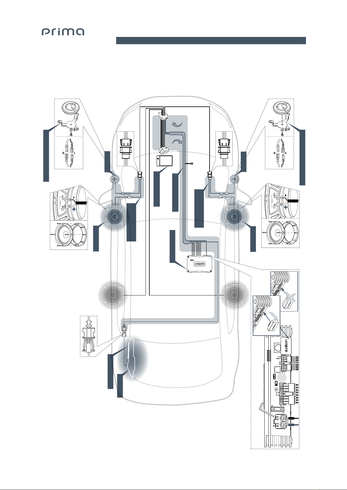
OEM HEADUNIT
Ch 1/2 (Bridge)
Ch 7/8
(Bridge)
Ch 5
Ch 6
Ch 3/4 (Bridge)
+ BATT
(DCC)
- GND
AP 6.5 G6
APBX G6
Damping panel
AP 6.5 G6
AP8.9 bit G6
AP 1 SP
AP 1 SP Mounting kit
01
2
3
4
5
6
7
POWER - 12V USB
OPTICAL SEL.
1 2 3 4 5 1 2 3 4 5 6
76 8
UPGRADEPRESETS
SPEAKER
OUT
OPTICAL IN DRC
SUB OUT
INPUTS
ASP
OFF ON
REM IN
REM OUT
MASTER ENABLE
30A
ASP NO
ASP OK
AP 1 SP
AP 1 SP Mounting kit
APSP G6 Harness
APSP G6
SPEAKER CABLE
APSP G6
SPEAKER CABLE
4. CONNECTIONS LAYOUT
4

APSP G6 /
9
INSTALLATION MANUAL
5. REMOVING THE ORIGINAL CAR RADIO
5.1 Removing the nishing frame
5.2 Removing the 4 fastening screws
5.3 Extraction of the original car radio
WARNING: Remove the key from the car's ignition and pull the lever to release the bonnet.
Close the doors and wait for 5 minutes, then open the bonnet and disconnect the negative pole
from the car's battery.
Fig. 1
Fig. 2
5
5.3.1 disconnecting all connectors from the rear.

APSP G6 /
10
INSTALLATION MANUAL
6. REMOVING THE DOOR SILL AND COVERINGS FROM THE RIGHT SIDE
6.1 Removing the rear seat (Fig. 3 point 1)
6.1.1 Remove the four plastic covers from the Isox anchoring device of the rear seat (Fig. 3 point 2 / 3).
6.1.2 Lift the front part of the seat (Fig. 3 arrow A) to release the 2 stops (Fig. 3 point 4).
6.1.3 Push the bench seat back (arrow B) and lift it from the rear, then remove it from the vehicle.
1
A
A
B
4
3
2
Fig. 3
6
WARNING: The procedure shown below describes the right side of the vehicle. Proceed in a similar manner
for the left side.

APSP G6 /
11
INSTALLATION MANUAL
6.2 Removing the right rear wheelhouse cover (5-door version)
6.2.1 Tip the right backrest forward to access the wheelhouse cover.
6.2.2 Remove the cap from the upper part of the covering (gure 4) with a plastic lever.
6.2.3 Remove the two screws (Fig. 5).
Fig. 4
Fig. 5
2
1
6

APSP G6 /
12
INSTALLATION MANUAL
6.2.4 Partially remove the gasket from the right door until the wheelhouse covering is free.
6.2.5 Remove nut 1 from bolt 2(Fig. 6).
6.2.6 Remove the covering from the body (Fig. 6 point 3).
6.3.1 Lift the front part of the door sill and release the fastening clip.
6.3.2 Release the guide from the lower part of the covering of the central pillar (Fig. 7 point 1).
6.3.3 Lift the rear part of the door sill and release the fastening clip.
6.3.4 Release the guide from the lower part of the covering (Fig. 7 point 3).
6.3.5 Release the tab and extract the safety belt (Fig. 7 point 2).
3
2
1
B
B
A
1 2 3
Fig. 6
Fig. 7
6.3 Remove the right wheelhouse completely (Fig. 7)
6

APSP G6 /
13
INSTALLATION MANUAL
6.4 Removing the lower cover from the right pillar (Fig. 8).
6.4.1 Remove the covering with a lever and extract it, as shown by arrows A and B.
6.2.4 Partially remove the gasket from the right door until the wheelhouse covering is free.
B A
Fig. 8
6.5 Removing the right side covering of the dashboard (Fig. 9).
1
A
Fig. 9
6.5.1 Insert a plastic lever (A) into reference catch 1 and gently force it to the right to
release the fastening clip.
6
APSP G6 /
14
INSTALLATION MANUAL
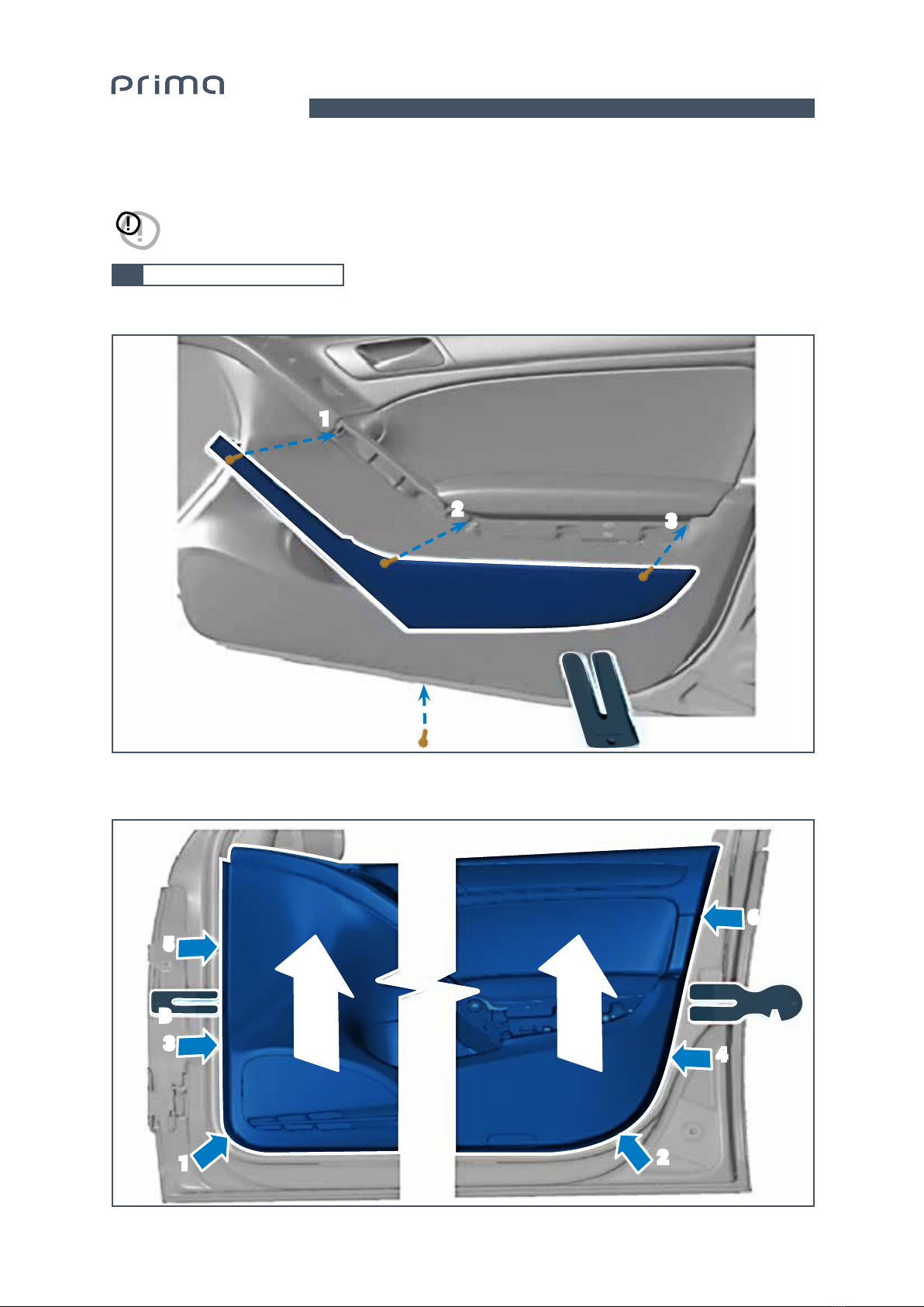
7. REMOVING THE FRONT DOOR COVERING
7.1 Removing the front door panel
7.1.1 Remove the door covering grille using a plastic lever, then loosen screws 1, 2, 3 and 4 (Fig. 10)
A
Fig. 10
Fig. 11
7.1.2 Using a plastic lever, release all the covering clips according to the sequence shown (Fig. 11 ).
7.1.3 Lift the covering by rmly pulling upwards, as shown by arrow C in order to release it (Fig. 11).
WARNING: The procedure shown below describes the right side of the vehicle. Proceed in a similar manner
for the left side.
2
4
3
1
7
BA
5
6
34
12
CC

APSP G6 /
15
INSTALLATION MANUAL
7.2 Removing the tweeter casing
Fig. 12
7.1.4 Release the door opening control cable (Fig. 12 point 1).
7.1.5 Disconnect all cables from the door's covering.
7.2.1 Release the tweeter support from the three fastening caps using a plastic lever (Fig. 13 points 1, 2 and 3).
7.2.2 Disconnect the connector (Fig. 13 points 4).
7
4
Fig. 13
1
1
3
2

APSP G6 /
16
INSTALLATION MANUAL
8. PASSING THE APSP G6 HARNESS CABLE
8.1 Passing the cable from the car radio's casing to the right of the dashboard
Fig. 14
Fig. 16 A
Fig. 15
Fig. 16 B
8.1.1 Pass sections B, C, and D of cable APSP G6 HARNESS (Fig. 14) from the car radio (Fig. 15) compartment
above the glove compartment using a probe (Fig. 16 A).
8.1.2 Insert the cable towards the door sill and connect earth cable D into bolt E(Fig. 16 B).
A
D
C
B
8
E
APSP G6 HARNESS
WARNING: The procedure shown below describes the right side of the vehicle. Proceed in a similar manner
for the left side.

APSP G6 /
17
INSTALLATION MANUAL
- GND A
Fig. 17 Fig. 20
Fig. 19
Fig. 18
8.1.3 Lift the carpet from the floor in point A(Fig. 17) and insert cables C(Fig. 14) under the covering along
the slits provided in the carpet. Make sure that both the connectors and power supply cables
exit from the provided slots situated under the front right seat.
8.2 Passing the subwoofer power cable up to the left rear side of the boot
8.2.1 Insert the subwoofer's power cable B(Fig. 14) through passage A(Fig. 17), and run it along the
door sill and through the rear bench seat and proceed until the left wall of the boot (g. 18 -19); the
cable must exit from the provided slot (g. 20).
8

APSP G6 /
18
INSTALLATION MANUAL
9. APBX G6 SUBWOOFER INSTALLATION
STEP A
Insert one of the two screws
but do not tighten it.
Inserire una delle 2 viti ma
senza serrarla.
Tighten the 2 screws.
Serrare le 2 viti.
Tighten the 2 screws.
Serrare le 2 viti.
II
III
I
Fig. 21
9.1 Installing the mounting kit
9.1.1 Assemble the three brackets of the APBX G6 MOUNTING KIT onto the points provided on the box, strictly
following the instructions reported in the gure (Fig. 21).
9

APSP G6 /
19
INSTALLATION MANUAL
STEP B: from 1 to 6
2
1
Damping panel
*
*
*
3
6
34
6
5
5
Tighten the 2 screws.
Serrare le 2 viti.
4
ab
**
**
*Car hook / Gancio auto
If the anchoring hook equipped with the car is not like the one shown in the picture, it is neces-
sary to purchase one separately from a Volkswagen dealer. /Nel caso il gancio di ancoraggio,
di cui è quipaggiata la vettura non fosse come quello in foto è necessario acquistarlo separata-
mente presso una concessionaria Volkswagen
9.2 Installing APBX G6 in the car
9.2.1 After positioning the DAMPING PANEL (Fig. 22 point 1), connect connector (Fig. 22 point 2) and insert
brackets and of the box into the anchoring hooks of the boot (Fig. 22 points 3 and 4).
9.2.2 Place the box vertically (Fig. 22 point 5), rotate bracket and insert it into the anchoring hook
of the backrest. Then also assemble the second screw and lastly tighten both in order to
secure APBX G6 (Fig. 22 point 6 A/B).
Fig. 22
III
II
I
9

APSP G6 /
20
INSTALLATION MANUAL
Fig. 23
9.3 APBX G6 installation completed
9
Table of contents
Other Audison Automobile Accessories manuals

Popular Automobile Accessories manuals by other brands


Vision Systems
Vision Systems VS55020 user manual

Keith
Keith Running Floor II Metric installation manual

GEV
GEV KIT 49 Assembly instructions

Ridewell Suspensions
Ridewell Suspensions RAR-240 owner's manual

Baja Designs
Baja Designs 447575 instructions

Rago FABRICATION
Rago FABRICATION R2200TTUNBCM installation guide


