ECB BIG TUBE BG44SY User manual

.© Copyright –ECB Pty Ltd –2012 1
BG44SY
FITTING INSTRUCTIONS
GMC DENALI 2011on 2500 HD
WINCH COMPATIBLE BIG TUBE™BAR (WITH FOG LAMPS)
VEHICLE FRONTAL PROTECTION SYSTEM (VFPS)
FOR AIR BAG & ADR COMPLIANT VEHICLES
Check installation hardware before commencing.
1. Lift bonnet
2. Remove grille to radiator support cover, ten push pull plastic clips.
3. From air opening on bumper, disconnect air damming from front bumper. (Six plastic Christmas tree plugs.)
4. From front of wheel arch, remove 2 x 7mm head screws in infill trim under headlight. Gently pull sides away
from vehicle to unclip from guard clips, then forward whilst unclipping from bottom of grille between grille and
radiator support.
5. From under bumper, remove two 10mm nuts from inner guards to bumper (per side) and two 7mm head screws
from wheel arch side of bumper. (per side)
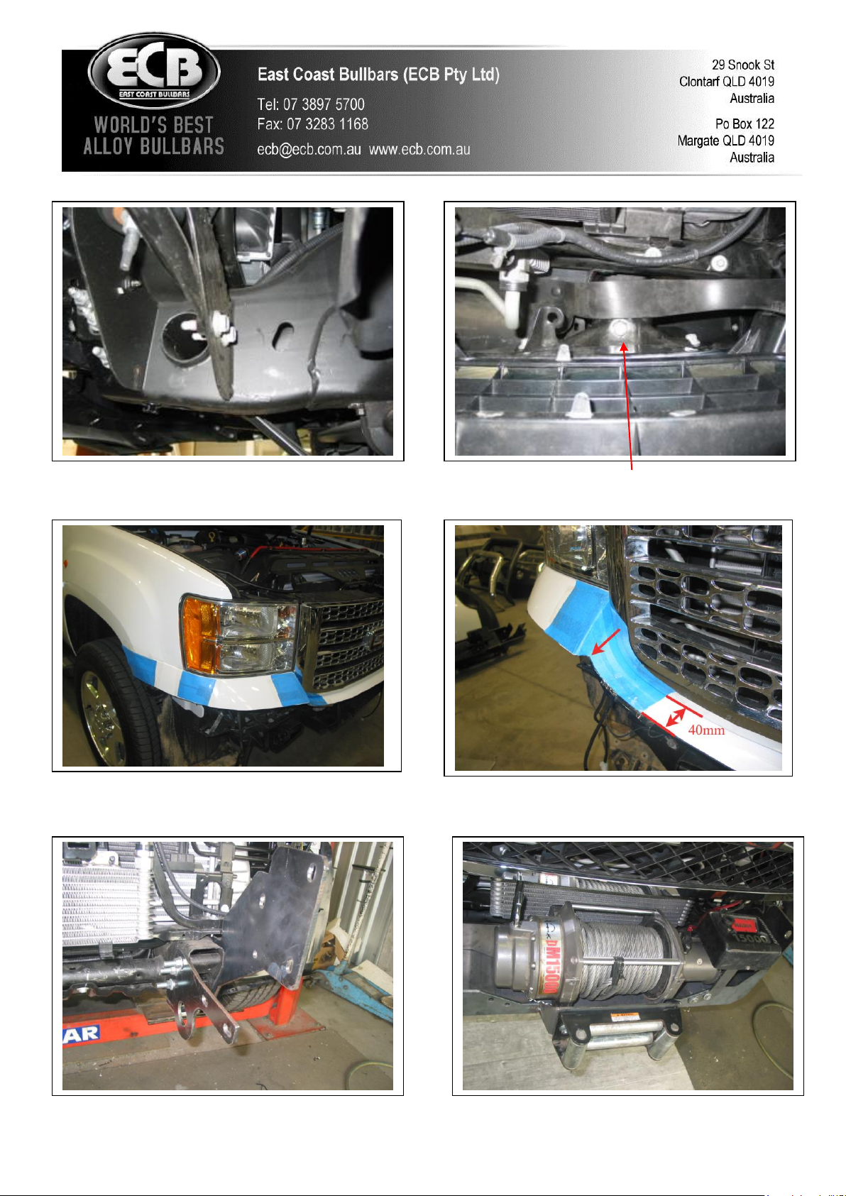
6. Remove bumper stays. One 15mm bolt (per side) from bumper end and two 15mm bolts (per side) from chassis
end. See figure 1. Disconnect fog lights.
7. Remove two 21mm bolts from bumper brackets. Access from behind grille. See figure 2.
8. Remove bumper from vehicle.
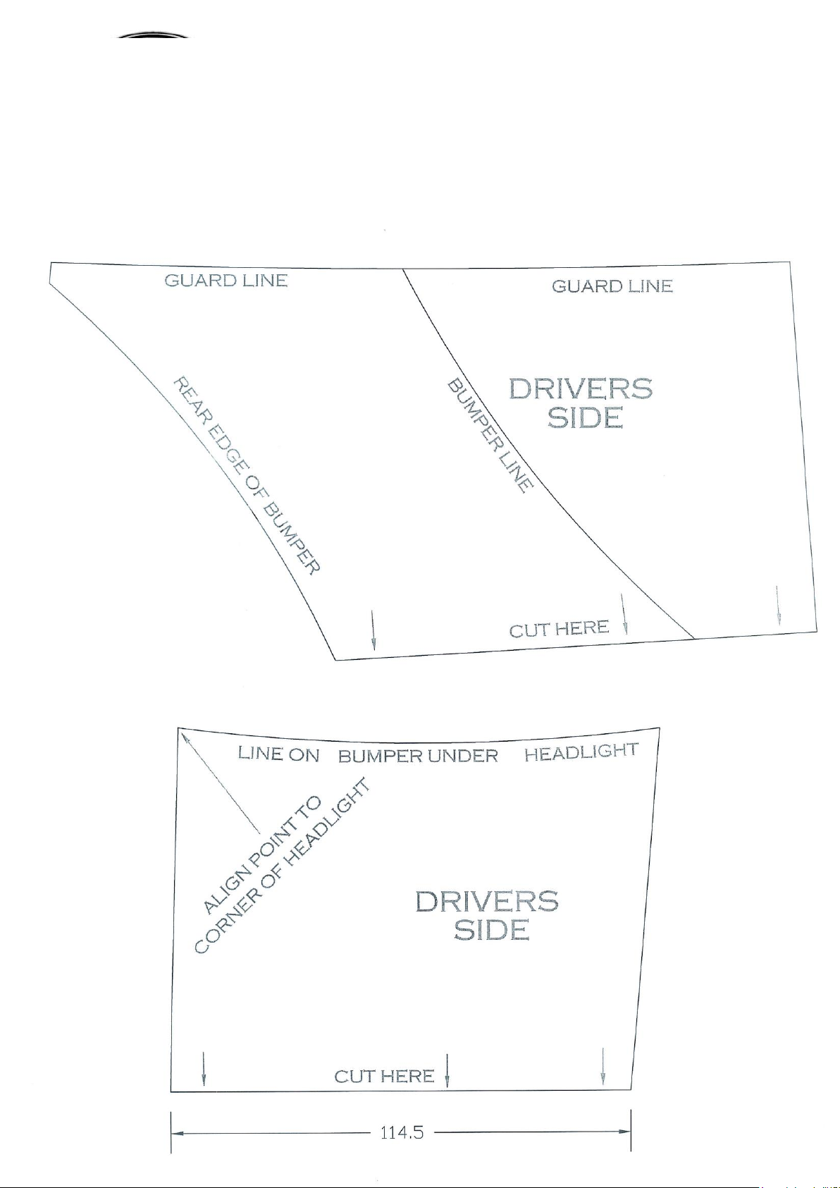
9. Refit original equipment infill trim to vehicle. Measure infill templates for correct sizing. Caution: Check size
of templates as size may vary according to printer. Using a sharp pair of scissors, cut templates to shape. Mask
required area of vehicle. Using pre-cut templates, mark cut line on infill area. See figure 3. Measure 40mm from
front of grille to cut line under grille. See figure 4. Join marked lines together using a straight line neatly.
10. Double check cut line to template before cutting. Cut neatly on masked line. Caution: Infill area has plastic
support under. Cutting bumper will dislodge and remove some of these supports. Remove if become dislodged.
Bumper will retain shape with the supports no longer attached.
11. Attach 3mm clip lock trim to underside of outer cut section of original equipment infill. Cut rear of 3mm clip
lock trim to suit rear edge of infill and inner edge of rear shorter to allow for material in bend of plastic.
12. Remove bumper brackets and tow hook from front of chassis rails (two 21mm nuts on factory “u” bolts) and one
19mm bolt and nut and 19mm anti twist bolt from tow hook.
13. Fit ECB Steel inner mounting brackets (supplied) to inside of chassis rails using three ½ x 5 ½ bolts and flat
washers and one 1 x 1 ½ bolt, flat washers, spring washers and nut (per side)(supplied). Fit ECB Steel outer
mounting brackets to outside of chassis rail. Attach using flat washer, spring washer and nut (supplied). On lower
bolt place space tube on inside of chassis rail over bolt. See figure 5. Tighten bolt on underside of chassis only.
REPLACES: 00.00.00
REVISED: 12.09.11
.

.© Copyright –ECB Pty Ltd –2012 2
14. Fit fairlead rollers to side of winch frame with rectangular cut out using ½ x 1 ¼ bolt flat washers, spring
washers and nut (supplied) (place bolt through from inside to front of mount).
15. Remove lower tie bar from winch and refit to back of winch using 6mm Allen key. Place winch into winch frame
so Winch rope will feed from underside of winch. Attach to underside of winch frame using four 7/16 x 1 ½
bolts, flat washers and spring washers supplied with winch. Fit two 7/16 x 1 ½ bolts, flat washers and spring
washers (supplied) to winch from rear of winch frame. Ensure wire winch rope is passed through fairlead rollers
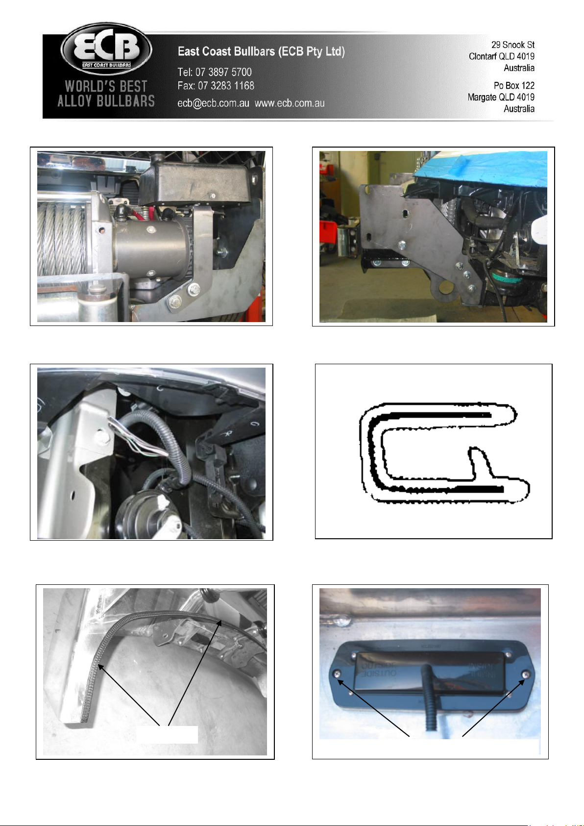
upon installation of winch. Fit hook to wire rope. See figure 6.
16. For 12,000lb Warn Winch - Fit control box to winch motor. Clamp in position with large hose clamps (supplied
with winch) socket on control box mounted vertically on winch. Connect cables to motor as indicated.
17. For 15,000lb Warn Winch –Fit ECB control box bracket (supplied) to winch mounting bracket. Use two 3/8 x
1 ¼ bolts, nuts, flat and spring washers (supplied). TIGHTEN roller fairlead. Bolt control box to ECB bracket
using original nuts. TIGHTEN IN POSITION. Connect cables to motor as indicated in winch instructions. See
figure 5.
18. With the help of a second person, place winch frame onto inner steel mounting brackets, between outer steel
mounting brackets. Attach to mounts using four ½ x 1 ½ bolts, flat washers, spring washers and nuts (supplied)
on lower points of mounts and one ½ x 1 ½ bolts, flat washers, spring washers and nuts (supplied) into outer steel
mounting brackets. Align holes from winch frame to outer steel mount and tighten all bolts on inner steel mount
only. See figure 6. WARNING: Winch and frame are very heavy, two person lift is required.
19. Feed winch wiring to battery. Ensure wiring is protected from sharp edges and other damage. Test winch for
correct operation.
20. Splice ECB indicator/park light and fog light wiring into original wiring loom. Use cable locks (supplied).
Wiring is accessible under headlamps. If original fog lamps not fitted, an accessory wiring kit will be required.
See figure 7.
21. Attach 6mm clip lock trim (supplied) to top of ECB protection bar. NOTE: Trim off lower edge on an angle so
trim will sit flush with end of protection bar. See figures 8 and 9.
22. Attach 6mm clip lock trim (supplied) to inner edge of skirt cut out for winch. Trim to suit opening.
23. Fit ECB LED indicator / park lights (supplied) into protection bar as per instructions supplied with the LED
indicator kit. NOTE: Ensure park light is to outside. See figure 10.
24. Attach ECB fog lights to protection bar. Place M6 x 20 bolts, spring washers (supplied) through light mount
from inside and attach nut to top. Slide assembly into light mount in Protection bar and centralize light to hole.
See figure 11. Tighten Firm Only. NOTE: Do not fit ECB light trims to protection bar at this point.
25. Attach ECB Protection Bar to outside of steel mounting brackets. Use one ½ x 1 ½ bolts and two ½ x 2 ½ bolt to
lower and rear holes, flat washers, spring washers and nuts (per side). Finger tighten only. Tighten all steel
mounting brackets to chassis.
26. Align ECB Protection Bar to vehicle. Tighten all bolts. See figures 12 and 13.
27. Connect ECB indicator/park lights and fog lamps. Ensure wiring is routed in such a manner to avoid any sharp
edges etc, and fog lamps are pointed forward and at a slightly downward angle. Check for correct operation. Fit
Fog light trims (supplied), large side to inside of bar.

.© Copyright –ECB Pty Ltd –2012 3
28. Trim lower wheel arch splash guard level with bottom of skirt on Protection bar. Cuts will be required to allow
splash guard to sit neatly behind Side of Protection Bar.
29. Attach round plastic trims (supplied) to which control access cut outs in top of channel. See figure 14.
ENSURE NUMBER PLATE IS CLEARLY VISABLE
Note: When fitting/refitting the licence plate to the vehicle, ensure there is no obstruction to licence plate vision in
accordance with local authorities. If required relocate licence plate to an alternate location.
Further VFPS Notes:
a) Do not attach VFPS to the vehicle using anchorages not intended for this purpose (e.g. engine mounting bolts).
b) Do not use this product for any vehicle make or model, other than those specified by the VFPS manufacturer.
c) Do not remove the plaque or label from the VFPS.
d) Do not modify the structure of the VFPS in any way.
e) No accessory or fitment should project forward of the VFPS forward profile.
f) ENSURE THESE INSTRUCTIONS ARE LEFT WITH VEHICLE OWNER AND/OR OPERATOR.
IMPORTANT INFORMATION
Periodically check bolts and nuts for correct tightness, especially if travelling on rough roads
FITTING KIT
2 –ECB Outer Steel Mounting Brackets
4 –3/8 flat washers
1 –Pair ECB Inner Steel Mounting Brackets
2 –3/8 spring washers
1 –ECB Steel Winch Frame
2 –3/8 nuts
1 –ECB Steel control box mount
2 –M6 x 20 bolts.
2 –ECB Steel chassis spacer tubes (15 nb x 78mm long)
2 –M6 flat washers.
6 –½ x 5 ½ bolts
2 –M6 spring washers.
10 –½ x 1 ½ bolts
2 –M6 nuts
2 –½ x 1 ¼ bolts
1 –1650mm length, 6mm clip lock trim.
4 –½ x 2 ½ bolts
1 –750 mm length, 6mm clip lock trim
44 –½ flat washers
2 –1200mm length, 3mm clip lock trim
22 –½ spring washers
1 –ECB LED Indicator / Park light kit
22 –½ nuts
1 –Pair ECB Fog Lamps.
2 –7/16 x 1 ½ bolts
4 –Fog lamp surrounds.
4 –7/16 flat washers
10 –Cable locks
2 –7/16 spring washers
6 –300mm cable ties
2 –3/8 x 1 ¼ bolts
.© Copyright –ECB Pty Ltd –2012 4
Figure 2: 21mm bolt looking down from behind
grille
Figure 1: Stay mount to chassis, two 15mm bolts
Figure 3: View of mounts no chassis with winch
attached
Figure 4: Placement of winch in mount
Figure 3: Placement of templates on vehicle. Blue
sections indicate template sections.
Figure 4: Placement of grille section of template. Cut
inner corner no smaller than the size of a 20 cent piece.
.© Copyright –ECB Pty Ltd –2012 5
Figure 7: Wiring harness under driver’s headlamp
Figure 8: Point on bumper alloy infill meets 6mm
clip lock trim.
Figure 10
Figure 5: Direction and mounting of winch control box
Figure 6: Mounting of winch frame to chassis mount
Stainless steel self-tappers
Top
6mm Black clip lock trim
Figure 8
Figure 9
Clip lock trim

.© Copyright –ECB Pty Ltd –2012 6
Figure 11
Figure 12: Winch Bar front view shown
Figure 13: Winch bar side view shown
Figure 14
M6 bolt
.© Copyright –ECB Pty Ltd –2012 7

.© Copyright –ECB Pty Ltd –2012 8

.© Copyright –ECB Pty Ltd –2012 9

.© Copyright –ECB Pty Ltd –2012 10

.© Copyright –ECB Pty Ltd –2012 11
We value your comments
Dear Fitter,
ECB would like to know how you went with the installation of this product. We value your comment and may need to
contact you to clarify some details so please complete your contact details clearly.
We would appreciate if you could complete as many of the following details as possible.
Your Name:
Your contact No.
Product Part No.
Product Invoice No.
Product Description:
Make, model, and year of vehicle:
Product Work Order No.
Company your from/Company product purchased from:
Date of Fitment: ____/____/____
Yes No
Was the fitting hardware supplied complete?
If no what was not supplied
______________________________________________________________________________________
______________________________________________________________________________________
______________________________________________________________________________________
Yes No
Did the installation go well?
Please provide comments
______________________________________________________________________________________
______________________________________________________________________________________
______________________________________________________________________________________
______________________________________________________________________________________
Please draw diagrams if you need to.
Post to Fax to
Reply Paid 122 (07) 3283 1168

.© Copyright –ECB Pty Ltd –2012 12
PO Box 122
Margate QLD 4019

.© Copyright –ECB Pty Ltd –2012 13
DESPATCH CHECKLIST
BG44SY
ICZBKCG44 *ICZBKCG44*
Work Order #
Finish:
Transport:
Due Date:
O2 –ECB outer steel mounting brackets.
O1 –Pair ECB inner steel mounting brackets.
O1 –ECB steel winch frame.
O1 –ECB steel control box mount.
O2 –ECB steel chassis spacer tubes (15nb x 78mm long).
O1 –Bolt Kit.
O1 –ECB Indicator / park light kit.
O1 –Pair ECB fog lamps.
O4 –Fog lamp surrounds.
O1 –1600mm length 6mm clip lock trim.
O2 –1200mm lengths 3mm clip lock trim.
O1 –750mm length 6mm clip lock trim
O2 –ECB overriders –Fitted to Bar.
O6 –6mm air scoops –Fitted to Bar.
All parts checked and completed by:
Nut and bolts: __________________________Date__/__/__
Order control: __________________________Date__/__/__
Final wrap check: __________________________Date__/__/__
Is this product “the best it can be” Yes ______/______
Wrapper’s initials / Checker initials
If NO fix before continuing
See other side of
this page for
photos of all
mounts

.© Copyright –ECB Pty Ltd –2012 14
Longer than BC55
Longer than BC55
Other ECB Automobile Accessories manuals


