Audison bit one Setup guide

Revision 1.4
ADVANCED
MANUAL
www.audison.eu
audison is a part of elettromedia - 62018 Potenza Picena (MC) Italy - www.elettromedia.it

ADVANCED MANUAL / Bit One
2
INDEX
PRODUCT DESCRIPTION 3
PACKAGING CONTENTS 3
INSTALLATION 4
INPUT/ OUTPUT CONNECTION PANELS- DESCRIPTION 5
Input signals 5
Output signals 6
Remote Controls Inputs / Outputs 6
CONNECTIONS 7
Power supply and Remote Turn on 7
How to turn the Bit One on / off once installed 7
Personal computer and Digital Remote Control (DRC) 7
Low-level and digital Input Signals 8
High-level Input Signals 9
Output Signals 10
BIT ONE SOFTWARE AND DRIVERS – QUICK INSTALLATION GUIDE 11
Troubleshooting section 14
BIT ONE SOFTWARE AND DRIVERS- QUICK UNINSTALL GUIDE 15
Software Uninstall 15
How to uninstall the drivers with Windows XP 15
How to uninstall the drivers with Windows Vista 16
HOW TO CONNECT THE BIT ONE TO THE PC 17
OFFLINE Mode 17
First start-up in TARGET Mode of the Bit One Software 18
TARGET Mode 18
MASTER Low Level Input Selection 19
MASTER High Level Input Selection 22
SOFTWARE START-UP 24
STANDARD / EXPERT Mode 24
FEATURES - DSP Settings 24
1. Channel Map 25
2. Select a Channel 25
3. Filter Settings 26
4/5. Display and Settings 28
6. Selected Input 28
7. Ext. Source EQ 29
8. Set Distance and Delay 30
9. Graphic Equalizer 31
Dynamic Equalization 32
10. Output Level 34
11. Memory 35
12. Main Menu : File 36
TROUBLESHOOTING 37
RESCUE MODE 37
STARTING UP THE BIT ONE SOFTWARE IN TARGET MODE 40
DRC - DIGITAL REMOTE CONTROL 41
Phone Call 42
SEL Button Functions 42
Bypassing the DRC 43
Installation 43
TECHNICAL SPECIFICATIONS 44
ADVANCED MANUAL / Bit One
2

ADVANCED MANUAL / Bit One
3
PACKAGING CONTENTS
- Bit One - Signal Interface Processor
- Printed Quick Start Guide
- 5.0 m AC Link (RJ-12) cable
- 5.0 m AD Link (RJ-45) cable
- 3.0 m USB cable
- N. 4 4.2 x 38 mm self-tapping, cross head fixing screws
- DRC (Digital Remote Control) Control Panel
- 4.5 m DRC / AC Link cable
- N. 2 fixing brackets with 2.9 x 6.5 mm
self-tapping, cross head screws
- CD ROM with:
Bit One Software
USB-ACNet drivers
This Advanced Manual (.pdf format)
Test tracks
- DVD comprising:
Test tracks encoded with Dolby Digital 5.1
PRODUCT DESCRIPTION
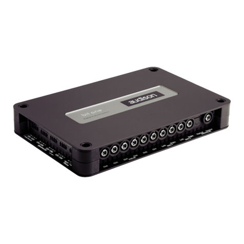
Bit One is a signal digital processor essential to maximize the acoustic performance of your Car Audio system.
It consists of a 32 bit DSP processor and 24 bit AD and DA converters.
What makes it a unique device is that it provides the ability to de-equalize car factory systems equipped with
integrated audio processor, to enhance and improve any car audio factory system.
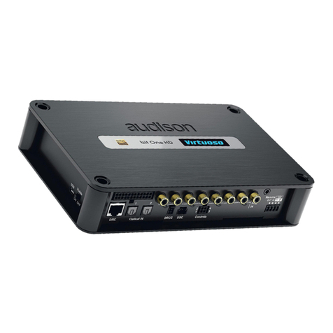
It features 10 PRE Amp Level signal inputs, 8 Speaker Level signal inputs, an optical and electrical S/PDIF digital
input as well as a PHONE IN input allowing the use of cellular phones hands-free kits.
It provides 8 outputs both at a pre-amplified and a digital level.
A 32 band equalizer, an electronic crossover and a digital delay are available for each channel.
To perform the different possible adjustments a connection with a PC is required.
WARNING: a PC provided with Windows XP or Vista operating system, 1GHz minimum
processor speed and 1GB RAM minimum memory. is required to
install the software and setup the Bit One,
ADVANCED MANUAL / Bit One
3

ADVANCED MANUAL / Bit One
4
INSTALLATION
External dimensions
How to secure the product
Mounting dimensions
(provided)
ADVANCED MANUAL / Bit One
4
225 mm
150 mm
201 mm
126 mm
4.2 x 38 mm
32.3 mm

ADVANCED MANUAL / Bit One
5
1 • MASTER PRE IN (low-level inputs)
Ch1 - Ch2 - Ch3 - Ch4 - Ch5 - Ch6
Connect here the RCA cables coming from the main analog signal source.
If these inputs are used, the MASTER SPEAKER IN inputs can not be used.
2 • AUXILIARY PRE IN (low-level inputs)
AUX1 - AUX2
Connect here the RCA cables coming from additional analog signal sources.
3 • DIGITAL IN (digital inputs)
Optical - Coaxial (S/PDIF standard, Max 48 kHz / 24 bit)
Connect here the specific cables coming from signal sources with digital output.
4 • MASTER SPEAKER IN (hi-level input)
Ch1 - Ch2 - Ch3 - Ch4 - Ch5 - Ch6 - Ch7 - Ch8
Connect here the specific cables coming from the power output of the main signal source.
If these inputs are used, the MASTER PRE IN inputs can not be used.
Ch1 features AUTO TURN ON (ART)
5 • HANDSFREE IN (high-level input)
Phone: Signal (+/-) , Mute.
Connect here the specific cables coming from the used handsfree car kit.
INPUT / OUTPUT CONNECTION PANELS - DESCRIPTION
INPUT SIGNALS
negative pole (ground)
positive pole
ADVANCED MANUAL / Bit One
5
4 5
3

ADVANCED MANUAL / Bit One
6
OUTPUT SIGNALS
1 • PRE OUT (low-level analog signal)
Ch1 - Ch2 - Ch3 - Ch4 - Ch5 - Ch6 - Ch7 - Ch8
Connect here the RCA cables going to the system amplifiers.
2 • AD Link - OUT (digital signal)
S/PDIF standard digital signal (Ch1÷Ch8) to connect amplifiers provided with appropriate AD Link input.
3 • AC Link 1 - 2 (REMOTE CONTROLS)
DRC: Connection plug for the remote control panel of the processor functions and the devices connected to the
AMPS bus.
AMPS: Connection bus to control the amplifiers provided with AC Link connection.
REMOTE CONTROLS INPUTS / OUTPUTS
4 • REMOTE IN-OUT
IN: for the processor remote turn-on through one or multiple signal sources, featuring Rem Out control.
OUT: output for the remote turn-on of the other devices/amplifiers connected to the processor.
The REMOTE OUT output current capability is 20 mA.
WARNING: the Bit One must be switched on before the amplifiers connected. It’s necessary to connect the sources
Remote Out to the Bit One Remote In and then the Bit One Remote Out to the Remote In of the other devices/
amplifiers connected to the processor.
5 • KEY SWITCH
MEM: it stores the processor status at shutdown (optional)
ON - OFF: it turns the processor on/off when the car ignition key is turned on/off (optional).
6 • POWER (power supply connection)
- 12V + : Positive and negative connection terminal for car 12 V power supply.
WARNING: make sure the connection polarity is as indicated on the terminals. A mis-connection may result in
damage to the processor.
7 • USB
USB (B) connection plug, to connect the processor to a PC and manage its functions through the Bit One software.
INPUT / OUTPUT CONNECTION PANELS - DESCRIPTION
ADVANCED MANUAL / Bit One
6
6 754
AMPSDRC
1 - AC Li nk - 2
123

ADVANCED MANUAL / Bit One
7
CONNECTIONS
POWER SUPPLY AND REMOTE TURN-ON
PERSONAL COMPUTER and DIGITAL REMOTE CONTROL (DRC)
HOW TO TURN THE BIT ONE ON / OFF ONCE INSTALLED
1. Push the DRC main control switch (to turn on). Keep the DRC main control knob pressed (to shut down). In this
case no other connections (Remote In / KEY SWITCH) are required.
2. Connecting one of the Remote In plugs using a Remote signal coming from one source (the KEY SWITCH
connection is not required).
3. Through the KEY SWITCH ON OFF. Every time you turn on / off the car ignition key, the Bit One will turn on / off. If
this control is used, KEY SWITCH MEM can not be used.
4. Through the KEY SWITCH MEM. Every time you turn on / off the car ignition key, the Bit One will recall how it was
shut down the previous time; if the processor was shut down through the DRC it will turn on again only through the
DRC. If the processor was shut down with the KEY SWITCH MEM, it will automatically turn on again when you turn on
the car ignition key. If you use the KEY SWITCH MEM, the KEY SWITCH ON OFF can not be used.
5. Through the SPEAKER IN CH1 ART. The AUTO TURN ON (ART) activates by connecting the amplified head unit
output to the SPEAKER IN CH1 input channel.
ADVANCED MANUAL / Bit One
7
1
3
4
Fuse Holder
Not provided
Ground Battery Ground
2
L: 7 mm (5/16”)
MAX: 16 AWG
DRC IN
USB cable
(provided)
DRC / AC Link cable
(provided)
TO THE SYSTEM’S AMPLIFIER
AC Link PROVIDED

ADVANCED MANUAL / Bit One
8
CONNECTIONS:
LOW-LEVEL AND DIGITAL INPUT SIGNALS
PRE IN - AUX 1
DIGITAL OPTICAL
PRE IN - AUDIO CAR THEATRE
PRE IN - AUX 2
DIGITAL COAXIAL
PRE IN - STEREO
WARNING: the digital input accepts up to 48 kHz / 24
bit stereo PCM signals. So it can’t reproduce DOLBY
DIGITAL multi-channel signals coming from audio/
video sources (such as for instance the audio of a
movie in a DVD).
ADVANCED MANUAL / Bit One
8
Pre Out
Source
L R
Multi Channel Source
Analog Preamplified Signal
SUB
CENTER
REAR FRONT
Auxiliary Stereo
Preamplifier Source
Auxiliary Stereo
Preamplifier
Source
Signal: PCM Max 48 kHz / 24 bit
Stereo Source
Digital Signal
Stereo Source
Digital Signal
75 ohm coax cable
Signal: PCM Max 48 kHz / 24 bit
BIT ONE
Bottom Side

ADVANCED MANUAL / Bit One
9
CONNECTIONS:
HIGH-LEVEL INPUT SIGNALS
HIGH LEVEL STEREO FRONT + REAR
HIGH LEVEL MULTICHANNEL
HANDSFREE TELEPHONE KIT CONNECTION
ADVANCED MANUAL / Bit One
9
CH1: Auto Turn On System
Front Rear
Amplified Source
MAX:
8 amplified
channels
Original amplified source
CH1: Auto Turn On System
Phone signal
mute
BIT ONE
Left Side

ADVANCED MANUAL / Bit One
10
CONNECTIONS:
OUTPUT SIGNALS
OUTPUT TO AN AMPLIFIERS SYSTEM PROVIDED WITH AD
LINK AND AC LINK CONNECTION (THESIS TH)
OUTPUT TO A PRE PROVIDED AMPLIFIERS SYSTEM
See section “HOW TO CONNECT
THE BIT ONE TO THE pc” point 13
See section “HOW TO CONNECT
THE BIT ONE TO THE pc” point 13
See section “HOW TO CONNECT
THE BIT ONE TO THE pc” point 13
OUTPUT TO AN AMPLIFIERS SYSTEM PROVIDED WITH AD
LINK CONNECTIONS (THESIS TH) AMPLIFIERS SYSTEM
PROVIDED WITH PRE INPUT
ADVANCED MANUAL / Bit One
10
AMPSDRC
1 - AC Lin k - 2
DRC AC Link
Function Control
AD Link
Digital Signal
Other
TH amplifier TH
amplifier
TH
amplifier
TH
amplifier
AMPSDRC
1 - AC L in k - 2
Other
amplifier
DRC
BIT ONE
Top Side
DRC AC Link
Function Control
TH
amplifier
TH
amplifier
Other
TH amplifier
Other
amplifier
AD Link

ADVANCED MANUAL / Bit One
11
BIT ONE SOFTWARE AND DRIVERS - QUICK INSTALLATION GUIDE
1. Insert the “Bit One Setup CD” CD-ROM into the PC CD-player you want to use.
2. Install the Bit One control software launching the file “setup.exe” that is in the supplied CD.
3. Follow and complete the installation procedure.
4. Leave the CD-ROM inside the drive.
5. Turn the Bit One on.
6. Connect the USB cable coming from its appropriate plug on the Bit One to a USB plug available
on the PC.
WARNING: When connecting a PC laptop via a USB cable to the Bit One being the device turned on, the laptop has
to work with its own battery, keeping it disconnected from the mains adapter (external power supply). Once the
connection between the PC laptop and the Bit One is established, you can immediately connect the computer, if
necessary, through the mains adapter.
7. XP:The PC will recognise the Bit One interface and will ask you to install the driver:
Vista: Click on “Locate and install driver software (recommended)”
8. XP: select “No, not this time” and click on “Next”
Vista: click on “Don’t search online”
9. Check if the Bit One Setup CD is inside the CD-ROM drive
XP: select “Install software automatically” then click on “Next”;
Vista: click on “Next”
ADVANCED MANUAL / Bit One
11

ADVANCED MANUAL / Bit One
12
10. The following window regarding the driver certification warning will show up.
XP: click on “Continue Anyway”;
Vista: click on “Install driver software”;
11. The system will install the ACLink interface drivers:
12. If the procedure was successfully completed, the system will notify you that the driver installation has been completed.
XP: click on “Finish”;
Vista: click on “Close”
13. The system will now recognise the virtual serial port connected to the Bit One and will ask you to install the driver:
ADVANCED MANUAL / Bit One
12

ADVANCED MANUAL / Bit One
13
14. XP: select “No, not this time” and click on “Next”;
Vista: click on “Don’t search online”
15. Check if the Bit One Setup CD is inside the CD-ROM drive.
XP: select “Install software automatically” then click on “Next”;
Vista: click on “Next”;
16. The following window regarding the driver certification warning will show up.
XP: click on “Continue Anyway”;
Vista: click on “Install driver software”;
17. The system will install the ACLink drivers:
ADVANCED MANUAL / Bit One
13

ADVANCED MANUAL / Bit One
14
18. If the procedure was successfully completed, the system will notify you that the driver installation has been completed.
XP: click on “Finish”;
Vista: click on “Close”;
19. The installation of the Bit One software and driver is now completed.
TROUBLESHOOTING SECTION
- If you receive error messages when installing the software or the drivers, check if the user account you are using on
your PC has admin privileges.
- If the PC shows an error message regarding the connection with the Bit One (for example “Bit One device not
found”), check the following points:
•
If the DRC display shows the message “audison: vol bal fad sub”:
There should be a fault in the PC, for instance due to a wrong installation of the software or the drivers, or due to
undetectable problems, on an operating system or hardware level.
•
If the DRC display shows the message “PC control - DRC is disabled”:
In this case the PC is correctly initializing the AC Link bus but the fault is in the interfacing with the PC. Exit the
program on the PC, turn the Bit One off then on again, then try reconnecting.
If after turning on the Bit One again one of the above messages appears, you may need to perform the AC Link drivers
installation again.
You may be required to uninstall and reinstall the drivers also if other applications overwriting, even partly, the AC Link
drivers have been installed.
ADVANCED MANUAL / Bit One
14

ADVANCED MANUAL / Bit One
15
BIT ONE SOFTWARE AND DRIVERS UNINSTALLATION- QUICK UNINSTALL GUIDE
Software Uninstall
Automatic procedure
-
To uninstall the Bit One PC software you can use the link listed on the menu:
Start / All Programs / bit one 1.5 / uninstall
Manual procedure
-
To uninstall the Bit One PC software you can also follow the standard procedure:
Start / Control Panel / Applications Installation / bit one 1.5 / uninstall
How to uninstall the drivers with Windows XP
1.
DO NOT turn the Bit One off and DO NOT disconnect the USB plug;
2. Open Control Panel and click on System Properties;
3. Select the Hardware folder and click on Device Manager;
4.
Select Ports (COM & LPT), then
right-click on Audison AC Link Port
(COM X) and select Uninstall;
5.
Click on OK when you are asked to
confirm the device uninstall;
8.
Disconnect the USB plug, turn off the Bit One then turn it on again and
connect again the USB plug and one available plug to the PC;
9.
Repeat the installation procedure, see page 11.
6.
Select USB Controllers (Universal Serial Bus controllers) then right-click on
Audison AC Link Interface and select Uninstall;
7.
Click on OK when you are asked to confirm the device uninstall;
ADVANCED MANUAL / Bit One
15

ADVANCED MANUAL / Bit One
16
BIT ONE SOFTWARE AND DRIVERS - QUICK UNINSTALL GUIDE
How to uninstall the drivers with Windows Vista
1.
DO NOT turn the Bit One off and DO NOT disconnect
the USB plug;
2.
Open Control Panel and click on Hardware and Sound;
8.
Disconnect the USB plug, turn off the Bit One then
turn it on again and connect again the USB plug and
one available plug to the PC;
9.
Repeat the installation procedure, see page 11
.
6.
Select USB Controllers (Universal Serial Bus controllers)
then right-click on Audison AC Link Interface and
select Uninstall
;
7.
A window asking you to confirm the device uninstall
will appear; select “Delete the driver software for
this device” and click on OK;
3.
Click on Device Manager;
5.
A window asking you to confirm the device uninstall will appear;
select “Delete the driver software for this device” and click on OK;
4.
Select Ports (COM & LPT),
then right-click on Audison
AC Link Port (COM X) and
select Uninstall;
ADVANCED MANUAL / Bit One
16

ADVANCED MANUAL / Bit One
17
HOW TO CONNECT THE BIT ONE TO THE PC
To adjust the Bit One functions the software is required. The processor needs to be connected to the PC and turned
on. After installing the software, start it by clicking on the icon shown on your desktop.
The first screenshot showing up is the start up page where you need to choose among:
- OFFLINE mode, Bit One not connected;
- TARGET mode, Bit One connected;
- RESCUE mode, Bit One connected for Update/Rescue (see page 37).
To select the start mode select the corresponding entry on the drop down menu, then press ENTER or double click
on the Bit One image.
OFFLINE MODE
In this case even if the Bit One processor is connected to the PC, it does not interact with the software.
The OFFLINE mode can be used to work on the software without connecting the Bit One to the PC, to get familiar with the
processor multiple functions. For more information on the specific functions, see the following pages on this Manual.
The software is pre-set to start with a 3-way + stereo Sub active multi-amplified system.
To set a new “virtual” system, and so to change the inputs and select the outputs, you need to select the function I/O
Configuration Wizard in the “Config” window of the software main menu. (See point n. 4 of the TARGET mode below).
Here is how the Bit One software appears when it is started up in OFFLINE mode.
ADVANCED MANUAL / Bit One
17

ADVANCED MANUAL / Bit One
18
1. The software performs a scan of the PC port looking
for the Bit One; this operation won’t repeat again, unless
the installation settings of the PC hardware change; this
screenshot will show also if you select the TARGET mode
with the Bit One shut down.
2. Once the processor has been detected by the system,
the software will store the connection previously selected
and won’t perform that search on the next turn-on’s. (even
if on each turn-on a different USB port is selected).
POSSIBLE ERROR MESSAGE
3. Bit One NOT found
For some reason the processor is not recognised as
connected to the PC.
Press CANCEL to start up the OFFLINE mode.
TARGET MODE
In this case the Bit One processor has to be connected to the PC and turned on, otherwise the software won’t even
show the TARGET entry as selectable on the start up window.
At this point you need to have in mind the system you want to realize beforehand, since from this moment if you want
to change any of the settings you will have to go through the guided procedure all over again.
More specifically the guided procedure will ask for:
- Which main inputs you want to use (high or low level). Once you select your choice, auxiliary low level or digital
sources can anyway be added. The guided procedure changes according to the selected choice.
- Which auxiliary inputs will be used (ex. : AUX1 or DIGITAL IN or PHONE etc. ).
- Which kind of signals will be allocated to the different inputs (ex. : Front Left or Center or Subwoofer etc. ).
- Which speakers you are using for your system (ex. : 3-way Front or stereo Sub or 2-way Rear etc. ).
- If the system features passive crossovers managing speaker groups (ex. : 3-way system with active mid-low).
- If the system features any speaker connected through the AC Link
The procedure starts automatically.
4. Guided procedure to set the desired car audio system.
Press NEXT to go on with the setting.
Press CANCEL to exit the program..
FIRST START-UP IN TARGET MODE OF THE BIT ONE SOFTWARE
ADVANCED MANUAL / Bit One
18
1
2
3
4

ADVANCED MANUAL / Bit One
19
5. Inputs selection
- Select the main inputs (MASTER) type (Low Level or High
Level) used. To change this setting afterwards, you will
have to go through this guided procedure all over again;
- Among the available auxiliary inputs (AUX1 - AUX2 - S/P
DIF - OPTICAL – PHONE) pick those that wil be used.
You can change this setting afterwards by selecting
“Config / External Source” on the software main menu.
Press BACK to go back to the previous step.
Press NEXT to go ahead with the set-up procedure.
Press CANCEL to exit the program.
MASTER LOW-LEVEL INPUTS SELECTION
6. How to set up low-level inputs
An identifying name corresponding to the signal coming
from the source can be assigned to any of the processor
input channels (Ch1÷Ch6). The available names are:
Front Left, Front Right, Rear Left, Rear Right, Center,
Subwoofer. The Bit One will use these names to assign
the corresponding signal to the respective output.
Press BACK to go back to the previous step.
Press NEXT to go ahead with the set-up procedure.
Press CANCEL to exit the program.
7. How to calibrate the MASTER inputs level
Follow the instructions listed below:
- Insert into the CD player of your head unit the
“Installation CD” provided;
- Play track 1 (press Play);
- Set all tone controls to zero (0);
- Set balance and fader to center (0);
- Adjust the head unit volume to the maximum undistorted
output level.
Press BACK to go back to the previous step.
Press NEXT to go ahead with the set-up procedure.
Press CANCEL to exit the program.
Remark: calibration is absolutely required to adapt the
Bit One inputs sensitivity to the signal coming from the
source.
8. Automatic calibration
Through a real-time progress bar and specific messages
the software shows how the procedure is being executed.
Once the procedure is completed, the window will show
the message “Press Next to Continue”.
Press BACK to go back to the previous step.
Press NEXT to go ahead with the set-up procedure.
Press CANCEL to exit the program.
ADVANCED MANUAL / Bit One
19
6
7
5
8

ADVANCED MANUAL / Bit One
20
POSSIBLE ERROR MESSAGE
9. “Input level too low“
Should the procedure get interrupted during the
calibration with the above message showing up, check
if the signal or its level is present on the indicated
corresponding channel.
Press CANCEL to log out the program.
Press BACK to go back to the inputs set-up.
10. How to select the speakers available in the
system
Speakers can be selected just by clicking on it.
If the left tweeter, left midrange or left woofer are selected,
the software provides the ability to automatically activate
also the right tweeter, right midrange or right woofer.
Once the software has been started up, this choice will
affect the dedicated crossover type. Ex.: if on the rear
system only the woofers were activated, the software
will show exclusively a low-pass or band-pass filter as
available.
If you want to use a coaxial system as rear channel,
both tweeter and woofer need to be selected and after
that (see point n. 11) you need to enter that a passive
crossover connecting one to the other is present in the
system, so the software will show a high-pass filter as
available.
Press BACK to go back to the previous step.
Press NEXT to go ahead with the set-up procedure.
Press CANCEL to exit the program.
From this point on follows a simulation of a system made
up of:
- 3-way Front/ - 2-way Rear / - 2-way centerl / - mono Sub.
The Bit One features 8 output channels. To multi-amplify
each single speaker of the system 13 output channels
would be required. In that case the software would
automatically signal the limit.
11. How to select passive crossovers for speaker
groups
While carrying out the configuration of your system,
you can also set the presence of passive crossovers
managing speaker functional groups in complex systems
Ex.: The 3-way Front can be managed as:
- multi-amplified (6 output channels would be required);
- passive mid-high speakers + separately amplified
woofer (4 output channels would be required);
- 3-way passive (2 output channels would be required).
While performing the set-up, the software will
automatically notify the return within the 8 output channel
limit, the warning message will then disappear and the
NEXT button will appear.
Press BACK to go back to the previous step.
Press NEXT to go ahead with the set-up procedure.
Press CANCEL to exit the program.
Here is how the system speakers selection is
shown by the Bit One software
ADVANCED MANUAL / Bit One
20
9
10
11
Other manuals for bit one
3
Table of contents
Other Audison Signal Processor manuals

