- MANUAL HRC70 HEAT PUMPS 17 20 25 KW - V3
14
The rules and regulations in the country of
installation MUST be respected (standard
C15-100).
• The electrical lines for general power supply to the
circuits must be made in compliance with your
country’s current rules and regulations (standard
C15-100).
• Standard C15-100 determines the cable section to
be used based on acceptable currents.
• Standard C15-100 determines the cable section to
be used based on the following elements :
- Nature of the conductor :
. type of insulation, number of strands, etc...
- Installation mode :
. inuence of conductor and cable groups
. ambient temperature
. tightly or non-tightly installed
. length of cables, etc...
3.4 - Connecting to the power supply
Ensure that the power supply is sucient to supply both the Heat
Pump and the electrical back-up if necessary, taking into account
any other domestic usage of electricity.
Connection to the power supply for each appliance must be done
by a qualied professional with the mains power switched o.
• During transport, the electrical connections
may be subject to accidental loosening.
• To eliminate any risk of abnormal heating, it is
necessary to ensure the placement of the faston
type electrical connections are secure and tighten
the screw connections.
See§ «Spare parts - electrical boxes»
Each appliance is delivered from the factory completely pre-wired.
However, it is necessary to connect the following elements to the
relevant terminals:
• The electrical supply of the power circuit for each appliance
separately : the Heat Pump and the Pilot.
•The dierent temperature sensors, thermostats, and load shedding
device on the Pilot.
• The 2-core sheathed connecting cable (10m length supplied)
between the Heat Pump and the Pilot.
Under no circumstances will the manufacturer be held liable for
any problems which may arise due to improper installation and/or
choice of power supply cable.
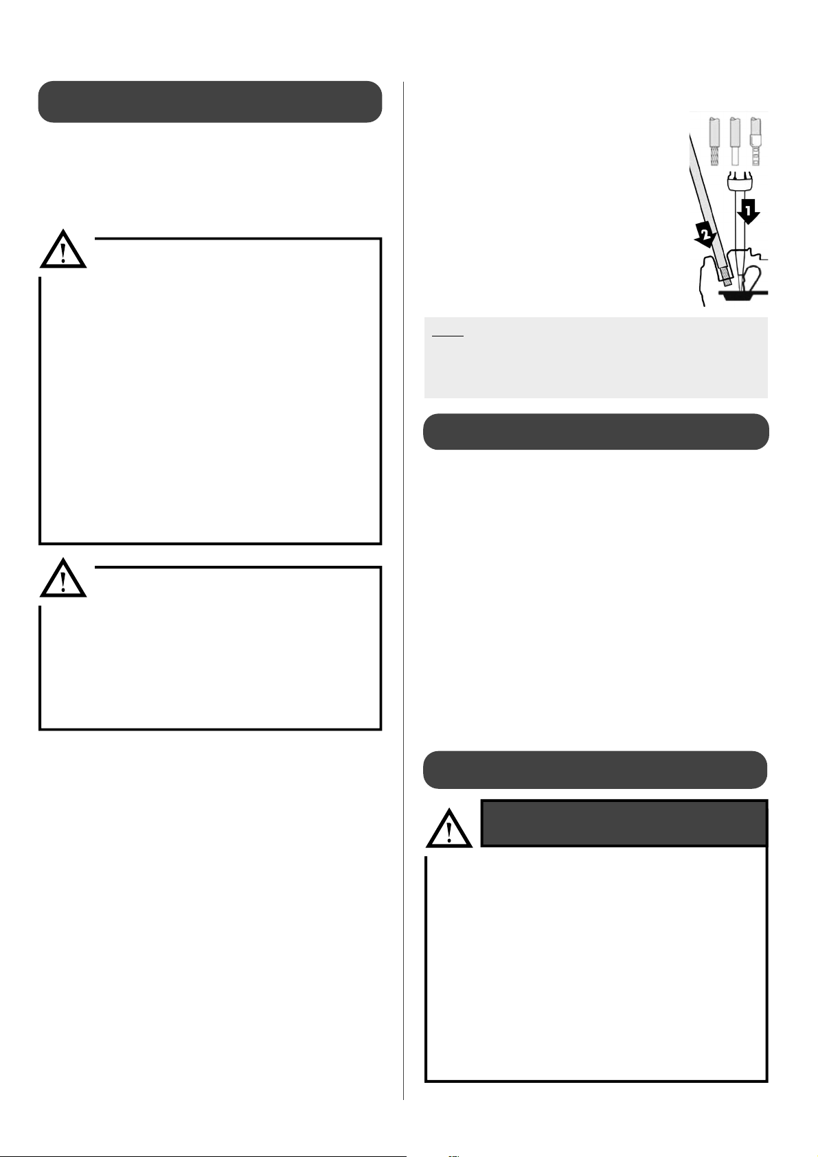
Terminal strips
The terminal strips are spring-loaded «Cage Clamps».
For handling, use the following :
- for2,5mm² control terminals or 4mm² -
6mm² power terminals (tetra), use a 3,5 x
0,5mm at-head screwdriver.
- for 10mm² mains power terminals
(single-phase), use a 5,5 x 0,8mm at-
head screwdriver.
1 : Insert the screwdriver into the ap just above
or below the identication number.
2 : Insert the wire into the «CAGE CLAMP» when
the ap is open.
3 : Remove the screwdriver.
Note : The wires must be stripped to the following lengths:
- for the 2,5mm² control terminals: between 10 and 12mm.
- for the mains power terminals: between 18 and 20mm.
- for the intermediary power terminals: between 11 and 13mm.
3.4.1 - Recommendations for connecting the
system to the power supply
Check :
• The power consumption
• Number and thickness of the power supply
cables
• Fuse or circuit breaker ratings
The power supply must come from an electrical protection and
sectioning device which complies with all current rules and
regulation in eect in the country of use.
This CE-approved unit complies with all the essential requirements
of the following directives:
- Low voltage n°2006/95/CE
- Electromagnetic compatibility n° 2004/108/CE
Ensure that the installation is equipped with a properly sized and
connected grounding cable.
Ensure that the voltage and frequency of the general power supply
ts requirements.
The acceptable variation in voltage is:
230 V -10% to +6%50Hz for single-phase+ Ground models
400 V -10% to +6%50Hz for three-phase+ Neutral + Ground models
3.4.2 - Connecting the HRC70 Heat Pump to the
power supply
- It is the responsibility of the installer and of the
clienttoensurethattheapplianceiscompatible
with the power grid before connecting the
HRC70 Heat Pump (see the electricity provider
information form in the Appendix)
- The power grid impedence value must be less
than the Heat Pump impedance Zmax value (see
§ «Connecting the HRC70 Heat Pump to the
power supply»).
- If the electrical installation standards are not
respected there could be irreversible damages
to the HRC70 Heat Pump which are not covered
by the manufacturer’s warranty.
ELECTRICAL INSTALLATION
RECOMMENDATIONS


