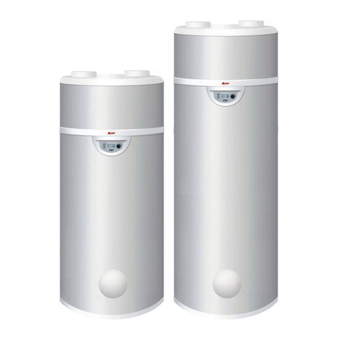
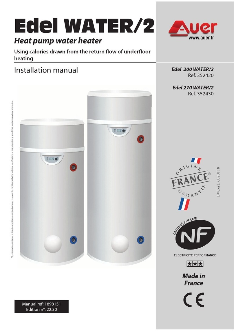
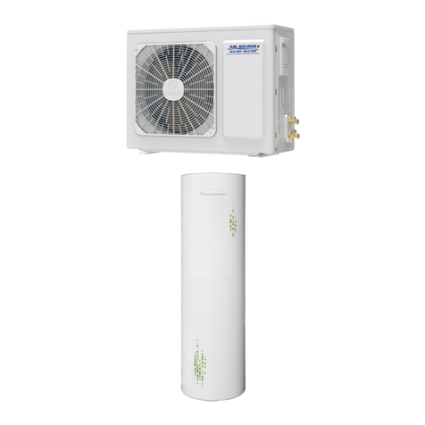
auer Edel AIR Series User manual

Made in
FRANCE
Manual ref. : 1897105
Edition n° 20.029
Installation manual
Edel AIR
Heat pump water heater
using exterior or non-heated ambient air
The information contained in this document is non-contractual. Auer reserves the right to modify the technical specications or characteristics of any of their appliances without prior notice. .
Edel 200 AIR D/2
Ref. 353420
Edel 270 AIR D/2
Ref. 353430
Necessary technical data
-in appendix-

CONTENTS
TABLE DES MATIÈRES
1 SAFETY............................................................ 3
2 RECOMMENDATIONS ..................................... 4
2.1 - Storage............................................................................................................................. 4
2.2 - Transport.........................................................................................................................4
2.3- Contents of packaging................................................................................................ 5
2.4 - Unpacking ......................................................................................................................5
2.5- Symbols used .................................................................................................................5
3 PRESENTATION............................................... 5
3.1 - Dimensions ............................................................................................5
3.1.1 - 200 L Heat pump water heater............................................................................5
3.1.2 - 270 L Heat pump water heater............................................................................5
3.2 - Technical specications and performances ...............................6
4 INSTALLATION................................................ 6
4.1- Placement and positioning...............................................................6
4.1.1- Placement choice ......................................................................................................6
4.1.2- Positioning and anchoring..................................................................................... 6
4.2- Air connection .......................................................................................7
4.2.1 - Without piping...........................................................................................................7
4.2.2 - With piping .................................................................................................................7
4.2.3- Piping accessories .....................................................................................................7
4.3 - Hydraulic connections.......................................................................7
4.4 - Condensates drainage.......................................................................8
4.5 - Electrical connections ........................................................................9
4.5.1 - External control.........................................................................................................9
4.5.1.1 - Peak/o-peak hours contact................................................................9
4.5.1.2 - Controlled ventilation ...........................................................................9
4.5.1.3 - Electricity provider contact ..................................................................9
4.5.1.4 - Connection to the photovoltaic function (PV)............................10
5 SETUP AND USE .......................................... 10
5.1 - Control panel.......................................................................................10
5.2 - Setting the language........................................................................11
5.3 - Setting the time and date...............................................................11
5.4 - Setting the desired water temperature.....................................11
5.4.1 - PV mode inactive.......................................................................................11
5.4.2 - PV mode active...........................................................................................11
5.5 - Holiday/temporary standby mode......................................................12
5.7 - Electric mode (for operation using the electrical back-up)..........12
5.8 - Programming ......................................................................................12
5.6 - BOOST function
(for occasional use and guaranteed comfort)........................................12
5.9 - Installer menu .....................................................................................13
5.9.1 - PV mode.....................................................................................................................13
5.9.2 - Adjusting the operating settings......................................................................13
5.9.2.1 - ANTI-BACT -anti-legionellosis cycle......................................13
5.9.2.2 - fan mode.........................................................................14
5.9.2.3 - T°C. MINI Minimum temperature...................................14
5.9.2.4 - Load shedding -Level authorised during peak hours14
5.9.2.5 - max time Max heating time...............................................14
5.9.3 -Locking the keyboard ............................................................................................14
5.9.4 - Resetting parameters............................................................................................15
5.9.5 - Read data...................................................................................................................15
5.9.6 - Counters (meters)...................................................................................................15
6 MAINTENANCE AND TROUBLESHOOTING16
6.1 - Water circuit / Condensate draining...........................................16
6.3 - Electrical maintenance ....................................................................16
6.2 - Air intake circuit..................................................................................16
6.4 - Troubleshooting.................................................................................17
6.5 - Drainage................................................................................................17
6.6 - Sensor data .........................................................................................17
6.7 - List of spare parts...............................................................................18
6.8 - Error message codes: errors, solutions and operating in case
of error...................................................................................................19
7 WARRANTY ................................................... 21
7.1 - Limitations of warranty....................................................................21
7.1.1 - General information ..............................................................................................21
7.1.2 - Exclusion from warranty ......................................................................................21
7.1.2.1 - Use...............................................................................................................21
7.1.2.2 - Handling....................................................................................................21
7.1.2.3 - Installation site........................................................................................21
7.1.2.4 - Electrical connections ..........................................................................21
7.1.2.5 - Hydraulic connections .........................................................................21
7.1.2.6 - Accessories...............................................................................................21
7.1.2.7 - Maintenance............................................................................................21
8 APPENDICES................................................. 22
8.1 - Performance statistics......................................................................22
8.1.1 - COP development..................................................................................................22
8.1.2 - Heating time.............................................................................................................22
8.2 - Electrical wiring diagram ................................................................23
- installer HEAT PUMP WATER HEATER 200 -270L AIR D/2 -manual -- installer HEAT PUMP WATER HEATER 200 -270L AIR D/2 -manual-
2

Rules and regulations (directives, laws,
and standards)
Once the appliance is installed and switched
on, all decrees, directives, technical rules,
safety measures and standards, must be
respected in their current version in eect.
•This appliance shouldnot beused by: children
under 8 years old; anyone with reduced
physical, sensory or mental capabilities; or
by anyone who has insucient experience
or knowledge of the appliance; unless
they are being supervised by someone
who is responsible for their safety and in
possession of the operating instructions of
the appliance.
• Children should be supervised to ensure that
they do not play with the appliance.
• Cleaning and maintenance of the appliance
should not be undertaken by children
without proper supervision.
The electrical supply must conform to
all applicable regulations in the country
of installation, as well as the NFC 15-100
standards.
A method of disconnection ensuring a
complete cut-off according to Category
III conditions must be installed in the xed
piping to conform to installation regulations.
Protect the appliance with:
• an 8 A all-pole circuit breaker with a
contact opening of at least 3mm.
• a protective 8 A circuit breaker with a
30mA dierential.
If the electrical supply cable is damaged, it
must be replaced by the manufacturer, their
customer service technicians, or by a qualied
professional to prevent any risk of injury or
danger.
If the electrical supply cable is damaged, it
must be replaced by a cable or by a specic
kit available from the manufacturer or their
customer service department.
Water may drain from the discharge pipe of
the pressure limiting device.This pipe should
be kept open to open air.
This appliance respects the 2014-30-UE
directives concerning electromagnetic
compatibility, the 2014-35-UE directive
concerning low voltage, and the 2013-814-UE
concerning eco-design.
1 - SAFETY
Danger of death by electrocution
Touching live electrical wires can cause severe
injury.
• Before undertaking any work on the
appliance, ensure to switch o the power
supply to the appliance.
• Ensure that there is no possibility of the
power supply becoming active again.
Danger of injury or death due to the
absence of, or defective, safety devices.
Absence of safety devices can be dangerous
and may result in burns or other injuries.
Injuries could be caused by pipes bursting
for example.
The information provided in this document
does not represent all of the diagrams
required for a professional installation of the
safety devices.
• Install all required safety devices in the
circuit.
• Inform the user of where the safety devices
are placed, and how they work.
• Follow all relevant national and international
health and safety rules and regulations.
Danger resulting from improper use
Any work carried out by an unqualied person
can result in damage to the installation or in
physical injury.
• Do not perform any maintenance work on
this appliance unless you are a qualified
professional.
Intended use and applicable areas of use
This appliance is intended for use as an
appliance for domestic hot water production.
The intended use of the appliance includes
the following points:
• following the instructions for operating,
installing, and maintaining this appliance
and all other parts and components of the
system.
• ensuring the compliance with all
conditions of inspection and maintenance
which are listed in this manual.
Humidity and water splashes
The appliance should be installed in an area
where it is not exposed to humidity and
without risk of being splashed by water.
Preserving these documents
• This manual and all other relevant documents should be given to
the system user.
The system user should keep these manuals for future reference.
- installer HEAT PUMP WATER HEATER 200 -270L AIR D/2 -manual -- installer HEAT PUMP WATER HEATER 200 -270L AIR D/2 -manual- 3

2.1 - Storage
STORAGE AND INSTALLATION
PRECAUTIONS:
•The appliance must not be stored in an enclosed
space of less than 4m
2without ventilation.
• If the appliance is to be stored in a space with
less than 4m2of surface area (e.g. in a cupboard)
there must be ventilation points at the top and
bottom of this space.
Authorised transport positions :
All other transport positions are prohibited.
2- RECOMMENDATIONS
• Verify that the ventilation openings are not
obstructed.
•Anew pressure-reliefvalve(not included)must
be installed and set to 6 bars on the domestic
cold water supply of the appliance. The use of
a membrane valve is recommended.
•Thisvalvemust conformtoall nationalstandards
in eect.
•The pressure-relief drainage outlet should
be installed in a frost-free place and in a
downward sloping position.
- Maintenance - Troubleshooting -
• Drainage : Turn o the power supply and the
cold water, open the hot water valves and then
set the safety group to the drainage position.
• The pressure-relief valve should be activated
regularlyso astoeliminatelimescale andcheck
for blockages.
•.If the electrical supply cable is damaged, it
must be replaced by the manufacturer, their
customer service technicians, or by a qualied
professional to avoid risk of injury.
• See the § «Dimensions» (page 5) and the §
«Installation» (page 6) ofthismanualtondthe
necessary dimensions for proper installation of
this appliance.
• See the § «Hydraulic connections» (page 7) of
thismanualtondtheminimumandmaximum
water pressures and temperatures.
WARNING
Do not use any methods to accelerate the
defrosting or cleaning process other than
those recommended by the manufacturer.
The appliance must be stored in a room which
does not contain a perpetual ame or other
source of ignition (for example: open ame,
gas powered appliances or electric radiators
in use).
Do not pierce or burn.
Warning: refrigerant uids may be odourless.
The appliance must be installed, used, and
stored in a room larger than 4m².
The appliance can only function when filled
with water. Never turn on the appliance if the
tank has not been properly filled with water
and completely purged of air.
2.2 - Transport
Admissible transport and storage temperatures of the heat pump
water heater are between -20oC and +60oC.
Transporting the appliance in a
horizontal position may lead to
irreparable damage to the components of the
Heat Pump.
All other transport positions are
PROHIBITED.
It is preferable to transport the heat pump water heater in its original
packaging to protect the appliance.
Non-authorised transport positions :
- installer HEAT PUMP WATER HEATER 200 -270L AIR D/2 -manual -- installer HEAT PUMP WATER HEATER 200 -270L AIR D/2 -manual-
4

3.1 - Dimensions
Domestic cold water inlet
(DCW) M3/4G
Domestic cold water inlet
(DCW) M3/4G
3 - PRESENTATION
• 1 heat pump water heater
• 1 doumentation packet containing 1 installation and user
manual, and 1 warranty form.
2.3- Contents of packaging
2.5- Symbols used
Consult the installation
manual before all work
on the product: handling,
installation, use and
maintenance.
Contains controlled
substances, do not dispose
of in the garbage. In case of
disposal, please respect the
regulations for the recovery
of electrical and electronic
equipment.
Caution : contains a
ammable refrigerant uid.
Please make sure to
respect the installation and
handling precautions.
Keep the transport bag out of the reach of
children (risk of suocation).
If tipped, the centre of gravity will shift
towards the top: handle with care.
• Remove plastic cover and cardboard packaging.
• Remove corner protection pieces, ensuring that all nails and
staples are taken out and disposed of.
• Remove protective lm from all parts of the appliance and from
the bag of accessories which you will nd in the transport bag.
• Without tilting the appliance, use the appropriate tool to remove
the screw from underneath the wooden pallet.
2.4 - Unpacking
Do not drop or lower suddenly
Risk of tipping
Once the heat pump water heater is
installed in its denitive position, it
is imperative to wait 15 minutes before it is
turned on.
3.1.1 - 200 L Heat pump water heater
3.1.2 - 270 L Heat pump water heater
- installer HEAT PUMP WATER HEATER 200 -270L AIR D/2 -manual -- installer HEAT PUMP WATER HEATER 200 -270L AIR D/2 -manual- 5

4.1.2- Positioning and anchoring
• To ensure the proper functioning of the heat pump water heater
and to facilitate maintenance work, a space must be left free
around the appliance, as well as a minimum ceiling height so
that the hood can be removed.
• It is PROHIBITED to install the appliance:
- Outside.
- In rooms exposed to frost, where the temperature is less than
7°C, including when the appliance is operating.
- In humid rooms which have signicant steam or vapour
emissions (for example, a bathroom).
- In rooms where there is any risk of explosion due to gas,
pollution or dust.
•Avoid placing the appliance close to bedrooms to minimise
noise pollution.
• Do not install the air intake nozzle near a vapour exhaust
(minimum distance of 0,6m).
3.2 - Technical specications and
performances
4.1- Placement and positioning
• It is PROHIBITED :
- To let the appliance operate using air intake which contains
solvents or explosive materials.
- To use air intake which contains grease, dust or aerosol particles.
- To connect vented exhaust hoods to the ventilation system.
-To use air intake containing combustion materials from a boiler.
4 - INSTALLATION
INSTALLATION PRECAUTIONS :
• The appliance must not be installed near a
perpetual ame or other source of ignition.
• The appliance must be installed in such a way so
as to avoid mechanical damage to the appliance.
4.1.1- Placement choice
Heat pump performance
Nominal volume L 200 270
Max. input power W 1900 1900
Air temperature range OC 7 to +35 7 to +35
DHW* temperature with heat
pump
OC 30 to 60 30 to 60
Max. heat pump power
consumption W 700 700
Air ow rate m3/h 320 to 400 320 to 400
Sound pressure level at 1m** dB(A) 37/40 37/40
Refrigerant -/kg R290 /0.15 R290 /0.15
Global warming potential kg 0.45kg CO2
equivalent
0.45kg CO2
equivalent
Type of air connection Exterior or
ambient air Exterior or
ambient air
Normative Data (EN 16147)
Draw cycle L L
COP* outdoor air +7
oC) 3.19 3.14
Reserve capacity W 23 25
Hot water reference
temperature
O
C 54.2 55.8
Heating time 7H04 10H15
Energy class - A+ A+
Seasonal energy eciency % 132 130
Vmax L 247.4 349.3
V40 td L 614 650.4
COP* (ambient air +15oC) 3.37 3.47
Dimensions and connections
Dimensions mm Ø630 x H 1460 Ø630xH1780
Weight when empty kg 56.5 63
Air connection diameter
(intake / exhaust)
mm 160 160
Max. length for air ducts m Flexible tube: 6m
Rigid pipe: 12m
(intake + exhaust)
Connection diameter for
DCW* and DHW* inches M 3/4" M 3/4"
Electrical power supply V-Hz-A 230V50Hz-8A 230V50Hz-8A
Protection rating - IPX4 IPX4
D-curve circuit breaker A 8 8
Tank
Materials / protection Stainless
steel
Stainless
steel
Maximum service pressure MPa0.6 6 bars) 0.6 6 bars)
Max. condensates ow rate L/h 0.3 0.3
Built-in electrical back-up
power (85-C safety setting) W 1200 1200
Max. temp with electrical
back-up CO65 65
- installer HEAT PUMP WATER HEATER 200 -270L AIR D/2 -manual -- installer HEAT PUMP WATER HEATER 200 -270L AIR D/2 -manual-
6
EDEL AIR
200L D/2 EDEL AIR
270L D/2

• The oor must be able to support the weight of the heat pump
water heater (weight of the heat pump water heater lled with
water 200 L/ 270 L= 260 kg / 335 kg).
If installed without piping, the appliance must be installed in non-
heated premises (of at least 20m2and away from neighboring heated
rooms.
•If the space available under the ceiling is less than 60cm in height
above the water heater, it is recommended to install an elbow at the
air outlet and direct it towards the back or the sides.
•The heat pump water heater enables heat to be recovered from
the oor of non-heated, partially underground premises such as a
workshop or garage.
• The heat pump water heater allows the dehumidifying and cooling
of rooms such as utility rooms or cellars.
4.2- Air connection
4.2.1 - Without piping
Partial piping
Exterior air Heated room
The heat pump can operate over a large air temperature range (from
-7°C to +35°C). The appliance extracts calories from exterior air. Partial
piping (using only 1 pipe) onto exterior air should be avoided as in
the winter it can cause the room to become signicantly colder.
4.2.2 - With piping
piping at the back piping on the right piping on the left
The heat pump water heater must be connected using
insulated air ducts with an interior diameter of 160mm.
90° Ø160 mm PVC elbows allow you to rotate the position of the
pipes connected to the appliance through 360o.
Total maximum length Ø160 :
• 6 m of exible hose
• 12 m of semi rigid piping
1 elbow= 1m
Rep. Description
Semi-rigid pipe Ø160mm - lg 2m
Insulated 90° elbow Ø160mm
Collars for attaching to wall (set of 2)
Connectors for insulated pipes (set
of 2)
Horizontal terminal for insulated pipe
Piping accessories are available to order and are designed for a
simple and ecient heat pump water heater connection.
The pipes (Ref. 730011) and the foam elbows (Ref. 730012), are
semi-rigid, light and thermally insulated.
They are assembled using an assembly connector. (Ref.730014).
If over 1m long, the pipes must be anchored to the wall using a collar.
(Ref. 730013).
The stainless steel horizontal terminal (Ref. 730015), is equipped
with a protective grill.
4.2.3- Piping accessories
4.3 - Hydraulic connections
• A new pressure-relief valve (not included) must be installed and
set to 6 bars on the domestic cold water supply of the appliance.
We would recommend a membrane valve.
The membrane valve system must conform to national and
domestic standards and regulations in eect.
• The pressure-relief valve should be installed as close as possible
to the appliance’s cold water inlet and the water ow should
never be hampered by any accessory (valve, pressure-
reducer, etc...)
• The pressure-relief valve drainage outlet must be installed in a
frost-free place, in a downward-sloping position.
• The pressure-relief valve drainage outlet should be sized
according to building regulations and must never be obstructed.
It should be connected to a vertical draining pipe, using a funnel
which allows an open space of at least 20mm and which is at
least equal in diameter to the appliance’s piping connection.
• If the pressure of the domestic cold water supply is higher than 5
bars, a pressure-reducer should be installed above the pressure-
relief valve near the starting point of the installation (a pressure
of 4-5 bars is recommended).
• It is advised to t a shut-o valve above the pressure-relief valve.
• For installations equipped with:
- piping of a small diameter
- ceramic plate valves
A domestic water expansion vessel, or anti-hammer valves
which are adapted to the installation should be installed as close
as possible to the shut-o valve.
• The following materials should be used for the
The vertical position of the heat pump
water heater must be strictly respected.
If not, there is a risk of condensates
leaking and resulting in a water leak at
the base of the appliance.
• Use the anchoring point at the bottom of the tank to x the
appliance to the oor, using the metal tab (pre-assembled under
the foot) and an ØM8 screw which can be then dowelled into
the ground (see Rep.).
- installer HEAT PUMP WATER HEATER 200 -270L AIR D/2 -manual -- installer HEAT PUMP WATER HEATER 200 -270L AIR D/2 -manual- 7

If any of these points have been neglected
or if the water quality did not allow correct
treatment within the legal framework the
warranty will be null and void.
Use of a recirculation pump should be
avoided. Recirculating can cause a lack
of hot water and overconsumption of
energy. If using a recirculation pump, the piping
should be insulated and the pump should be
controlled by a timer or another system which
will prevent domestic hot water from circulating
continuously.
domestic hot water circuit:
- copper
- stainless steel
- brass
- plastic
If the materials used in the domestic hot water
circuit are incompatible, corrosion damage may
occur.
Consequently, the appliance should always be connected to copper
domestic hot water pipes with a cast-iron or steel link, or with
dielectric connections (not supplied) to avoid an iron/copper
galvanic bridge.
• Thoroughly ush the supply line piping before connecting the
appliance to the domestic installation so as not to introduce any
particles, metallic or other, into the appliance.
• Respect the standards in eect in the country of use, notably
hydraulic regulations and pressure safety regulations.
• The appliance must operate with water between 12oF and 30oF.
With particularly hard water (TH>25oF) it is advised to use a water
softener.
• If any of these points have been neglected the warranty will be
null and void (values given are for water at a temperature of
20oC). (See DTU-60-1 for more information).
1. Stop valve
2. Pressure reducing valve
3. Check- valve
4. Insulating dielectric sleeve (not
supplied)
5. Pressurereliefmembrane valve (not
supplied)
7. Run-o siphon
8. Domestic water expansion vessel
9. Thermostatic mixing valve
10. Drainage valve
Flexible condensate
drainage tube
Domestic cold
water (DCW)
Domestic hot
water (DHW)
- The condensates tube should not be directly connected to a
drain. It must lead o into open air in a siphon which has been
added and contains water.
- Do not use a lip seal.
- Do not use an elbow on the exible hose.
4.4 - Condensates drainage
Resistivity <2200 Ωcm or <4500Ωcm
Complete
alkalimetric title
<1.6 meq/l <8OF
CO2<15 mg/l
Calcium (Ca++) <1.6 meq/l <8OF
Sulfates (SO4
--) >2 meq/l <10OF
Chlorides (Cl-) >2 meq/l <10OF
Sulfates and
Chlorides(SO4
--+Cl-)>3 meq/l <15OF
- installer HEAT PUMP WATER HEATER 200 -270L AIR D/2 -manual -- installer HEAT PUMP WATER HEATER 200 -270L AIR D/2 -manual-
8

To access the electrical connections hub:
• Remove the cover and the shell.
• Remove the cover of the appliance by removing the screws which
x the shell onto the lower part of the appliance.
• Remove the black protective cover from the electronics board.
The power supply should comply with all regulations in eect in
the country of installation, as well as the NFC 15-100 standard.
A method of disconnection which ensures total power-cut in
Category III conditions should be installed in xed piping in
compliance with the installation rules.
• an 8A all-pole circuit breaker with a minimum 3mm
contact opening.
• a protective 8A circuit breaker with a 30mA dierential.
If the power supply cable is damaged it must be replaced by the
manufacturer, their customer service technicians, or by a qualied
technician to avoid any risk of injury or danger.
4.5 - Electrical connections
4.5.1 - External control
Only a dry contact, voltage-free, external
connection may be used. Otherwise you
risk damage to the electronics board.
Do not connect the heat pump water
heater to wiring from an older water
heater using the peak/o-peak hours contact.
The heat pump water heater must always be
connected to a power supply.
Peak/o-peak control can be managed through
programming or though an independent cable.
Grounding is obligatory.
Power supply is managed through a 230V single-
phase and grounding cable.
The heat pump water heater can be used to continuously
ventilate a room even if the heating cycle is complete.
To stop the fan from operating, connect a timer on a moisture
sensor. Use the same procedure as for the timer switch, but
connect the 2-wire cable to «Input 2» on the electronics board.
- Switch open = the fan will not operate
- Switch closed = the fan will operate
• Set the regulator to «External control ventilation mode» : fan
mode 3.
4.5.1.2 - Controlled ventilation
4.5.1.1 - Peak/o-peak hours contact
To prevent the electrical back-up from running during peak
hours, connect the dry contact originating from the electricity
counter, to terminal 1.
- Switch open = Back-up not allowed to run
- Switch closed = Back-up allowed to run
By choosing load shedding level 0 or 1 (see § «Load shedding»),
you stop the electrical back-up alone from running (load
shedding =1) or the heat pump and the electrical back-up from
running (load shedding = 0).
• Pass a 0,75mm² 2-wire cable with metal tips through a cable
gland at the back of the appliance and bring the end of the
cable around to the electronics board. The other end of the cable
should be connected to the timer switch.
• Insert the 2-wire cable through a grommet from the electronics
box.
• Connect the 2-wire cable to «Input 1» indicated on the electonics
board, having already removed the existing red bridge.
4.5.1.3 - Electricity provider contact
To program the operation of the heat pump water heater during
peak/o-peak hours, it is not necessary to connect the dry contact
to the electricity counter.
It is possible to program scheduled operating times for the heat
pump water heater or of the electrical back-up from the control
panel (see §3.8 Programming).
It is possible to connect the dry contact from the electricity
counter to the heat pump water heater without programming
from the control panel.
- Switch open = Load shedding
- Switch closed = Normal functioning
The level of load shedding can be chosen from the control panel
of the appliance (see § 5.9.2.4 Load shedding).
By default the electrical resistance does not operate during peak
hours. .
It is not advised to operate the heat
pump water heater during o-peak hours
so as to optimise its functionality.
- installer HEAT PUMP WATER HEATER 200 -270L AIR D/2 -manual -- installer HEAT PUMP WATER HEATER 200 -270L AIR D/2 -manual- 9

4.5.1.4 - Connection to the photovoltaic function (PV)
This function enables the
appliance to operate in auto-
production mode, which
means that it will use the
energy produced by the PV
function to supply the heat
pump as well as the electrical
back-up, and to heat the water
in the tank.
The connection is made
between the energy manager
electrical box (not supplied)
and connectors 1 and 2 on the electronics board.
• Remove the protective casing.
• Remove the black cover from the electronics board.
• Connect the PV function cable to connector 1 on the electronics board.
• If the PV function regulator has two control contacts, connect them to connectors 1 and
2 on the electronics board. See § « Electrical box electrical diagram » in the appendix. .
• Terminal 1: a low level of electrical energy is produced by the PV function.
• Terminal 2: a high level of electrical energy is produced by the PV function.
Energy manager
dry contact
CAUTION: Connectors 1 and 2 are for DRY CONTACTS ONLY. They must NEVER be connected to 230V.
Deterioration risk: the water tank must be
lled before the appliance is switched on
or connected to a power supply.
5.1 - Control panel
5 - SET-UP AND USE
• Leave the appliance unplugged.
• Open the hot water outlet which is located the highest on the
appliance.
• Open the cold water inlet on the pressure-relief valve.
• Fill the tank until water is coming out of the highest outlet.
• Close the hot water outlet.
Before turning the appliance on, ensure that the entire circuit is
watertight.
The heat pump water heater operates primarily with the
heat pump as long as the air intake temperature remains in
the authorised range from -7°C à +35°C. Outside of this range, the
electrical back-up ensures the heating of domestic hot water.
The temperature of the domestic hot water provided by the heat
pump is adjustable up to 60°C.
In the case of high domestic hot water consumption, the heat
pump water heater has a comfort function, t°C mini which
increases the heating capacity when there is less than 1/3 of
the tank’s volume left at over 38°C (see § «t°c mini -minimum
temperature-»). There is also a setting to activate the electrical
back-up if the heating time is too long (see § « max time»).
If more domestic hot water is required from time to time, the heat
pump water heater has a « boost» function (activated by the user)
which ensures that the water heats to the desired temperature
(
for example: 50°C
) quickly with the help of the heat pump and
electrical back-up, This function is deactivated as soon
MENU access
On/off
Clock settings Dial
LCD display
as the required temperature is reached.
From time to time, check that there are no alerts (in case of an
alert, please refer to § «Error messages»).
..... Compressor activated
..... Fan activated
........ Defrosting in progress
........ Electrical back-up
activated
.... Domestic hot water
requested
.... Comfort mode in
progress
....... Eco mode in progress
....... Freeze protection mode
in progress
...... Holiday mode in progress
..... Keyboard locked
......... Settings/parameters
being displayed
.... PV mode activated
123...7.Date
Pictograms:
- installer HEAT PUMP WATER HEATER 200 -270L AIR D/2 -manual -- installer HEAT PUMP WATER HEATER 200 -270L AIR D/2 -manual-
10

5.3 - Setting the time and date
• Press «Clock settings»
5.2 - Setting the language
Choose the language
Enter
LANGUE LANGUAGE
EN
• Press .
• Turn the dial to scroll through the menu options:
• Press to return to main menu.
The language must be selected when the appliance is turned
on for the rst time. Turn the dial to the left and select «English».
Conrm by pressing on the dial. Access to the «LANGUage» menu
is always possible.
5.4 - Setting the desired water
temperature
• Press to return to the main menu.
TEmP. water T°C water
50°C
• Press
• Turn the dial to scroll through the menu options:
The water temperature is adjustable from 30°C to 65°C. Up to 60°C,
the water is heated using only the heat pump. From 60oC to 65°C,
the electrical back-up takes over.
Enter
Set the temperature
• In order to get the best results from your heat pump, it is
recommended that you do not set the water temperature too
high unless necessary. The default temperature is set at 55°C.
5.4.1 - PV mode inactive
Set the month
26/09/11
17: 32
--/09/11
17: 32
26/--/11
17: 32
Set the day
26/09/--
17: 32 Set the year
monday
-- : 32 Set the hour
monday
17: -- Set the minutes
Conrm new settings
• Press
• Turn the dial to scroll through menu options:
When PV mode is activated, the water temperature can be set to
a higher level to favour operation during periods of photovoltaic
production.
5.4.2 - PV mode active
The settings are available according to the following reasoning:
The heat pump heats the water in the
domestic hot water tank to a higher
temperature than the usual hot water
temperature (mode «PV ECO»)
The heat pump and the electrical back-
up heat the water in the domestic hot
water tank to a higher temperature than
the PV ECO mode (mode «PV mAX»)
TEMP ≤T° PV ECO ≤ T° PV MAX ≤65°C
T°PV ECO
60°C
T°PV mAX
65°C
• Press to return to the main menu.
TEmP. water
T °C water
50°C
T°PV ECO
60°C
T°PV mAX
65°C
Set the temperature
Set the temperature
Set the temperature
Enter
- installer HEAT PUMP WATER HEATER 200 -270L AIR D/2 -manual -- installer HEAT PUMP WATER HEATER 200 -270L AIR D/2 -manual- 11

Enter
holidays holi.retur.
8
«holiday» mode switches o automatically when the number
of days set has ended. While in holiday» mode the heat
pump water heater displays «holi. return.» on the
screen, as well as a countdown of the days remaining in standby
mode.
• Press to return to the main menu.
• Press
• Turn the dial to scroll through menu options:
Set the number of days
in standby mode
5.5 - Holiday/temporary standby mode
«holiday» mode puts the appliance on standby while the
frost protection mode remains active. This function can be
programmed to run between 1 and 99 days, and is in eect as
soon as the number of days is conrmed.
ELEC mode
yes
• Press to return to the main menu.
5.7 - Electric mode (for operation using the electrical back-up)
Enter
Electric mode «ELEC mode» uses only the electrical back-up
to heat the water in the heat pump water heater. It provides a
back-up option if for any reason the heat pump is not running
(piping not connected, dusty renovation work being carried out
near the appliance...)
• Press
• Turn the dial to scroll through menu options:
The «boost» function temporarily forces the electrical back-
up and the heat pump to operate at the same time to speed
up heating time during a heating cycle. The electrical back-up
symbol ashes while it activated.
• Press
• Turn the dial to scroll through the menu options:
The «boost» function is automatically deactivated as soon as
the set temperature is reached (end of heating cycle).
• Press to return to the main menu.
boost
yes
5.6 - BOOST function
(for occasional use and guaranteed comfort)
Enter
5.8 - Programming
Programming enables you to dene the periods of time the appliance runs in
«Economy», «Comfort» or «Frost protection» modes. The electrical back-up is not
allowed to run when the appliance is in «Economy» mode.
• Press“Clock settings” and hold down for 3 seconds.
=Copy programming from the previous day
= Copy a standard program or
programming from another day
= Modify existing programming
= See existing programming
frost pt = Frost protection mode
ECO = Heat pump alone running
COmF = Heat pump alone running
+ electrical back-up when needed
Legend
Set end of rst
time slot
Set comfort level for
the rst time slot Set end of second
time slot
new PRoG. 0000-____
00:30h
0000-0630
frost pt
0630-____
06:30h
COPy PROG.
MODIFy PRG.
see PROG.
COPy DIM.
Heating time for the tank
varies according to exterior
temperatures.
Ensure that the operating time of
the appliance is not too limited.
• Press to return to the main menu.
...and so on, up to 7 time periods
per day until 24:00.
monday
day
Select day
- installer HEAT PUMP WATER HEATER 200 -270L AIR D/2 -manual -- installer HEAT PUMP WATER HEATER 200 -270L AIR D/2 -manual-
12

5.9 - Installer menu
It may be necessary to adjust certain temperature settings to
optimise the performance of the heat pump water heater,
depending on how the appliance is installed.
Accessing the installer menu:
• Press
• Turn the dial until the screen displays
«installer menu.»
• Press the «Clock settings» and
«Menu» buttons simultaneously
• Keep both buttons pressed down for 3 sec. until the
screen displays «pv mode»
To adjust the installation settings
settings
To activate photovoltaic operation
MODE PV
To go back to default settings
reset par.
To display temperatures of sensors
and inlets
display
To set the meters running, count
start-ups, etc.
counters
5.9.1 - PV mode
1. If the PV mode regulator is connected to connectors
1 and 2 on the electronics board, PV mode must be
activated.
• The electrical energy which is produced is stored in
the form of hot water. The PV function can be set to
two dierent levels of production.
• PV ECO = the lower level of the photovoltaic energy
production. The heat pump generates a higher
water temperature. The hot water temperature
must be somewhere between the regular hot water
temperature and 60°C (factory setting = 60°C).
• PV MAX = the higher level of photovoltaic electricity
production. The heat pump and electrical back-up generate a
higher water temperature. The hot water temperature must be
somewhere between the eco mode hot water temperature and
65°C (factory setting = 65°C).
2. Turn the dial to set the mode:
- Menu →INST. MENU →PV mode.
3. Select « Yes »
4. Press the dial to conrm.
5. Press Menu.
6. Set the domestic hot water temperature.
7. Turn the dial to select the primary function:
- Menu →INST. MENU → MODE PV →PRIORITY
• Yes: the signals from connectors 1 and 2 take precedence over
eco and frost protection modes.
• No:The eco and frost protection modes take precedence over
the signals from connectors 1 and 2.
N.B.: If PV mode is chosen as the primary function, the domestic
hot water will also be heated during non-selected time periods, e.g.
in holiday mode and outside of the programmed time slots.
If you only wish the domestic hot water to be heated during
authorised time slots, adjust the settings to No.
8. Press the dial to conrm your choice.
• For products which are equipped with an extra thermal heat
exchanger, no boiler request is sent when the heat pump is switched
on. Only the electrical back-up is on, to use the energy produced by
the PV function.
•When fan mode is activated, option 3 may no longer be chosen.
•The load shedding function is not available.
5.9.2 - Adjusting the operating settings
Select setting Modify the
setting
+
settings
Enter
• Press to return to the main menu.
5.9.2.1 - ANTI-BACT -anti-legionellosis cycle
Example :
anti-bact = 8,
temp. water = 60 C
the anti-legionellosis cycle
will run every 8 days at 10pm
Select number of days
ANTI-BACT
no
ANTI-BACT
8 d
Factory setting anti bact = NO
Factory setting temp. water = 60 C
TEMP. water
60 C
Select the temperature
Conrm
Conrm
• If the set temperature for domestic hot water is already 60°C
(see § «Setting the desired water temperature»), there will be no
anti-legionellosis cycle as it is already running continuously.
• Press to return to the main menu.
Parameter Description Unit Time
range Factory
setting
mode pv Activation of
photovoltaic mode yes
no
no
priority Interval of anti-
legionellosis cycles yes
no
yes
Parameter Description Unit Time
range Factory
setting
anti-
bact
Time interval
for anti-
legionellosis
cycle
days 0-99 0
fan
mode
Ventilation
mode 1,2,3 1
toC mini Min. temp for
electrical back-
up
0 or 1 0
shedding Load shedding
level 0,1,2 1
max.
time
Max. heating
time hours No,
auto, 1
to 24
No
- installer HEAT PUMP WATER HEATER 200 -270L AIR D/2 -manual -- installer HEAT PUMP WATER HEATER 200 -270L AIR D/2 -manual- 13

5.9.2.2 - fan mode
Enter
Select the mode
fan mode
fan mode
2
5.9.2.3 - T°C. MINI Minimum temperature
The electrical back-up can be activated at the same time as the
heat pump to prevent the water temperature from going below
a minimum comfort level of 38oC. The electrical back-up will start
up and raise the water temperature to 43oC, and then it will switch
o and the heat pump will complete the heating cycle.
• Press to return to the main menu.
• This function is deactivated by default.
5.9.2.4 - Load shedding -Level authorised
during peak hours
5.9.2.5 - max time Max heating time
Enter
Select mode
T°C. MINI
no
T°C. MINI
yes
Enter
Select the mode
shedding
1
shedding
0
When load shedding is activated you can choose to prevent
certain elements from running (Electrical resistance and
compressor).
• Press to return to the main menu.
If load shedding is switched on:
Mode 0 = No element is allowed to operate
Mode 1 = Only the heat pump is allowed to operate
Mode 2 = The heat pump and back-up are allowed to operate
(neutralising the «peak hours» function)
If the PV function is activated, load shedding cannot be done
through the peak/o-peak hours dry contact. In this case the
timer must be programmed (see § «Programming»).
It is possible to select the length of the desired heating time. The
heat pump water heater can automatically use the electrical back-
up at the same time as the heat pump to speed up the heating
time of the tank.
If you choose MAX time = AUTO, the heating time is limited to a
maximum of 5h during o-peak hours.
• In case of load shedding the «T°C mini» function is not activated.
Factory setting= 1
Mode 1 = Standard mode, automatic ventilation
Mode 2 = Forced ventilation, max speed
Mode 3*= Ventilation activated during water heating periods
and ventilation regulated by an external control
(such as a moisture sensor)
The external control should be connected to connector 2 on the
electronics board in the heat pump water heater. (See appendix
for electrical diagram)
*If PV mode is activated, controlled ventilation (fan moDE 3) is not
available.
• Press to return to the main menu.
Enter
Select time period
between 1 and 24 hours
max time
no
max time
3h
• This function is deactivated by default.
• Press to return to the main menu.
5.9.3 -Locking the keyboard
Enter
Select locking level
locking
locking
no
Permanent and automatic locking
The «locking» menu enables you to create three possible levels of
locking for accessing the menus.
In the «Installer» menu turn the dial to «locking.».
NO = Locking is not activated, but manual
locking is possible by pressing
for 3 seconds.
• If a cycle is interrupted by a period where the back-up is not
allowed to run (electricity provider signal or programmed time
slots) it will relaunch during the next authorised period.
•No anti-legionellosis cycle except when returning from holidays
and after a frost protection period of more than 3 days.
•During the anti-legionellosis cycle the temperature is raised
between 55°C and 70°C.
- installer HEAT PUMP WATER HEATER 200 -270L AIR D/2 -manual -- installer HEAT PUMP WATER HEATER 200 -270L AIR D/2 -manual-
14

5.9.4 - Resetting parameters
Resetting the parameters allows you to go back to the default
settings.
Go to the «Installer», menu and turn the dial to «Reset PAR.».
Enter
Select yes
reset par.
reset par.
yes
5.9.6 - Counters (meters)
The «Counters» menu shows the number of start-ups from the
heat pump and the electrical back-up.
In the «Installer», menu turn the dial to «counters».
COunters
- COunter N°1 :
Number of start-ups from
the heat pump
- COunter N°2 :
Number of start ups from
the electrical back-up
- COunter N°4 :
Accumulated heat pump
running time.
5.9.5 - Read data
The «READ DATA» menu shows you, in real time, the information
given by the sensors.
In the «Installer» menu, turn the dial to «display».
The temperature which is permanently displayed on the screen
is the set temperature and does not necessarily indicate the
temperature of the water immediately available in the tank.
Manual locking from the main screen
Manual locking is possible from the main screen without gaining
access through the «Installer» menu provided that locking
settings are not already in place.
To lock manually, press for 3 seconds.
Press for 3 sec
locking
pro = To lock access to menus with
temporary unlocking (300 seconds)
is possible by pressing for
3 seconds, and then and
buttons for 3 seconds.
Enter
Select yes
500C
unlock.
no
Press for
3 sec
Enter
Select yes
500C
unlock.
no
unlock
yes
Press for
3 sec
Press for 3 sec
AUTO = To lock menu access with temporary unlocking (60
seconds) press for 3 seconds.
•When locking is activated, it is only possible to access unlocking
and to reset the alarm.
Display Description Reference on
electronics
board
water Domestic hot water
temperature in lower part of
tank
Teau
air Temperature of heat pump air
intake Tair
evap Temperature of heat pump
evaporator (expansion valve
outlet)
Tdegiv
mode pv (deactivated) factory settings
shedding O-peak hours switch
(0-on; 1- o)
heures
creuses
fan
contr.
Fan control switch
(0-on; 1- o)
hygrostat
mode pv (activated)
pv eco Contact input 1
(0-open; 1- closed)
1
pv max Contact input 2
(0-open; 1- closed)
2
- installer HEAT PUMP WATER HEATER 200 -270L AIR D/2 -manual -- installer HEAT PUMP WATER HEATER 200 -270L AIR D/2 -manual- 15

Neglecting to clean the circuit board
and other electronic components in a
dusty environment can lead to a risk of
overheating and ignition.
6 - MAINTENANCE AND
TROUBLESHOOTING
In order to maintain eciency and improve durability
it is advised that an annual maintenance check be
carried out by a qualied professional.
• Any work on the heat pump must be
carried out by a qualied professional.
• Observe all health and safety rules !
• Any work on the refrigerant circuit must be
carried out by a qualied professional with a
Category 1 certicate of aptitude.
• It is strictly prohibited to release refrigerant gas
into the atmosphere.
The refrigerant must be collected before any
work is carried out on the circuit.
• Switch o the heat pump water heater before
opening it.
• Wait for the fan to come to a complete stop
before starting work on the appliance.
•Do not get water on any of the electrical parts.
• The pressure limiting device must be operated
regularly to eliminate limescale and to check
for blockages.
• Check the condition of the corrosion-proof
anode at minimum once per year.
6.1 - Water circuit / Condensate
draining
To check that the condensates are draining correctly:
- Remove the upper cover (see §«Electrical connections»
procedure).
- Check for blockages in the drainage outlet.
- Clean the condensate recovery trough, where deposits
from the air intake may have gathered.
- Clean the exible drainage hose.
The pressure limiting device must be switched on regularly to
eliminate limescale and to check for blockages.
Check that all hydraulic connections on the heat pump water
heater are watertight.
When draining the tank, ensure that there is a large enough air
inlet at the top to avoid any depression in the tank. The following
materials and products should be avoided:
- Brushes with steel bristles or pads
- Scouring powder
- Any bleach-based product or chlorinated derivative
In case of maintenance or if taking the heat pump water
heater out of service, please respect the environmental
protection regulations regarding recovery, recycling and disposal
of consumables and components.
The only maintenance work needed on the air intake circuit is to
clean the evaporator (at least once per year and dependent on
the quality of air intake).
If using air lters check if they are clean regularly. Clean and
replace if necessary.
The fan blades are sharp-edged and may cause injury; take care
not to damage or deform them.
6.2 - Air intake circuit
It is mandatory to periodically inspect for the cleanliness and the
absence of dust deposits on the electronic circuit board and the
electrical terminals:
• of the compressor;
• of the electrical resistance ;
• of the dierent condensers.
Verify the correct tightness of all lugs. Adapt the frequency
of inspection to the air quality. In a dusty environment more
frequent maintenance and inspection is necessary, at minimum 1
time per year.
6.3 - Electrical maintenance
.../...
→The refrigerant circuit containing
ammable refrigerant complies with national
gas regulations.
→In case of operating on the refrigerant circuit:
1) Secure the area you will be working in
2) Inform people of the potential danger
involved in the work
3) Check that the risk of inammation is
minimised
4) Avoid working in a conned space; the area
must be suciently ventilated
5) Check the area with an appropriate leak
detector before and during the work
6) Place a CO2dry powder extinguisher near
the work area
The R290 refrigerant in the heat pump
circuit poses no risk to the environment,
but it is ammable.
→The R290 refrigerant is odourless.
→Do not damage the pipes in the refrigerant
circuit.
→Do not handle a flame or any other flammable
source on the inside of the appliance.
→If the refrigerant is leaking, unplug the
appliance, air out the room, and contact
customer service.
→Do not use any mechanical means to speed
up the defrosting process.
→Do not pierce or burn the appliance: in case
of intervention on the refrigerant circuit, the
refrigerant must be recovered. .../...
- installer HEAT PUMP WATER HEATER 200 -270L AIR D/2 -manual -- installer HEAT PUMP WATER HEATER 200 -270L AIR D/2 -manual-
16

6.4 - Troubleshooting
• The heat pump is not working
Check that:
• The desired water temperature is higher than the temperature
of the water in the tank.
• The appliance is connected to a power supply.
• The green light is on.
• The appliance is not in holiday mode (symbol ).
• The air intake or ambient temperature is under -7°C or over
+35°C (ELEC MODE displayed).
• The timer has not been programmed to stop the appliance
operating ( «economy» light will be on).
•The appliance is not in load shedding mode.
• An error message is displayed on the screen (see § Error
message codes).
Do not adjust settings
on safety aquastat
• Condensates are not draining
(water present under the appliance)
Check that:
• The drainage system is not blocked:
- Remove the cover (see § «External control» procedure).
- Check the opening.
• The tubes do not have bends or‘‘U’’ shapes that could collect
water.
• The end of the tube gives out onto open air.
•The tank is properly positioned (vertical position and no
tilting).
• Electrical back-up is not working
Check that:
• Your electricity provider or your timer is not preventing the
appliance from functioning ( «Economy» light on).
• A heat-limiting safety thermostat for electrical back-up has
not been activated after over-heating (>85°C). If this is the
case, reset it.
Before resetting, check:
- That the heating element does not have limescale.
- Clean or replace if necessary.
6.6 - Sensor data
0
5
10
15
20
25
30
35
40
45
50
55
60
-10 -5 0 5 10 15 20 25 30 35 40
Température (°C)
Résistance
(kOhms)
All 4 sensors have the same ohmic values.
Reset button
(85°C) on safety
aquastat
• No hot water
Check that:
• The volume of water consumed is not higher than the volume
in the tank.
• The time period that the appliance operates is not too short
(12h minimum if connected to piping).
• The water temperature is not set too low.
• There is no recirculation pump.
6.5 - Drainage
1) Switch o the power supply.
2) Shut o the cold water inlet valve on the safety group.
3) Open the hot water valves.
4) Set the safety group to the drainage position.
- installer HEAT PUMP WATER HEATER 200 -270L AIR D/2 -manual -- installer HEAT PUMP WATER HEATER 200 -270L AIR D/2 -manual- 17

6.7 - List of spare parts
12
23
15
22
7
11
21
2
13
6
1
10
4
14
17
16
5
3
9
18 8
19
24
20
25
Rep. 200L 270L Description
Regulation / display
1B1244096 B1244096 C3S electronic circuit board
controller
2B4992570 B4992570 Control panel display
3B1244576 B1244576 Temperature sensor lg460mm
4B1244577 Temperature sensor lg00mm
4' B1244575 Temperature sensor lg1200mm
5B4993072 B4993072 Defrosting sensor kit
Electrical
6B4993826 B4993826 Fan kit
7B1244647 B1244647 AC Ø190 Fan
8B1944686 B1944686 20F capacitor
9B1244663 B1244663 5.5F capacitor
10 B4993053 B4993053 2F capacitor
not visible B1244251 B1244251 Electrical supply cable
not visible B4993827 B4993827 AC cabling kit
Electrical back-up
11 B4992886 B4992886 1200W heating element +
gasket kit
12 B1657452 B1657452 Heating element seal
13 B1239160 B1239160 Aquastat
Refrigerant circuit
14 B4993828 B4993828 Compressor kit
15 B1472970 B1472970 Finned heat exchanger
16 B1472871 B1472871 Drying lter
17 B1472917 B1472917 Thermostatic expansion valve
18 B1239261 B1239261 Integrated solenoid valve
19 B1239212 B1239212 650mm coil
20 B1244424 B1244424 Pressure switch
not visible B4472730 B4472730 Refrigerant loading pipe
Casing
21 B1758866 B1758866 Control panel dial
22 B1759121 B1759121 Condensate T-pipe
23 B4948423 B4948423 PVC pipe 18x23 : length1.8m
24 B1759192 B1759192 Heating element cover
25 B4494065 B4494065 Insulated hood
- installer HEAT PUMP WATER HEATER 200 -270L AIR D/2 -manual -- installer HEAT PUMP WATER HEATER 200 -270L AIR D/2 -manual-
18

6.8 - Error message codes: errors, solutions and operating in case of error
N.B. : Errors can be dismissed by briey pressing the dial (manual reset)
Display Error Probable causes Solutions
Temporary operation measures
while waiting for the problem to
be solved
MEMO/BUS
•Electronic board defect
•Bus wire defect
•Display screen defect
•Voltage too high on electrical
network
•Wiring error during electrical
connection (connection to
electricity provider or moisture
sensor.)
•Damage during transportation
•Replace main electronics board
or
•Replace display screen board
•Appliance non-functional
t_AIR •Air temperature sensor defect
(Temperature of air intake)
•Sensor not functioning
•Sensor unplugged from board
•Sensor cable damaged
•Replace sensor
•Heat pump non-functional
•Electrical back-up heats water to
43°C (38°C minimum)
T_Defrost •Evaporator sensor defect
(defrosting temperature)
•Sensor not functioning
•Sensor unplugged from board
•Sensor cable damaged
•Replace sensor
•Heat pump non-functional
•Electrical back-up heats water to
43°C (38°C minimum)
T_water •Tank water sensor defect
•Sensor not functioning
•Sensor unplugged from board
•Sensor cable damaged
•Replace sensor •Heat pump non-functional
clock •Clock/timer defect
•Voltage too high on electrical
network
•Damage during transportation
•1-Press «clock settings» and set
date and time
•2-If the error message does
not disappear, replace the
electronics board
•Programmed heating periods
are no longer valid: the water is
maintained continuously at the
standard set temperature (if no
signal or control is connected to
the «external control» switch)
over press •Heat pump pressure too high
•No water in the tank
•Water is too hot (>75°C)
•Water sensor removed from tank
•Defective water sensor
•Check that the tank has been
properly lled with water and
purged of air
•Change the water sensor
•Check that the water sensor is in
the right position in the tank
•Heat pump is non-functional
•Must be manually reset
freq. defro. •Defrosting too often
•Insucient airow
•Air inlet/ outlet blocked
•Ventilation duct blocked
•Air duct is too long or has too
many elbows
•Evaporator clogged
•Set the fan at max speed (fan
mode 2)
•Check that the air is circulating
properly throughout the piping
circuit
•Check pipe lengths:
-6 m total length of exible hose
-12 m total length of rigid piping
•Check the condition of all lters
on air ducts
•Check that the evaporator is clean
•Heat pump non-functional
•Electrical back-up heats water to
43°C (38°C minimum)
low pres. •Heat pump pressure too low
•Insucient airow
•Air inlet/ outlet blocked
•Ventilation duct blocked
•Fan blocked or out of order
•Evaporator clogged
•Ice on evaporator
•Check that the fan is working
•Check that air is circulating
properly through the piping
circuit
•Check pipe lengths:
-6 m total length of exible hose
-12 m total length of rigid piping
•Check the state of all lters on air
ducts
•Check that the evaporator is clean
•Heat pump non-functional
•Electrical back-up heats the water
to 43°C (38°C minimum)
overheat •Domestic hot water overheating
(water temperature >85°C)
•Defective water sensor
•Water sensor removed from tank
•Check that the sensor is in the
right position in the tank
•Heat pump non-functional
•Resets automatically
- installer HEAT PUMP WATER HEATER 200 -270L AIR D/2 -manual -- installer HEAT PUMP WATER HEATER 200 -270L AIR D/2 -manual- 19

Display Error Probable causes Solutions
Temporary operation measures
while waiting for problem to be
solved
ERR.01
•Incorrect temperature sensor
reading
•The air and defrosting sensors are
inverted on the electronics board
•The defrosting and water sensors
are inverted on the electronics
board
•The defrosting sensor is
connected to the air input, the
air sensor is connected to the
water input, the water sensor is
connected to the defrosting input
•Reposition the temperature
sensors correctly on the main
electronics board
•Heat pump non-functional
•Incorrect reading from the
defrosting sensor
•The defrosting sensor is not
properly connected to the tube
and is measuring air
•Reposition the defrosting sensor
properly in the tube
•The heat pump has run out of
refrigerant uid
•There is a leak in the refrigerant
circuit
•Find and repair the leak before
lling the refrigerant circuit
•The expansion valve is not
working
•The expansion valve bulb is
damaged or broken due to
work being carried out on the
appliance, or it being in contact
with a part that vibrates
•Replace the expansion valve
•The compressor is not working
and safety temperature is
activated
•Defect in compressor •Replace the compressor
ERR.02 •Incorrect temperature sensor
readings
•The air and water sensors are
inverted on the electronics board
•The defrosting sensor is
connected to the air input, the
air sensor is connected to the
water input, the water sensor is
connected to the defrosting input
•Reposition the temperature
sensors properly on the main
electronics board
•Appliance non-functional
ERR.03 •Incorrect temperature sensor
readings
•The defrosting sensor is
connected to the air input, the
air sensor is connected to the
water input, the water sensor is
connected to the defrosting input
•Reposition the temperature
sensors properly on the main
electronics board
•Appliance non-functional
ERR.04 •Incorrect defrosting and water
sensor readings
•The defrosting and water sensors
are inverted on the electronics
board
•Reposition the temperature
sensors properly on the main
electronics board
•Heat pump non-functional
ALARME
EPR0
•The display screen electronics
board has a memory problem
•The display screen of the
electronics board is damaged
•Replace the display screen of the
electronics board •Appliance non-functional
ERR.08 •Incorrect defrosting sensor
readings •The defrosting sensor is defective •Replace thge sensor •Appliance in alternative mode
- installer HEAT PUMP WATER HEATER 200 -270L AIR D/2 -manual -- installer HEAT PUMP WATER HEATER 200 -270L AIR D/2 -manual-
20
This manual suits for next models
4
Table of contents
Other auer Water Heater manuals
Popular Water Heater manuals by other brands
Lochinvar
Lochinvar ArmorX2 1.3 Service manual
Haier
Haier ES10V-Q1 Service manual

Nibe
Nibe EMINENT-E/CU/R 35 installation instructions
Bradford White
Bradford White Combi2 "CDW2" Series Replacement parts list
A.O. Smith
A.O. Smith ATI-305-N Selection guide
Bosch
Bosch Compress 3000 DW FOO installation instructions
hajdu
hajdu AQ STA200C Usage instructions
Bosch
Bosch TR 6000R Series operating instructions
Vaillant
Vaillant VED E 18/7 E HK Instructions for use and installation
Siemens
Siemens DO 3170D4 Installation and operating instructions
clage
clage DEX ELECTRONIC MPS Installing instructions for the professional
Haier
Haier ES30V-A3 instruction manual
