Auger Torque VM1000 User manual

www.augertorque.com
MULCHER VM1000, VM1500
OPERATORS MANUAL
99-95525001 - ISSUE 3-1 ENGLISH

www.augertorque.com 22
INDEX
FOREWORD ................................................. 4
Enquiries ............................................... 4
Operating Limits ......................................... 4
The Machinery Directive (European Community only) ........... 4
Declaration Of Conformity ................................. 4
REGISTRATION .............................................. 6
INTRODUCTION .............................................. 9
Operator Orientation ...................................... 9
SAFETY NOTES ............................................. 10
Protect Yourself ......................................... 10
You May Need........................................... 10
Know Your Equipment .................................... 10
Danger, Warning And Caution.............................. 10
Protective And Safety Devices ............................. 11
Check The Equipment .................................... 11
Hazard Classification (Only applicable to ANSI Safety Labels) ......... 11
Safety Precautions....................................... 12
Safety Decals ........................................... 13
IDENTIFICATION ............................................ 14
Typical Setup ........................................... 14
SPECIFICATIONS ............................................ 14
MOUNTING OPTIONS ........................................ 15
Double Pin Hitch ........................................ 15
Skid Steer Loader ....................................... 16
HYDRAULIC CONNECTIONS ................................... 17
Case Drain Line Connection ............................... 18
Hose Specifications ...................................... 18
PREPARATION .............................................. 19
WORKING PROCEDURE ...................................... 20
Operation .............................................. 20
Excavators ............................................. 20

www.augertorque.com 33
Skid Steer Loaders ...................................... 20
Stopping the Mulcher .................................... 21
TRANSPORTATION .......................................... 21
Transportation On Public Highways......................... 21
Transportation Within The Job Site ......................... 21
GENERAL MAINTENANCE .................................... 22
Routine Maintenance..................................... 22
Daily .................................................. 22
Weekly. . . . . . . . . . . . . . . . . . . . . . . . . . . . . . . . . . . . . . . . . . . . . . . . . 22
Grease Points........................................... 23
Replace Cutting Teeth .................................... 23
Check Belt Tension ...................................... 24
Changing The Toothed Drum Assembly...................... 25
TROUBLESHOOTING ......................................... 27
SERVICE RECORD ........................................... 28
WARRANTY STATEMENT ..................................... 34

www.augertorque.com 44
Lpm
Bar
Bar
Kg
Date of
Manufacture
Model: Serial No:
Flow
Range: From To
From To
Pressure
Range:
Max. Back
Pressure:
Weight:
99-5057
Distributed by:
CD
FOREWORD
Enquiries
Please state the model type and serial number when making enquiries or orders and all written
correspondence. The serial number is recorded on a plate located on the top of the unit.
Operating Limits
This equipment must be operated within the parameters stated on the serial plate. Failure to do so
may cause damage to the equipment and invalidate the warranty. If in doubt, contact your nearest
Auger Torque dealer.
The Machinery Directive (European Community only)
The Machinery Directive 2006/42/EC (formerly 98/37/EEC) provides the harmonisation of the
essential health and safety requirements for machinery, through a combination of mandatory
health and safety requirements and voluntary harmonised standards. Such directives apply only to
products that are intended to be placed on or put into service in the market for the first time.
The manufacturer or the authorised representative must draw up a ‘Declaration of Conformity’.
Declaration Of Conformity
Where units are supplied in conjunction with Auger Torque Europe Ltd manufactured mounting
frames to form a Unit Assembly, Auger Torque Europe Ltd have control over the suitability of the
parts supplied. To show this and meet with the lawful requirements of the Machinery Directive a
Declaration of Conformity is issued and a CE mark is applied to the assembly.
(copy example follows)
Refer to Case Drain Section
www.augertorque.com 55
EU Declaration of Conformity
The responsible person:
Name
Position
Company Name Auger Torque Europe Ltd.
Address
Telephone
Fax
Hazelton, Cheltenham,
GL54 4DX, England
++44 (0) 1451 861652
++44 (0) 1451 861660
Declares that the product described:
Manufacturer Auger Torque Europe Ltd.
Model
Serial Number
Conforms to the Machinery Directive 2006/42/EC.
It also complies with the essential health and safety requirements, national standards and
the transposed harmonised standards appropriate for this product.
Signed by: Dated
(The responsible person)
Manufactured by Auger Torque Europe Limited
www.augertorque.com 66
REGISTRATION
Complete this form and keep it with the manual
MODEL NUMBER:
SERIAL NUMBER:
DATE OF MANUFACTURE:
SUPPLIER / DEALER:
DATE SOLD TO SUPPLIER / DEALER:
DATE SOLD TO ORIGINAL END USER:
OWNER OR OPERATOR:
PARENT MACHINE MAKE & MODEL:
Auger Torque USA LLC
2640 Jason Industrial Parkway
Winston, GA 30187
USA
Tel: (+1) 844 287 6300
Fax: (+1) 770 947 9916
Email: sales@augertorqueusa.com
Auger Torque Australia Pty Ltd
122 Boundary Rd
Rocklea
Queensland 4106
Australia
Tel:+61(0)7 3274 2077
Fax:+61(0)7 3274 5077
Email: sales@augertorque.com.au
Auger Torque Europe Ltd
Hazleton
Cheltenham
GL54 4DX
England
Tel:+44(0)1451 861652
Fax:+44(0)1451 861660
Email: sales@augertorque.com
Note; Always quote the serial number in any communication with your supplier / dealer
www.augertorque.com 77
REGISTRATION
For warranty purposes this form MUST be completed and returned to Auger Torque within 14 days
of purchase by the end user.
MODEL NUMBER:
SERIAL NUMBER:
DATE OF MANUFACTURE:
SUPPLIER / DEALER:
DATE SOLD TO SUPPLIER / DEALER:
DATE SOLD TO ORIGINAL END USER:
OWNER OR OPERATOR:
PARENT MACHINE MAKE & MODEL:
Auger Torque USA LLC
2640 Jason Industrial Parkway
Winston, GA 30187
USA
Tel: (+1) 844 287 6300
Fax: (+1) 770 947 9916
Email: sales@augertorqueusa.com
Auger Torque Australia Pty Ltd
122 Boundary Rd
Rocklea
Queensland 4106
Australia
Tel:+61(0)7 3274 2077
Fax:+61(0)7 3274 5077
Email: sales@augertorque.com.au
Auger Torque Europe Ltd
Hazleton
Cheltenham
GL54 4DX
England
Tel:+44(0)1451 861652
Fax:+44(0)1451 861660
Email: sales@augertorque.com
Note; Always quote the serial number in any communication with your supplier / dealer

www.augertorque.com 88
For warranty purposes the form on the reverse of this page should be completed and returned to
the appropriate address.
Just fill in the details on the back and post it to us,
Auger Torque USA LLC
2640 Jason Industrial Parkway
Winston, GA 30187
USA
Tel: (+1) 844 287 6300
Fax: (+1) 770 947 9916
Email: sales@augertorqueusa.com
Auger Torque Australia Pty Ltd
122 Boundary Rd
Rocklea
Queensland 4106
Australia
Tel:+61(0)7 3274 2077
Fax:+61(0)7 3274 5077
Email: sales@augertorque.com.au
Auger Torque Europe Ltd
Hazleton
Cheltenham
GL54 4DX
England
Tel:+44(0)1451 861652
Fax:+44(0)1451 861660
Email: sales@augertorque.com

www.augertorque.com 99
INTRODUCTION
Auger Torque thanks you for purchasing your new product. This operating manual has been
prepared to enable you to operate the equipment in a safe manner.
Auger Torque Mulcher Units have been designed for use with specific Auger Torque mounting
frames, hitches and Auger Torque wear parts. Provided these are used and maintained correctly,
they will provide a safe and reliable operation.
For information on lubrication and maintenance intervals, see pages 22.
Before operating the Mulcher, please note:
Hydraulic hoses must be fitted and tightened to the correct torque (see page 17 & 18).
NOTE:
This operating manual should be used in conjunction with the parent machine’s operating
instructions.
Instruction books should be regarded as part of the machine. They should always be kept safe with
the machine for easy and quick reference.
New or extra copies can be obtained from your Auger Torque dealer or direct from Auger Torque.
Operator Orientation
The directions left, right, front and rear, which may be mentioned throughout this manual, are as
seen from the driver’s seat and facing in the direction of travel.
Auger Torque continually strives to improve and increase its range of products and therefore
reserves the right to alter its specifications at any time without notice or obligation. The company
accepts no responsibility for discrepancies which may occur between specifications of its machines
and descriptions thereof contained in its publications.

www.augertorque.com 1010
SAFETY NOTES
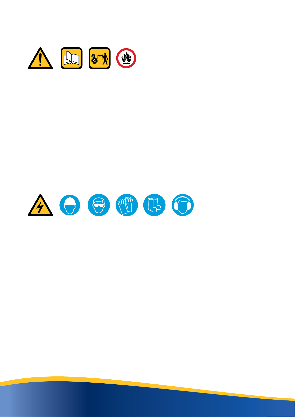
Protect Yourself
Make sure you wear protective clothing and personal safety items.
You May Need
• A Hard Hat
• Safety Goggles
• Hearing Protection
• Foul Weather Clothing
• Reflective Clothing
• Protective Gloves
• Safety Boots
DO NOT wear items of loose clothing, jewellery or other items and tie up any long hair which could
entangle in the controls or other parts of the machine.
Know Your Equipment
Get to know all you how to operate all controls on the machine and the attachments
IF THERE IS SOMETHING IN THE MANUAL WHICH YOU DO NOT UNDERSTAND, CONTACT THE
MACHINE AGENT OR MANUFACTURER AND ASK THEM TO EXPLAIN IT TO YOU.
Danger, Warning And Caution
This symbol below has 3 important meanings when used with the following captions.
DANGER: An IMMINENTLY HAZARDOUS situation that WILL result in DEATH or
VERY SERIOUS INJURY
WARNING: A POTENTIALLY HAZARDOUS situation that COULD result in DEATH
or VERY SERIOUS INJURY
CAUTION: A POTENTIALLY HAZARDOUS situation that MAY result in MINOR
INJURY

www.augertorque.com 1111
Protective And Safety Devices
Keep all protective devices in place and securely fastened. Make sure all guards, shields and safety
signs are properly installed and are in good condition.
Check The Equipment
Before you operate the equipment, take time to check your machine and ensure that all systems
are in good operational order.
• Never operate the equipment with worn, damaged or missing parts. Use only genuine
replacement parts.
• Always ensure that the parent machine is secure and stable with its engine switched off and
hydraulic pipes disconnected before carrying out any maintenance work.
• Check for loose, broken, missing or damaged parts. Have everything put into good repair and
make sure all safety devices are in place.
• Perform all maintenance procedures outlined for the equipment.
• Always protect hands. Select appropriate gloves when handling the equipment during fitting,
removing or adjusting.
• Always protect feet with safety boots.
WARNING: Hydraulic fluid under pressure can penetrate the skin or eyes and cause
serious PERSONAL INJURY, BLINDNESS OR DEATH.
Fluid leaks under pressure may not be visible. Use a piece of wood or thick cardboard to
find leaks. DO NOT USE YOUR BARE HANDS.
Wear safety goggles for eye protection.
If any fluid is injected into the skin, it MUST be surgically removed.
SEE A DOCTOR IMMEDIATELY
Make sure all hydraulic lines are correctly installed
Before applying pressure to the hydraulic system be sure all connections are tight and that lines,
pipes and hoses are not damaged. Before disconnecting hydraulic lines, be sure to relieve all
pressure.
Hazard Classification (Only applicable to ANSI Safety Labels)
DANGER: IMMEDIATE HAZARD! - Failure to understand or obey this
information is likely to result in personal injury or death.
WARNING: Failure to follow these instructions may result in personal
injury or death.
CAUTION: Failure to follow these instructions may result in minor
personal injury or damage to the machine or the vehicle.
NOTICE: This is important information for the proper use of this
equipment. Failure to comply may lead to premature equipment
failure.
CLEAN OR REPLACE THE SAFETY LABELS IF THEY CANNOT BE CLEARLY READ OR UNDERSTOOD
www.augertorque.com 1212
Safety Precautions
NEVER operate or assemble the equipment without fully understanding the operating
instructions of both the equipment unit and the parent machine.
Auger Torque recommends you receive dealer instruction before operating the unit.
NEVER operate the equipment unless you are in good physical condition and mental
health.
NEVER operate the equipment under the influence of any substance (including drugs &
alcohol) which might impair vision.
NEVER operate the equipment with worn, damaged or missing parts. Use only genuine
replacement parts.
NEVER proceed with works before completing a site risks assessment immediately before
commencing work. Nominating the safe work exclusion zone radius for persons and
animals as part of identifying risks and implementing controls.
NEVER allow minors to operate the equipment.
ALWAYS survey the work area before commencing operations. Check for potential hazards,
e.g. Electricity or communication cables etc.
ALWAYS ensure that the parent machine is secure and stable with its engine switched off
before carrying out any maintenance work.
ALWAYS ensure the hydraulic oil supply to the attachment is disconnected by uncoupling
the hydraulic hose connectors before fitting, removing or adjusting the equipment
ALWAYS wear head protection and eye protection when working on the unit.
ALWAYS protect hands. Select appropriate when handling the equipment
during fitting, removing or adjusting the unit.
ALWAYS protect feet. Wear approved safety boots.
ALWAYS follow the parent machine instructions regarding noise protection.
STAY ALERT. Should something break, come loose or fail to operate on your equipment,
STOP WORK, lower equipment to the ground, shut off the engine and lock out hydraulic
supply, inspect the machine and have repairs or adjustments made before resuming
operation.

www.augertorque.com 1313
A
99-5815
99-5429
99-5815
99-5815
99-5429
99-5429
99-5429
99-5815
A
BB
CC
Safety Decals
ALL safety signs listed must be fitted to the machine and must be legible.
Use mild soap and water to clean safety signs - DO NOT use solvent based cleaners
because they may damage safety sign material.
Safety signs are fitted to the machine to warn of possible hazards and MUST be replaced
immediately if they become unreadable or lost.
If the machine is repaired and parts have been replaced on which safety signs were fixed,
ensure new safety signs are fitted before the machine is put into service.
Item Description Qty Part Number
A Read operators manual before operating machine 2 99-5815
B Stand clear of rotating objects 2 99-5429
C Grease points 3 99-5814
www.augertorque.com 1414
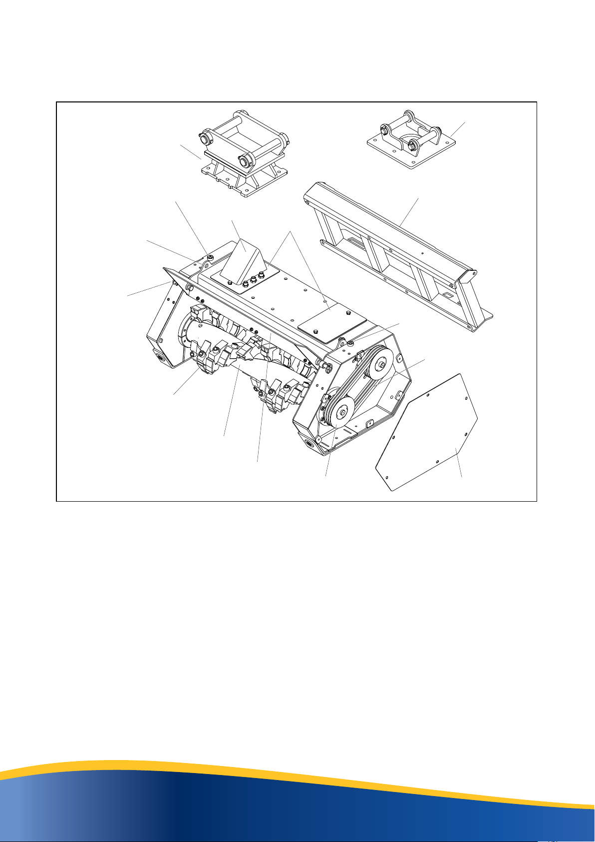
IDENTIFICATION
Typical Setup
Double Pin Hitch
Hitch Raiser Plate
Skid Steer Loader
Mounting Frame
Drive Belts
Tooth
Fixed Tungsten
Drum Tube
3 Groove Pulley
Pressure Gauge
Side Panel
Top Covers
Deflector Door
Door Pin
and Clip
Grease Point
Grease Point
SPECIFICATIONS
VM1000
Standard Gear Motor
Oil Pressure Range 160 - 180 BAR (2320.6 - 2610.7 psi)
Optimum Oil Pressure 180 BAR (2610.7psi)
Oil Flow Range 60 - 70 LPM (15.85 - 18.49 gpm)
Optimum Oil Flow 70 LPM (18.49 gpm)
Suitable For Excavator
5T (11023 lbs) to 10T (22046 lbs)
Skidsteer Compatible
Suitable for machines that can obtain the above pressures and
flow rates
Cutting
Processes trees up to 120 mm (5 in) diameter
VM1500
Standard Piston Motor
Oil Pressure Range 220- 240 BAR (3190.8 - 3480-9 psi)
Optimum Oil Pressure 240 BAR (3480.9 psi)
Oil Flow Range 85 - 95 LPM (22.4 - 25.0 gpm)
Optimum Oil Flow 95 LPM (25.0 gpm)
Suitable For Excavator
10T (22046 lbs) to 15T (33069 lbs)
Skidsteer Compatible
Suitable for machines that can obtain the above pressures and
flow rates
Cutting
Processes trees up to 250mm (10 in) diameter
Lifting
Eye

www.augertorque.com 1515
M12 - 130Nm / 96ft-lb
M16 - 195Nm / 144ft-lb
A
1
2
2
B
MOUNTING OPTIONS
Double Pin Hitch
SAFETY FIRST
ALWAYS work in pairs (2 skilled operatives) whenever Mulcher components are being
assembled or disassembled from the parent machine. Always check the weight of the
attachment and ensure you have the correct equipment for handling it.
ALWAYS check parent machine:
• Is in correct working order
• Is parked correctly on flat ground
• Has its hand brake ON, its hydraulic circuit locked out and its engine switched OFF.
Check that the hitch is of the correct model and type to fit the parent machine.
Ensure hitch and attachment points are clean before fitting.
Use suitably rated lifting equipment if required (see serial plate for weight).
NOTE: If a quick Hitch is fitted to the parent machine, refer to the quick Hitch manufacturer’s
installation instructions for correct fitting procedure. Hitches are available with fixed pins.
DIN 1284
FITTING ensure all components are greased on assembly:
Set the Mulcher unit horizontally, with the side panel towards the parent machine as in (Fig A).
• Place the Hitch on top of the mulcher unit and aline the six fixing holes.
• Fit bolts and washers
• Torque bolts to:
M12 - 130 Nm / 96 ft-lbs.
M16 - 195 Nm / 144 ft-lbs.
To attach a Linch Pin fitting (Fig A,
item 1), align the Pin holes, push the
Pin (1) fully home and fit a linch Pin
(2) at each end.
For additional clearance of the
hydraulic hoses, we recommend using
a Raiser Plate (B).
www.augertorque.com 1616
4
A
2
3
1
1
M12 - 130Nm / 96ft-lb
M16 - 195Nm / 144ft-lb
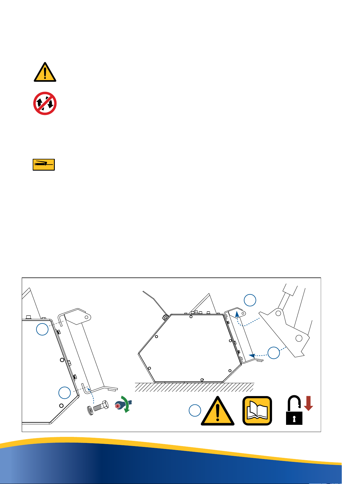
Skid Steer Loader
SAFETY FIRST
ALWAYS work in pairs (2 skilled operatives) whenever Mulcher components are being
assembled or disassembled from the parent machine. Always check the weight of the
attachment and ensure you have the correct equipment for handling it.
ALWAYS check parent machine:
• Is in correct working order
• Is parked correctly on flat ground
• Has its hand brake ON, its hydraulic circuit locked out and its engine switched OFF.
Check that the mounting frame is of the correct model and type to fit the parent machine.
Ensure mounting frame and attachment points are clean before fitting.
Use suitably rated lifting equipment if required (see serial plate for weight).
DIN 1284 FITTING: Ensure all components are greased on assembly:
Fit Mounting Frame to the rear of the Mulcher Unit as in (Fig A, item 1).
• Fit bolts and washers.
• Torque bolts to:
M12 - 130 Nm / 96 ft-lbs.
M16 - 195 Nm / 144 ft-lbs.
2 Slot the top of the parent machine frame under the top edge of the Mounting Frame
or Locating Hooks (refer to parent machine operator’s manual).
3 Swing the parent machine frame to the vertical position.
4 Following the parent machine operator’s manual, ensure that the Mounting Frame is
securely locked in place .

www.augertorque.com 1717
C
A
73Nm/54ft-lb
3
/
4
” BSP
56Nm/41ft-lb
1
/
2
” BSP
25Nm/18ft-lb
1
/
4
” BSP
B
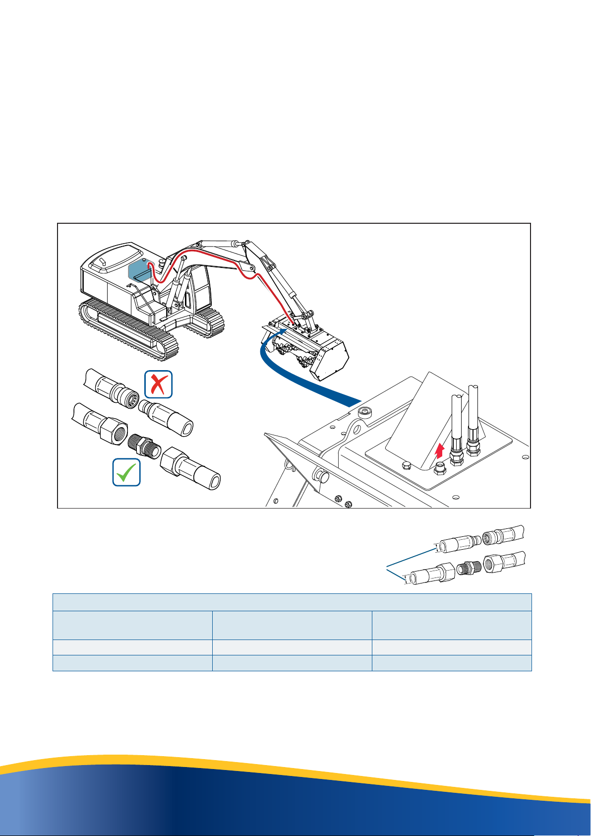
HYDRAULIC CONNECTIONS
WARNING:
Hydraulic fluid under pressure can penetrate the skin or eyes and cause serious
personal injury, blindness or death. Fluid leaks under pressure may not be visible. Use
a piece of card or wood to find leaks. DO NOT use your bare hands. Wear safety goggles
to protect your eyes. If any fluid is injected into the skin, it MUST be surgically removed.
Seek immediate medical attention.
All Auger Torque Mulcher Units require a ‘flow’ and ‘return’ of hydraulic oil from the parent machine’s
auxiliary hydraulic power supply and a free flow return to tank for the case drain to operate
.
When fitting hydraulic hoses, ensure that they are tightened to the correct torque for the hose
fittings (Fig A).
Quick Release Couplers are required for connection to the parent machine, but may not be supplied
with the unit. These can be sourced locally and should be compatible with the auxiliary hydraulic
Quick Release Couplers on the parent machine (Figs B & C). The parent machine auxiliary
hydraulic connections are normally located near the end of the loader arms, excavator dipper.
Quick-Release
Couplings
Parent Machine
CASE DRAIN
OUT
IN
www.augertorque.com 1818
Hoses Specifications Minimum internal diameter
Minimum hydraulic hose requirements
Model Minimum internal hose
diameter (in/mm) Minimum working pressure
Bar/PSI
VM1000 1/2” / 12.7mm 275Bar / 3988PSI
VM1500 3/4” / 19.0mm 280Bar / 4061PSI
Replacement hydraulic hoses MUST be rated equal or greater than the minimum working pressure.
NOTE: When all hoses are correctly connected the Drum rotation is anticlockwise when viewed
from the left hand side of the mulcher.
Case Drain Line Connection
All of the Mulchers must be fitted with a case drain line.
The bulkhead fitting on the top plate of the mulcher must be connected to a line that returns to the
machine’s hydraulic fluid reservoir. The parts required to complete this circuit will vary, depending
on the machine and the hydraulic equipment fitted. Consequently, case drain hose fittings are not
supplied with the Mulcher and must be sourced separately.
When fitting a case drain line, there must be no restrictions to the flow between the Mulcher and
the reservoir. You MUST NOT use quick release couplings.

www.augertorque.com 1919
PREPARATION
CONSIDER the topography (e.g. risk of subsidence, slope angle, position to
embankments and any previous excavation).
Block off work area from bystanders, livestock, etc. Flying debris can cause severe
injury or death. The mulcher is capable of producing large amounts of flying debris in all
directions.
NOTE the type of vegetation, trees and their condition to enable selection of suitable teeth and the
cutting capabilities of the mulcher.
ALWAYS carry out a site survey and risk assessment BEFORE starting work
AVOID underground hazards, such as water / gas / electricity / communication lines etc.
OBSERVE overhead electrical and other utility lines.
Auger Torque Mulcher Units should only be used with parent machines that have an enclosed
operator’s station. Doors and windows MUST be closed when Mulcher is in use.

www.augertorque.com 2020
WORKING PROCEDURE
Before commencing work, ensure that:
The correct hoses are fitted and tightened correctly (See page17).
There are no bystanders within the nominated radius as defined in the risk assessment
completed prior to commencing any works.
You operate only from the operator’s station and are aware when mulching standing
trees, there is a danger of the treetop falling back onto the operator’s cab.
Operation
Set deflector door position, the door should be in the open position when cutting trees or working at height.
It is recommended the door is in the closed position when working at ground level to prevent flying debris
• Start machine and raise mulcher off the ground.
• Set engine speed to tick over and engage mulcher hydraulics.
• Increase engine speed to full rpm.
• Visually check drum rotation (See page18)
If mulcher jams when cutting. Lower mulcher to ground, stop the engine and remove key to prevent
accidental starting. Remove debris from rotor drum.
Excavators;
• When cutting trees, start at a safe operating height for your excavator and cut off the top of the tree.
Position the mulcher over the tree trunk and lower the mulcher. A constant downward pressure should
be maintained to obtain a shatter affect.
• Ground mulching should be done in one direction and long vegetation may take more than one pass.
Skid Steer Loaders
• The hydraulic pressure gauge is visible from the operator’s seat and will show the operator
what the hydraulic system pressure is during operation of the mulcher.
• Smoothly and start forward travel.
• When cutting correctly the pressure gauge should be between:
VM1000 80bar (1160psi) to 180bar (2610psi)
VM1500 80bar (1160psi) to 240bar (3480psi)
• If forward travel is too fast the pressure gauge will increase and the mulcher is likely to stall.
• Slow ground speed to prevent further stalling.
This manual suits for next models
1
Table of contents
Other Auger Torque Lawn And Garden Equipment manuals


