manuals.online logo
Brands
  1. Home
  2. •
  3. Brands
  4. •
  5. Aumuller
  6. •
  7. Control Unit
  8. •
  9. Aumuller M-COM Click Training manual

Aumuller M-COM Click Training manual

Warranty claims require proper and profes-
sional assembly, installation and maintenance
in accordance with national regulations and
manufacturer‘s instructions of the drives.
The safety instructions in the supplied pro-
duct documentation are to be observed.
Strictly observe the information given in this
and in the instructions for installation of
drives when mounting the M-COM® Click.
Details can be found on our website
www.aumueller-gmbh.de
Keep this instruction over the lifetime of the
product.
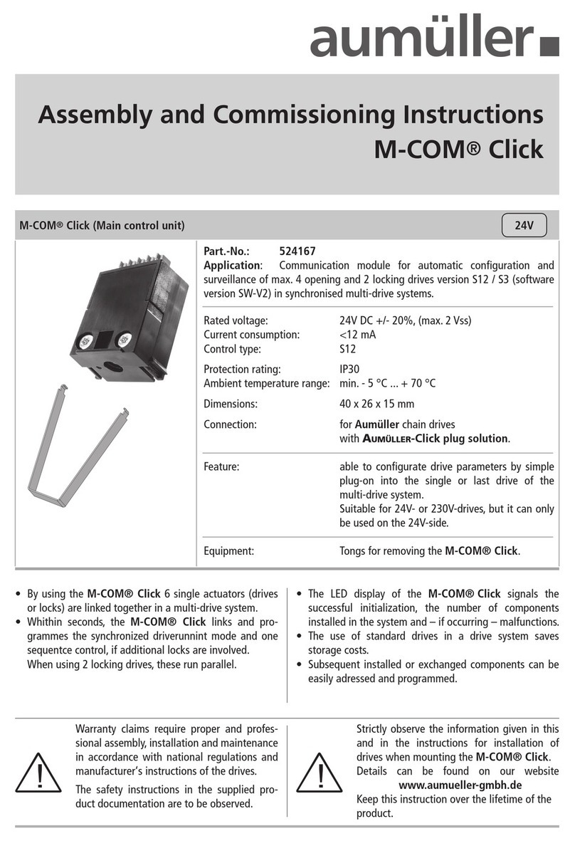
M-COM®Click (Main control unit) 24V
• By using the M-COM® Click 6 single actuators (drives
or locks) are linked together in a multi-drive system.
• Whithin seconds, the M-COM® Click congurates the
synchronization as well as the sequence control, if
additional locking drives are involved. When using 2
locking drives, these run parallel.
• The LED display of the M-COM® Click signals the
successful initialization, the number of components
installed in the system and – if occurring – malfunctions.
• The use of standard drives in a drive system saves
storage costs.
• Subsequent installed or exchanged components can be
easily adressed and programmed.
Assembly and Commissioning Instructions
M-COM®Click
Rated voltage: 24V DC +/- 20%, (max. 2 Vss)
Current consumption: <12 mA
Control type: S12
Protection rating: IP30
Ambient temperature range: - 5 °C ... + 70 °C
Dimensions: 40 x 26 x 15 mm
Connection: Aumüller Click
Feature: Congures drive parameters by simply plug-
ging into the free click slot of a multi-drive
system.
Suitable for 24 V- or 230 V-drives, but it can only
be used on the 24 V-side.
Equipment: Tongs for removing the M-COM® Click.
Part.-No.: 524167
Application: Communication module for automatic conguration and
surveillance of max. 4 opening and 2 locking drives
version S12 / S3 in synchronised multi-drive systems.
Assembly Instruction
M-COM®Click
Commissioning / TesT run
InstallatIon step 1: First commissioning
InstallatIon step 2: Test run,
Malfunction, Troublshooting
Switch on the supply voltage - in CLOSE direction.
Observe the LED reaction of the M-COM®Click.
Check each drive separately with regard to the closing
direction and move to the CLOSED end position.
Completely connect the multi-drive system, including
the white wires.
Insert M-COM®Click in the drive.
Switch on the supply voltage - in CLOSE direction.
Observe the LED reaction of the M-COM®Click .
LED blinks red (Factory settings).
LED starts blinking red / green. The communication
- to the multi-drive operation - is running.
LED blinks green, for each participator once. The pro-
cess is complete.
Compare the numer of devices with the numer of
identied participants.
Check the operation of the multi-drive system according
the instructions for installation the drives.
Troublshooting: LED blinks red.
Check wiring and the system.
Eliminate faults.
Reset the M-COM®Click (see chapter „Reset and re-
initialisation of M-COM®Click)“.
Series connection with M-COM®Click
Note the installation position of the M-COM®
Click !
Drive
M-COM®Click
1
LED
2
LED display
Display State
3s
lights red
Factory settings
(M-COM®Click is reset).
0,5s - 0,5s
blinks red / green (10 times)
Communication - to the multi-drive
operation - becomes set up.
0,5s - 0,5s - 3s
blinks green (X times)
X drives identied
(1 time blinks = identied one drive).
LED display
Display State
0,5s - 0,5s - 3s
blinks green (per drive 1 time)
System is o.k. (can be operated)
drives identied
(1 time blinks = identied one drive).
0,5s - 0,5s - 3s
blinks red (X-times)
When the number of the
learned drives does not coin-
cide with the number of drives
now recognized.
Fault: System is not o.k.
X drives identied
(1 time blinks = identied one drive).
< <<
Assembly Instruction
M-COM®Click
reseT / DemounTing
Reset and reinitialisation of
M-COM®Click
To reset the system: press the pushbutton within the
drilling for about 5 seconds - using a wire (max.
Ø 1mm). The supply voltage is applied.
The LED starts blinking red and lights after successful
reset permanently red.
The factory setting is reached, the learning process will
automatically restart.
Demounting the M-COM®Click
in case exchanging a faulty drive
In case of exchange a faulty drive, demout and reset the
M-COM®Click.
Switch off the supply voltage.
Disconnect the connection cable from the faulty drive.
Demount the faulty drive.
Remove the M-COM®Click from the drive.
Use the pliers to pull the M-COM®Click out of
the drive.
Mount the new / repaired drive and connect it.
Plug the M-COM®Click in the drive.
Switch on the supply voltage - in CLOSE direction.
Reset the M-COM®Click (see chapter „Reset and re-
initialisation of M-COM®Click)“.
Disposing of faulty equipment according to the instal-
lation instructions of drives.
Note The tongs
is included in the scope of
delivery of M-COM®Click.
Drive
Drive
M-COM®Click
1
3
1
2
wire max. ø1 mm
3 mm immersion depth
3
LED display
Display State
0,5s - 0,5s
blinks red (6 times)
M-COM®Click is waiting.
continuous
lights red
M-COM®Click is reset
(Factory settings).
9000021701_V0.2_KW 21.2023
TroublshooTing
Troublshooting:
Exchanging a faulty drive in the multi-drive
system:
Troublshooting:
M-COM®Click take off under voltage:
Switch off the supply voltage.
Disconnect the connection cable from the faulty drive.
Demount the faulty drive.
Mount the new / repaired drive and connect it.
Switch on the supply voltage - in CLOSE direction.
Reset the M-COM®Click (see chapter „Reset and re-
initialisation of M-COM®Click)“.
No adjustment is carried out in case of ex-
change of drives with special program-
ming (e.g. stroke, speed)!
In case of repair please order an exchange drive with the
same parameter assignment as that of the faulty drive.
If the M-COM®Click is removed under voltage and the
drives move, then the drives stop immediately.
Insert M-COM®Click again into the drive.
Put the system back into operation.
4

This manual suits for next models

1

Other Aumuller Control Unit manuals

Aumuller SHEV EMB 8000+ Series Installation and operation manual

Aumuller

Aumuller SHEV EMB 8000+ Series Installation and operation manual

Aumuller M-COM Click Training manual

Aumuller

Aumuller M-COM Click Training manual

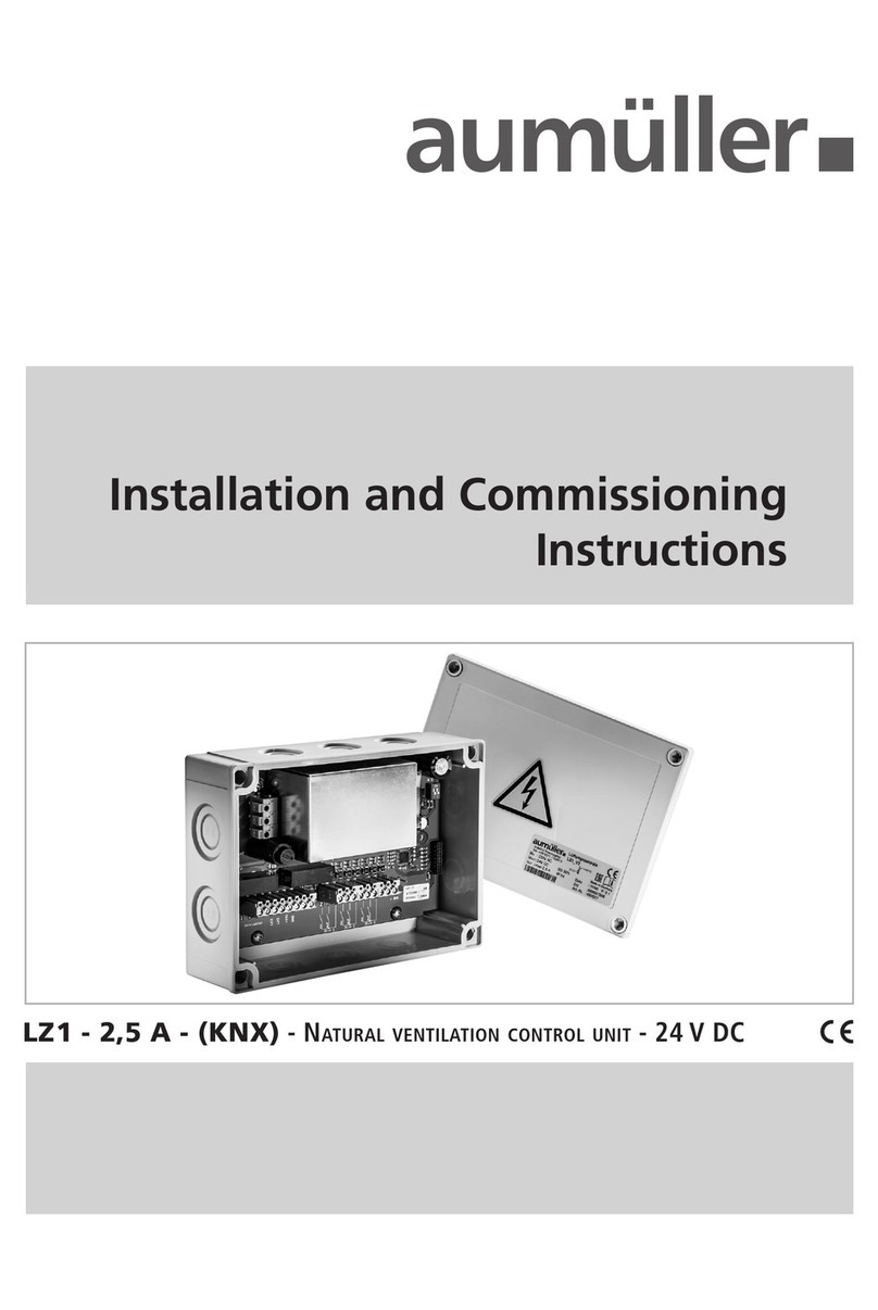
Aumuller LZ1-2,5A-KNX Installation and operation manual

Aumuller

Aumuller LZ1-2,5A-KNX Installation and operation manual

Aumuller EMB 7300 Installation and operation manual

Aumuller

Aumuller EMB 7300 Installation and operation manual

Aumuller EMB 7300 Series Installation and operation manual

Aumuller

Aumuller EMB 7300 Series Installation and operation manual

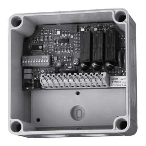
Aumuller USKM Training manual

Aumuller

Aumuller USKM Training manual

Aumuller SHEV EMB 8000+ Series Installation and operation manual

Aumuller

Aumuller SHEV EMB 8000+ Series Installation and operation manual

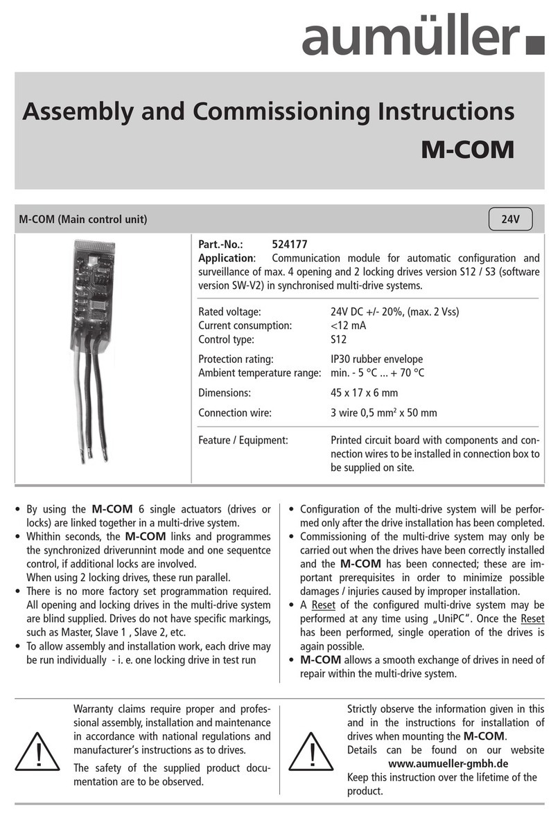
Aumuller M-COM Training manual

Aumuller

Aumuller M-COM Training manual

Popular Control Unit manuals by other brands

Pioneer CX-961 Service manual

Pioneer

Pioneer CX-961 Service manual

Ei Electronics EIB100MRF instructions

Ei Electronics

Ei Electronics EIB100MRF instructions

Forza FDC-BS10KMR user guide

Forza

Forza FDC-BS10KMR user guide

Samson 3254 Mounting and operating instructions

Samson

Samson 3254 Mounting and operating instructions

HeartSine Gateway quick start guide

HeartSine

HeartSine Gateway quick start guide

Metso Jamesbury VAQ214NC Series Installation maintenance and operating instructions

Metso

Metso Jamesbury VAQ214NC Series Installation maintenance and operating instructions

Jung 2072 TSM operating instructions

Jung

Jung 2072 TSM operating instructions

Siemens XDLC installation instructions

Siemens

Siemens XDLC installation instructions

Daikin E8.5064 installation manual

Daikin

Daikin E8.5064 installation manual

General Monitors 610A manual

General Monitors

General Monitors 610A manual

Ditel Kosmos KOS1010 quick start guide

Ditel

Ditel Kosmos KOS1010 quick start guide

ECTIVE SUNDOCK MSP operating instructions

ECTIVE

ECTIVE SUNDOCK MSP operating instructions

ABB WaveLINE 6731-21-500 Installation and operating instructions

ABB

ABB WaveLINE 6731-21-500 Installation and operating instructions

ABB i-bus EIB product manual

ABB

ABB i-bus EIB product manual

HAUTAU RAZ K Installation and operating instructions

HAUTAU

HAUTAU RAZ K Installation and operating instructions

Cube Sense V3 user manual

Cube

Cube Sense V3 user manual

Danfoss 103E5 Installation & user's instructions

Danfoss

Danfoss 103E5 Installation & user's instructions

Eaton Cutler-Hammer Digitrip RMS 510 Instruction leaflet

Eaton

Eaton Cutler-Hammer Digitrip RMS 510 Instruction leaflet

manuals.online logo
manuals.online logoBrands
  • About & Mission
  • Contact us
  • Privacy Policy
  • Terms and Conditions

Copyright 2025 Manuals.Online. All Rights Reserved.