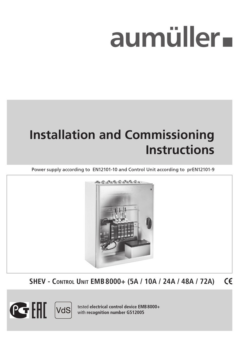
Aumuller SHEV EMB 8000+ Series Installation and operation manual

SHEV - Control Unit EMB 8000+ (5A / 10A / 24A / 48A / 72A)
tested electrical control device EMB8000+
with recognition number G512005
Power supply according to EN12101-10 and Control Unit according to prEN12101-9
Installation and Commissioning
Instructions

2
Installation instruction
SHEV - Control Unit EMB 8000+
08
07
06
05
04
03
02
01
Abbreviations
Warning and Safety Symbols
Target Groups, Intended Use
Safety Instructions, Guidelines and Standards
Overview: EMB 8000+ in the installation
Overview: EMB 8000+ module
Technical Data
Preparing assembly
Information regarding equipment and version of Control Unit
Arrangement, order and connection of modules on standard rail
InstallatIon step 1: Connection: Main power supply
InstallatIon step 2: Connection: Modules to BUS
InstallatIon step 3: Networking of Control Unit
InstallatIon step 4: Connection: Power-Module-Extension PME and Power-Module PM
InstallatIon step 5: Connection: Control-Module CM
InstallatIon step 6: Connection: Sensor-Module SM
InstallatIon step 7: Connection: Drive-Module DM (10 A) / DMX (20 A) / IDM (10 A)
InstallatIon step 8: Connection: Relay-Module RM6 and Connection: IM-K
InstallatIon step 9: Connection: Weather-Module WM
InstallatIon step 10: Connection: BUS-smoke detector and BUS-break-glass units (HSE)
Indicator and Control elements / Fuses
Troubleshooting and repair
Maintenance and Modication
InstallatIon step 11: Modify module congurations
InstallatIon step 12: Enabling operation / completing installation
Storage and Disposal
Warranty and After-Sales Service
Liability
3 - 6
7 - 8
9 - 13
14 - 22
23 - 43
44
45 - 49
50
Contents

3
Installation instruction
SHEV - Control Unit EMB 8000+
AbbreviAtions
Scale units
°C Degree Celsius
A Amperes
Ah Amp-hours
kg Kilogram
m Metres
min Minutes
mm Millimetres
s Seconds
V Volts
PU Packaging Units
Vpp Residual ripple (Voltage Peak-Peak)
W Watts
Ω / k Ω Ohm / Kilohms
Figures
AC Alternating current (50Hz / 60Hz)
DC Direct current
I Electric current
L Length
ME Module space unit (1 ME = 23 mm)
NC Contact „closed“ (normally closed)
NO Contact „opened“ (normally opened)
P Electric power
R Electrical resistance
U Electric voltage
Um Change over switch
Colour abbreviation according to IEC 60757
BK black GY grey VT violet
BN brown OG orange WH white
BU blue PK pink YE yellow
GN green RD red
Index of abbreviations
These abbreviations are used consistently throughout this instruction.
Unless stated differently, all dimensions indicated in this document are in mm.
General tolerances in accordance with DIN ISO 2768-m.
aP Surface mounting
WxHxD Width x Height x Depth
CAN CAN-BUS
CM Control-Module
COM Common connection
DIN German Institute for Standardisation
DM Drive-Module
EN European Standard
IN Input
LON Local Operating Network
OUT Output
PG Price group
PM Power-Module
PS Power supply
RM6 Relay-Module
RWA SHEV – smoke and heat exhaust ventilation
SM Sensor-Module
uP Flash mounting
WM Weather-Module
WRG Wind direction sensor
WArning And sAfety symbols in these instructions:
The symbols used in the instructions shall be strictly observed and have the following meaning:
Failure to comply with the warning notes results
in irreversible injuries or death.
Failure to comply with the warning notes can
result in irreversible injuries or death.
Failure to comply with the warning notes can
result in minor or moderate (reversible) injuries.
Failure to comply with the warning notes can lead
to damage to property.
!
WArning
!
dAnger
!
cAution
note
Useful note
for an optimum installation.
Note regarding the system conguration
setting options via the „Alpha“ conguration
software.
USB
Caution / Warning
Danger due to electric current.
Attention / Warning
Risk of damage to / destruction of Control Unit, drives
and / or windows.
!
01
PrefaCe remark

4
Installation instruction
SHEV - Control Unit EMB 8000+
01
PrefaCe remark
These instructions are intended for personnel trained in
electrical engineering and skilled operators of systems
for natural smoke ventilation (NRA / SHEV) (natural smo-
ke exhaust system / smoke and heat exhaust system) and
natural ventilation via windows, who are knowledgeable
of operating modes and remaining risks of the system.
This device is not intended for use by per-
sons (including children) with physical,
sensory or mental limitations or lacking
experience and / or knowledge.
tArget group
!
WArning
By connecting the window drives with
a control device and their operation the
builder of the complete system becomes
the manufacturer of the power-operated
window! If necessary, it is required to
perform a risk assessment of the comple-
te system in accordance with the Machi-
nery Directive 2006/42/EG when the uti-
lization or operation of the control device
or the connected window drives deviate
from their intended use!
note
intended use
Area of application / Scope of application
This control device is intended for powering and cont-
rolling electromotive operated windows in facade and roof
areas. The prime task of this product, in combination
with the electric window, is to evacuate hot smoke and
combustion gases in case of re to save human lives
and protect property. Furthermore, the electric window
ensures fresh air supplied for natural ventilation of the
building.
Intended use according to the Declaration of Con-
formity
The control device is intended for stationary installation and
electrical connection as part of a building.
In accordance with the attached Declaration of Con-
formity the control device, in combination with
electromotive drives from aumüller, is released
for its proper use at a power-operated window:
• Application for natural ventilation
with an installation height of the drive and
the bottom side of sash of at least 2,5 m above
the oor, or
with an opening width at the HSK of the driven
part of < 200 mm by a simultaneous speed of
< 15 mm/s at the HSK in closing direction.
• Application as NSHEV (natural smoke and heat
exhaust ventilator(s) for ventilation without dual
purpose for ventilation in accordance with EN12101-2.
note
We recommend using exclusively sys-
tem components by Aumüller, because
their compatibility is carefully checked
in the factory. Aumüller shall not assume
liability for the system-compatible func-
tioning of third party components.
Applications and connections other than
explicitly described in these instructions
require the express written consent of
Aumüller. Utilization of applications and
components not expressly authorised by
Aumüller are considered as unintended
use even if their perfect functioning is
proven at commissioning (e.g. approval
under building law).

5
Installation instruction
SHEV - Control Unit EMB 8000+
01
safety InstruCtIons
!
WArning
Area of application
The control device must be used only for its intended pur-
pose. For additional applications, consult the manufacturer
or its authorised dealer.
Installation
These instructions are intended for expert and safety-
conscious electricians and / or qualied personnel familiar
with the electrical and mechanical installation of drives and
control systems.
Mounting material
The required mounting material must be modied to t the
occurring load.
Routing cables and electrical connection
Electrical lines and connections may be routed or instal-
led only by approved specialist contractors. Never operate
drives, Control Units, operating elements and sensors at
operating voltages and connections contrary to the speci-
cations of the manufacturer.
sAfety instructions
It is important to follow these instruc-
tions for the safety of persons. These
instructions must be kept in a safe place
for the entire service life of the products.
The planning and calculation of the
wiring system is the responsibility of
the builder or its agent or the authori-
sed builder and must be performed
according to the statutory provisions.
note
All relevant instructions must be observed for the in-
stallation, specically:
• VDE 0100 Setting up high-voltage systems up to 1000 V
• VDE 0815 Wiring cables
• Specimen Guideline on Conduits German designation
(MLAR).
The types of cable, cable lengths and cross-sections must
be selected in accordance with the manufacturer’s technical
data. If necessary, the cable types must be coordinated with
the competent local authorities and energy supply com-
panies. Low-voltage lines (24 V DC) must be routed
separate from the high-voltage lines. Flexible cables may
not be ush-mounted. Freely suspended cables must be
equipped with strain reliefs.
The power line on-site must be secured se-
parately and provided all poles separators.
After opening of the system housing voltage
carrying parts are exposed. The system must
be separated from the power supply and bat-
tery voltage before each intervention in the
Control Unit of the system.
Clamping points must be checked for tightness of threa-
ded connections and cable ends. Access to junction boxes,
clamping points and external drive control systems must be
ensured for maintenance work.
Commissioning, operation and maintenance
After the installation and after each modication in the
set up all functions must be checked with a trial run.
After the installation of the system is completed the
end-user must be introduced to all important operating
steps. If necessary, he must be advised of all remaining risks /
dangers.
The end-user must be instructed in intended use of the
drives and, if necessary, the safety instructions.The end-user
must be specically instructed that no additional forces,
except for the pressure and tension in the opening and
closing direction of the casement, may be applied to the
spindle, chain or lever of the drive.
Cables must be laid such way that they cannot
be sheared off, twisted or bent during operati-
on. It is recommended to perform an insulati-
on measurement of the system’s line network
and to document this.
note Post warning signs!
Before working on the system, it must be com-
pletely disconnected from the power supply
and emergency power supply (e.g. batteries)
and secured against being switched on again
accidentally. While working in the Control
Unit the workplace must be secured to prevent
unauthorised access. You must ensure that
unauthorised personnel are unable to open
the Control Unit.
!
WArning Check all functions of the system before
releasing it for operation.
The installation instructions of system components (smo-
ke detector, natural smoke and heat exhaust ventilators,
drives, etc.) are part of the documentation for the complete
system and must be kept accessible for authorised quali-
ed personnel, together with the installation and operating
instructions, for the entire service life of the system.
Software terms and conditions
The Control Unit is congured by the factory for the inten-
ded use (standard conguration). The software, especially
developed for this Control Unit, allows a quick and easy
adjustment of the factory setting to the respective re-
quirements. Furthermore, the system status can be saved,
retrieved and printed.

6
Installation instruction
SHEV - Control Unit EMB 8000+
01
safety InstruCtIons
Modiable standard congurations are parti-
cularly emphasized in these instructions. The
functional range of the unlicensed version can
be expanded by activation against payment
(license).
USB
Declaration of Conformity
The control device is manufactured and inspected for
its intended use in accordance with the European guide-
lines. The relevant Declaration of Conformity is at hand.
If the use or operation of the control device or the con-
nected window drives deviate from this a risk assess-
ment must be performed for the complete powered
window system and a Declaration of Conformity according
to Machinery Directive 2006/42/EG issued as well as a
CE labeling obtained.
guidelines And stAndArds
It is essential that the most recent versions of country-
specic laws, regulations, provisions and standards be ob-
served during installation and for electrical connections.
These are for instance:
State building code with special construction regulations
such as:
- Industrial construction guideline
- Venue regulations, etc.
MLAR - Sample Guideline on Conduits German desig-
nation
Provisions of the re protection authorities TAB
(technical connection conditions)
for Utility companies
German Regulations for Occupational Insurance
Schemes, such as:
- ASR A1.6 and 1.7(substitute for BGR 232)
Additional standards and guidelines, such as:
EN 60335-2-103 Safety of household and similar elec-
trical appliances
EN 60730-1 Automatic electrical controls
EN 12101-10 / prEN 12101-9 (ISO 21927-9/10)
Smoke and heat control systems
DIN 4102-12 Functional integrity of electric cable
systems
VDE 0100 Installation of high-voltage systems up
to 1000 V
VDE 0298 Use of cables
VDE 0815 Wiring cables (for telecommunication
and data processing systems)
VDE 0833 Alarm systems
VdS-Guidelines: 2593, 2581, 2580, 2592
Accident prevention regulations, in particular:
- VBG 1 „General rules“ and
- VBG 4 „Electrical systems and equipment“.
For placing on the market, installation and operation out-
side Germany, the relevant national laws, regulations,
standards and safety provisions apply.
The contractor is responsible for proper installation or
operation and the issue of a Declaration of Conformity
according to European guidelines.
The prerequisites of the system (see chapter “SyStemS confi-
guration of Software”) must be checked prior to installation.
The “Software clause for handing over the standard soft-
ware as part of shipments” of the ZVEI (German Electrical
and Electronic Manufacturer’s Association) is accepted as
legally binding upon installation. See our homepage:
.
(www.aumueller-gmbh.de)
We, therefore, recommend protecting the operating system
and system software sufciently against unauthorised inter-
ference (e.g. by using a password) and attending the trai-
ning provided by the manufacturer.
Replacement parts
System components are to be replaced only with spare
parts from the same manufacturer. Liability, warranty and
customer service are void if third-party parts are used. Only
original spare parts from the manufacturer are to be used
for expansions.
Ambient conditions
The product may not be subjected to impacts or falls, or
to vibrations, moisture, aggressive vapours or other harmful
environments, unless the manufacturer has released it for
one or more of these environmental conditions.
• Operation:
Ambient temperature: -5 °C … +40°C
Relative humidity: < 90% up to 20°C;
< 50% up to 40°C;
no formation of condensation
• Transport / Storage:
Storage temperature: 0°C … +30°C
Relative humidity: < 60%
Accident prevention regulations and employer‘s
liability insurance guidelines
For work on or in a building or building part the provisi-
ons and instructions of the respective accident prevention
regulations (UVV and employer‘s liability insurance guide-
lines (BGR /ASR) must be observed and obeyed.
The conguration software of the control de-
vice largely excludes damage caused by incor-
rect settings. As a precaution, we advise that
Aumüller, as manufacturer, cannot assume
liability for damage caused by using Aumüller
software, because Aumüller has no inuence
on a perfect system environment or property-
specic systems conguration.
USB

7
Installation instruction
SHEV - Control Unit EMB 8000+
overvieW: emb 8000+
02
PreParIng assembly
Capiton
Drive line - 24V DC
for smoke + heat exhausting + natural ventilation
Input for ventilation line (max. 10 vent buttons)
Housing of Control Unit
Wind sensor and rain sensor -
(disabled in case of alarm and power loss)
Smoke detector (max. 10 pieces) each SM
Trigger signal from external re alarm system
to smoke detector
Break-glass unit (HSE) (max. 10 pieces) je SM
Temperature controller
Output for signal transduction
Port for network integration
(requires additional module)
BUS-HSE (Break-glass unit) (max. 30 participant)
Bma
3
4
5
6
7
8
9
10
1
2
NHXH-FE 180 / E 90
min. 3 x 1,5mm2
JE-H (St) H FE 180 / E 90
2 x 2 x 0,8
JE-H (St) H FE 180 / E 90
2 x 2 x 0,8
external
re alarm system
JE-H (St) H FE 180 / E 90
4 x 2 x 0,8
J-Y (St) Y - 2 x 2 x 0,8 (Button without display)
J-Y (St) Y - 4 x 2 x 0,8 (Button with display)
JE-H (St) H FE 180 / E 90 - 2 x 2 x 0,8
Operating voltage, primary
230V AC / 400 V AC (50Hz)
Route via external fuse and
switching component!
INFO
INFO
NET
5
6
7
8
9
10
11
3
4
1
2
Note:
Number depends on
the conguration of
the modules.
11
NYM-O 5 x 1,5 oder
NYM-J 7 x 1,5 mm, max. 200 m

8
Installation instruction
SHEV - Control Unit EMB 8000+
overvieW: emb 8000+ module
PreParIng assembly
02
Formula to calculate
the required wire cross-section of a infeed line
A= cross-section of line in mm2
L= line length in m
I= current of connected drives in A
∆U = line voltage drop = 2 V DC
NHXH-FE 180 / E 90
min. 3 x 1,5mm2
NHXH-FE 180 / E 90
min. 3 x 1,5mm2
NHXH-FE 180 / E 90
min. 3 x 1,5mm2
JE-H (St) H FE 180 / E 90
2 x 2 x 0,8 mm, max. 400 m
JE-H (St) H FE 180 / E 90
2 x 2 x 0,8 mm, max. 400 m
JE-H (St) H FE 180 / E 90
2 x 2 x 0,8 mm
max. 400 m
max.
10 pieces
max.
10 pieces
max.
10 pieces
max.
10 pieces
potential-free signal contact
congurable via software
6x potential-free signal contact
congurable via software
congurable
via software
potential-free signal contact
congurable via software
max.
10 pieces
max.
30 participants
max.
10 pieces
JE-H (St) H FE 180 / E 90
2 x 2 x 0,8 mm, max. 400 m
JE-H (St) H FE 180 / E 90
2 x 2 x 0,8 mm, max. 400 m
NYM-O 5 x 1,5 or NYM-J 7 x 1,5 mm, max. 200 m
JE-H (St) H FE 180 / E 90
4 x 2 x 0,8 mm, max. 400 m
JE-H (St) H FE 180 / E 90
4 x 2 x 0,8 mm, max. 400 m
max. 10 A max. 20 A max. 10 A
aumüller S12
J-Y (St) Y - 2 x 2 x 0,8
(Button without display)
J-Y (St) Y
2 x 2 x 0,8 mm, max. 400 m
J-Y (St) Y
2 x 2 x 0,8 mm, max. 400 m
J-Y (St) Y - 2 x 2 x 0,8
(Button without display)
J-Y (St) Y - 4 x 2 x 0,8
(Button with display)
J-Y (St) Y - 4 x 2 x 0,8
(Button with display)
KNX
0 V - 10 V
re alarm
system
„FAS“ re alarm
system
„FAS“
INFO
INFO
INFO
INFO
INFO
INFO
BMZ
BMZ
EMB 8000 +
SD
EMB 8000 +EMB 8000 +EMB 8000 +
IM-K
Prog
EMB 8000 +
EMB 8000 +
EMB 8000 +EMB 8000 +EMB 8000 +
EMB 8000 +
Connection cable CAN-BUS to CM
J-Y (St) Y - 2 x 2 x 0,8, max. 400 m

9
Installation instruction
SHEV - Control Unit EMB 8000+
Electrical data and connected loads
Operating voltage, primary:
Frequency:
Current consumption (primary):
Output voltage of switching
power supply:
Output voltage, drives:
Residual drive voltage ripple:
Swtiching consumption of drive
lines:
195…..253 V AC
50….60 Hz
(depending on version)
26V DC
24V DC nominal (19,3….28 V DC)
< 1V
per Drive-Module DM: max. 10 A
per Drive-Modulel DMX: max. 20 A
per Drive-Module IDM: max. 10 A
Emergency power supply:
Back-up battery voltage (charging
voltage is temperature-compensated):
Nominal capacity:
Nominal current
(during short time operation):
switching power supply 10 A
switching power supply 20 A
Continuous current consumption:
Automatic detectors per signalling
line (term. 1/22, 1/23):
Manual detectors per signalling
line (term. 1-19):
BUS detector each CM
Automatic detetectors per Control
Unit:
Manual detectors per Control Unit:
Detector voltage:
max. 72 hours
2 x 12 V
depending on version
10 A
20 A / 24 A for 3 minute
approx. 30 % of nominal current
max. 10 pieces
max. 10 pieces
max. 30 pieces
max. 60 pieces
max. 60 pieces
≥ 18,2 V
Environmental Conditions (operation)
Ambient temperature range:
Maximum relative air
humidity:
-5…+40 °C
(according to EN 12101 Class 1)
75 % (mean value over lifetime)
90 % (for max. 96 hours)
Mechanical Data
Surface mounted housing:
Protection class:
Housing dimensions:
steel plate painted in RAL 7035
with locking mechanism
(safety cylinder insert, 3 mm)
IP 40 (tested)
IP 54 (not tested)
with wall mounting brackets and seal.
dependent on features of Control Unit
PreParIng assembly
technicAl dAtA
prepAring Assembly
Before starting the installation please check with the delivery note that
the delivery is complete and correct, any complaints received later cannot
be considered. It is required to keep a logbook for the EMB 8000+
which must be accessible to authorised staff at all times.
Scope of delivery: SHEV - Control Unit EMB 8000+
• Installation and Commissioning Instructions
(german and english)
• Test report according to VDE 0113
• Label„Smoke Vent“
• „Maintenance instructions“ stickers
• Key
03
Installation steps:
1.) Mount the housing on the wall in such a manner, that it is per-
manently secured and the Control Unit at the same time easily
accessible for maintenance.
2.) Mount all drives and control elements.Adhere to specications given
in the drive assembly instructions and observe the allowable con-
nection values.
3.) Feed all lines through the cable glands into the Control Unit and
connect same.
On request, the manufacturer can issue the Control Unit circuit diagram.
An EMERGENCY During OPEN, the drives are
activated every 2 minutes within a period of 30
minutes (in accordance with VdS 2580).
!
The available internal emergency power supply (back-
up batteries), if correctly rated and serviced at regular
intervals, ensures that the controller of the Control Unit
opens the connected drives at least twice and
closes them at least once after 72 hours of mains power
supply loss.
!
WArning
Important instructions for safe assembly:
Fully observe all instructions, incorrect assembly
may lead to serious injuries.

10
Installation instruction
SHEV - Control Unit EMB 8000+
PreParIng assembly
Module Maximum
per Control Unit
Maximum
per composite
PME 2 60
PM 1 30
CM+ 1 30
SM 20 570
DM 40 570
DMX 10 300
IDM 30 300
RM6 20 570
WM 1 2
IMK 2 5
The following key data must be taken into account when
dimensioning SHEV Control Units:
Due to the hardware and software, the EMB 8000+ is
limited by the following points. Conguration using the
software is guaranteed within these limits.
1. A maximum of 50 modules per Control Unit (including
CM, excluding PM and PMEs).
The following maximum number of modules of the same
type are supported per Control Unit (in the composite).
All values in the tables refer to the maximum assignment of
the module inputs / outputs. The current values are given for
maintaining the emergency power supply over a period of
72 hours. Other calculation bases on request.
The sum of the self-consumption of all modules in a Control
Unit must not exceed the maximum permissible current of
the Control Unit. To calculate the total power consumption,
the individual consumption of the installed modules must
be added.
The details of the outer diameter of cables refer to the
cable types common in Germany. The wire cross-sections
are given in mm². To maintain the electrical protection class
of the Control Unit housing, only one cable is permitted per
cable entry.
For checking purposes, the total number of cables required
must be determined in accordance with Table 1 and co-
ordinated with the number of cable entries in the Control
Units from Table 4.
2. A maximum of 30 Control Unit in the composite.
3. A maximum of 600 modules in a composite (including
CMs, excluding PMs and PMEs) e.g .: 30 Control Units
with 20 modules or 12 Control Units with 50 modules.
4. 150 Can actuators are supported at the same
time without blocking the triggering CM. Each ad-
ditional CAN actuator results in a recording delay of
9 ms.
CAN actuator is an actuator in a different Control
Unit than the one in which the sensor is located.
Expansion Limitation / systEm Limits
• Number of smoke detector per CM / SM 20 pieces
• Number of Break-glass unit (HSE) per CM / SM 10 pieces
• Number of digital Trigger-unit per CM 30 pieces
• Number of smoke detector per Control Unit 60 pieces
• Number of Break-glass unit (HSE) per Control Unit 60 pieces
• Own power consumption per Control Unit
(see table on the next page)
• Battery capacity / max. Power consumption per Control Unit
(see table on the next page)
• Housing size
• Cable entries
03

11
Installation instruction
SHEV - Control Unit EMB 8000+
Maximum allowable intrinsic current consumption
of all Control Unit modules
Switching power supply
/ backup battery 7 AH 12 AH 17 AH 24 AH 38 AH
42 mA 120 mA 140 mA 240 mA 350 mA
70 mA 120 mA 200 mA 300 mA
80 mA 170 mA 300 mA
100 mA 300 mA
10 a
24 a
48 a
72 a
PreParIng assembly
The maximum allowable number of modules can be
easily determined by using the tables below. Only the
intrinsic consumption by the modules must be added.
The sum may not exceed the allowable value.
If this should be the case, either the number of modules
must be reduced or a Control Unit with a higher output
selected.
note
Because of the intrinsic power consumption of the
modules, their allowable number depends on the
version of the Control Unit.
In selecting the back-up batteries, the bridging time for
emergency power operation during a power failure must
be taken into account.
Note that the back-up battery type and any
Power-Module-Extension(s) PME used be congured
via the system software.
The housing size is determined by the number of
modules and their arrangement, the number of
required switching power supplies and the size of the
back-up batteries. Furthermore, attention must be paid
to the required cable feedthroughs within the Control
Unit housing, the number of which is dependent on the
size of the housing.
Use only back-up batteries with VdS approval!
How many ventilation groups are to be connected?
The Drive-Module DM enables a maximum current consumption of 10 a
for one ventilation group (DMX max. 20 a).
How many ventilation groups are to be connected?
The Control-Module CM (rst re compartment) is required once in any
case. Each additional re compartment requires one Sensor-Module SM.
A maximum of 10 detectors may be connected to one signalling line.
Is there a control required for ventilation via wind and rain
sensors or a wind direction-dependent opening and closing in
case of re?
If so, a Weather-Module WM is required.
Should several Control Units be switched as a system unit via
CAN-BUS?
If so, adhere to the instructions for installation and commissioning
of the module. Conguration requires the licensed system software
of the manufacturer.
!
note
Determining the right equipment for the
Control Unit
In order to be able to determine the right version and equipment of
the Control Unit without a problem, the following procedure is recom-
mended:
How high is the maximum required drive current?
The maximum drive current determines the number of of switching po-
wer supplies as well as the number of Power-Module-Extensions PME.
One Power-Module PM or a single PME can provide a maximum of
24 a each via connected power supplies.
Important criteria for selection of back-up batteries for the
emergency power supply are:
• the maximum drive current
• the number and types of modules
• the number and types of connected detector
!
USB
notes on the control unit equipment And version
Intrinsic module consumption
with back-up battery voltage 24 V
Power-Module PM = 16,1 mA
PM-Extension PME = 0,0 mA
Control-Module CM = 34,0 mA
Sensor-Module SM = 12,6 mA
Drive-Module IDM = 4,6 mA
Drive-Module DM = 5,3 mA
Drive-Module 230 V 230V DM = 7,0 mA
Drive-Module DMX = 5,3 mA
Weather-Module WM = 13,0 mA
Relay-Module RM6 = 4,2 mA
KNX-Module IM-K = 3,7 mA
03
Calculating: maximum allowable number of
modules
In order to guarantee a high degree of adaptability to the variety of
structural requirements, the emB 8000+ is designed as a modular
SHEVS and ventilation system with regard to its digital BUS system
as well as its hardware. This is how re compartments as well as their
furnishing with ventilation and drive lines can be optimally adapted to
particular requirements with use of the relevant modules.
However, the number of modules per Control Unit is limited by the
safety requirements outlined in EN 12101-10 with regard to capacity
and emergency power supply. In case of re, the system must also
function reliably during a power failure and guarantee smoke and heat
ventilation. Because the modules themselves have their own current
consumption (with the exception of the Power-Module-Extension PME),
their number is therefore dependent on the version of the control
unit and the backup batteries used for the emergency power supply.
Intrinsic consumption
of backup battery powerd detectors
Break-glass main unit HSE = 1,2 mA
Break-glass seccondary unit HSE-N = 0,0 mA
Optical smoke detector ORM = 0,1 mA
Wind direction sensor WRG = 7,1 mA
BUS Break-glass unit BUS-HSE = 2,8 mA
BUS Smoke detector BUS-RM = 1,0 mA

12
Installation instruction
SHEV - Control Unit EMB 8000+
Following module requirement as an example
PreParIng assembly
Space requirement for modules
Once the required number of modules is determined, their space requi-
rement on the standard rail can be easilycalculated with the respective
module width:
USB
Main functions of the modules:
• The Power-Module PM provides - depending on the switching power
supply - 5 a, 10 a or 24 a.
• One Power-Module-Extension PME provides an additional 24 a.
• The Control-Module CM or Sensor-Module SM have at their disposal
three signalling lines with a max. of 10 detectors in each case per
signalling line and an option to connect ventilation controls.
• The Drive-Module DM has at its disposal one drive line with up to
max. 10 a (DMX max. 20 a) switching current. The triggering of
gas pressure generators or magnetic clamps is possible with appro-
priate software conguration. The connection of ventilation con-
trols and operational status displays is intended.
• The Weather-Module WM for connection of wind and rain sensors and
/ or wind direction nders is required only once (normally).
The difference between the Control-Module CM and the
Sensor-Module SM is that the Control-Module CM must
be employed only once and obligatorily for the rst re
compartment. The CM has in addition a USB port and its
ventilation control commands are by default superior to
all ventilation groups (joint closing).
Space requirement for modules
2 ME / approx. 46 mm 1 ME / approx. 23 mm
Power-Module
Power-Module-Extension
Drive-Module
Control-Module
Sensor-Module
Drive-Module
Relay-Module
KNX-Module
Weather-Module
PM
PME
DMX
CM
SM
DM / IDM /
230V DM
RM6
IM-K
WM
03
34,0
The modules‘ total own current consumption amounts to
107,4 mA. The appropriate versions of the respective Control
Unit can be determined from the top table.
If the Drive-Modules are utilized with their maximum current
consumption as in the example above, there will be a total drive
current requirement of 60 a (4 x DM plus 1 x DMX).
The appropriate Control Unit would be in this case the
emB 8000+ / 72 a with 2 x 38 Ah.
The emB8000+ / 72 a with 2 x 24 Ah would be under-
dimensioned because of its modules‘ intrinsic consumption of
107,4 mA!

13
Installation instruction
SHEV - Control Unit EMB 8000+
PreParIng assembly
Connection of modules
When connecting the modules, one must differentiate between three
kinds of connections:
Connection to the main power supply of
• Power-Module PM,
• Power-Module-Extension PME,
• Drive-Module DM / DMX / IDM
All modules with connection to the main power supply are secured with
fuses. BUS connection (ribbon cable) of all modules on the bottom of
the module, with the exception of the Power-Module-Extension PME. The
communication between PME and PM is made via ribbon connection
on top of the module.
If the modules are arranged on several standard rails, a special BUS
cable (particular length) must connect the BUS on the lower standard rail
with that on the upper standard rail.
Connection of external components (detectors, drives, etc.) via plug
terminals on top of the module.
Arrangement and order of modules
The modules are mounted on the standard rail directly next to each other.
Following module arrangement must be absolutely adhered to:
• The Power-Module PM and the Power-Module-Extension PME must
be mounted to the extreme left and as the rst element on the
standard rail. Concurrently, the Power-Module-Extensions PME are
always placed to the left of Power-Module PM.
• The Power-Module PM is followed to the right by the Control-Module
CM (which is normally followed by one Drive-Module DM or DMX or
IDM).
03
ArrAngement, order And connection of modules on the stAndArd rAil
Arrangement / order of modules on standard rail
IDM IDM IDM
EMB 8000 + EMB 8000 +
USB
SD
Reset
EMB 8000 + EMB 8000 + EMB 8000 + EMB 8000 + EMB 8000 + EMB 8000 + EMB 8000 + EMB 8000 + EMB 8000 + EMB 8000 +
USB USB
SD SD
Reset Reset
Minimum
features:
With one
Power-Module-Extension PME:
With two
Power-Module-Extensions PME:
Arrangement of modules on standard rail - subdivided into re compartments
EMB 8000 + EMB 8000 + EMB 8000 + EMB 8000 + EMB 8000 + EMB 8000 + EMB 8000 + EMB 8000 + EMB 8000 +EMB 8000 +
USB
SD
Reset Reset Reset
Fire compartment
1
CM SM SMDM (X)
IDM
DM (X)
IDM
DM (X)
IDM
DM (X)
IDM
DM (X)
IDM
DM (X)
IDM
WM
Fire compartment
2
Fire compartment
x
Any further module arrangement
is application-dependent.
For reasons of clarity, it can be
subdivided into re compart-
ments (Control-Module CM follo-
wed by Sensor-Module SM) with
the required number of ventila-
tion groups (= Drive-Modules
DM / DMX / IDM).
If a Weather-Module WM is used,
it should round off the order of
the modules.

14
Installation instruction
SHEV - Control Unit EMB 8000+
InstallatIon step 1:
connection: mAin poWer supply
InstallatIon step 1:
ConneCtIon: maIn Power suPPly
04
Connection of main power supply:
Power-Module pm with two Power-Module-Extensions pme and three switching power supplies 72 a
Drive-Module
Dm / DmX
Drive-Module
Dm / DmX
Drive-Module
Dm / DmX
Power-Module
pm
Power-Module-
Extension
pme
1
Power-Module-
Extension
pme
2
Only connect when disconnected from the mains pow-
er supply! Switch off power supply and secure against
reconnection! Disconnect batteries!
!
The max. power consumption per Drive-Modules DM /
DMX / IDM, which can be connected to a switching
power supply with PM or PME depends on the respective
switching power supply (5 a, 10 a, 24 a).
e.g. Switching power supply 10 a with one DM with max. 10 a current
consumption. Possible, however, are if need be also two DM with
two ventilation groups with a maximum current consumption of only
5 a.
e.g. Switching power supply 24 a for two DM with max. 10 a current
consumption each. If need be, however, four DM, in as far as
the maximum current consumption doesn‘t exceed 10 a per
DM and 24 a total (analogueously this applies to Drive-Module
DMX).
If this has not been done already in the factory, all connections
for the internal power supply and back-up batteries must be
made. This includes connection of the switching power supplies
to Power-Module PM and if need be PME as well as placement
of the back-up batteries within the Control Unit housing and its
connection. In addition, all Drive-Modules DM / DMX / IDM must be
connected to the main power supply. No other modules require a con-
nection to the main power supply.
Operation display (green)
Operation display (green)
Operation display (green)
Operation display (green)
Operation display (green)
Operation display (green)
Status display (green)
Status display (green)
Status display (green)
Fault display (yellow)
Fault display (yellow)
Fault display (yellow)
Fault display (yellow) Alarm (EMERGENCY-OPEN) display (red)
Alarm (EMERGENCY-OPEN) display (red)
Alarm (EMERGENCY-OPEN) display (red)
Display drives OPEN (red)
Display drives OPEN (red)
Display drives OPEN (red)
Display drives CLOSE (green)
Display drives CLOSE (green)
Drive buttons
Drive buttons
Drive buttons
open
open
open
Fuse
Fuse
Fuse
FuseFuse
Fuse
close
close
close
BUS
BUS
BUS
BUS
BUS
BUS
to
next
DM(X)
to
next
DM(X)
to
next
DM(X)
Note max. allowable
current consumption!
Note max. allowable
current consumption!
Note max. allowable
current consumption!
Note order of connections!
Note order of connections!
Note order of connections!
Pay attention
to polarity !
Switching power supply
Switching power supply
Switching power supply
BU
BU
BU
RD
RD
RD
RD
RD
RD
RD
RD
RDRD
RD
RD
RD
RD
RD
RD
10 a or 24 a
with 24 a
with 10 a
RD
RD
RD
RD
RD
RD
RD
RD
RD
RD
BUS to
CM
RD
BU
BU
BUBU
BU
BU
BU
BU
BU
BU
Power supply
Power supply
Power supply
Power supply
Power supply
Power supply
Back-up batteries
Back-up batteries
Back-up batteries
Back-up batteries
Back-up batteries
Back-up batteries
Drive-Module DM
Drive-Module DM
Drive-Module DM
Drive-Module DM
Drive-Module DM
Drive-Module DM
BU
BU
BU
BU
BU
BU
BU
BU
BU
BU
BU
BU
BU
BU
Note that the type of back-up battery and eventually used Power-Module-Extension(s) PME
must be congured via the system software.
Use only back-up batteries with VdS approval!
USB
Back-up
battery 1
12 V
Back-up
battery 2
12 V
Display drives CLOSE (green)

15
Installation instruction
SHEV - Control Unit EMB 8000+
InstallatIon step 1:
ConneCtIon: maIn Power suPPly
Connection of main power supply:
Power-Module pm with one switching power supply 10 a or 24 a
Connection of main power supply:
Power-Module pm with one power modul extension pme and two switching power supplies
24 a10 a
04
48 a
Drive-Module
Dm / DmX
Drive-Module
Dm / DmX
Drive-Module
Dm / DmX
Power-Module
pm
Power-Module
pm
Power-Module-
Extension
pme
BUS to
CM
Operation display (green)
Operation display (green)
Status display (green) Fault display (yellow)
Fault display (yellow) Alarm (EMERGENCY-OPEN) display (red)
Display drives OPEN (red)
Display drives CLOSE (green)
Drive buttons
open
FuseFuse
close
BUS
BUS
to
next
DM(X)
Note max. allowable
current consumption!
Note order of connections!
Pay attention to polarity !
Back-up
battery 1
12 V
Back-up
battery 1
12 V
Back-up
battery 2
12 V
Back-up
battery 2
12 V
Switching power supply
BU
RD
RD
RD
RD
10 a or 24 a
with 24 a
with 10 a
RD
RD
RD
BU
BU
BU
Power supply
Power supply
Back-up batteries
Back-up batteries
Drive-Module DM
Drive-Module DM
BU
BU
BU
BUS to
CM
Operation display (green)
Operation display (green)
Operation display (green)
Operation display (green)
Status display (green)
Status display (green)
Fault display (yellow)
Fault display (yellow)
Fault display (yellow)
Alarm (EMERGENCY-OPEN) display (red)
Alarm (EMERGENCY-OPEN) display (red)
Display drives OPEN (red)
Display drives OPEN (red)
Display drives CLOSE (green)
Display drives CLOSE (green)
Drive buttons
Drive buttons
open
open
Fuse
Fuse
Fuse
Fuse
close
close
BUS
BUS
BUS
BUS
to
next
DM(X)
to
next
DM(X)
Note max. allowable
current consumption!
Note max. allowable
current consumption!
Note order of connections!
Note order of connections!
Pay attention
to polarity !
Switching power supply
Switching power supply
BU
BU
BU
BU RD
RD
RD
RD
RD
RD
RD
RD
RD
RD
RD
RD
RD
RD
10 a or 24 a
with 24 a
with 10 a
RD
RD
RD
RD
RD
BU
BU
BU
BU
BU
BU
BU
BU
Power supply Power supply
Power supply Power supply
Back-up batteries Back-up batteries
Back-up batteries Back-up batteries
Drive-Module DM Drive-Module DM
Drive-Module DM Drive-Module DM
BU
BU
BU
BU
BU
BU

16
Installation instruction
SHEV - Control Unit EMB 8000+
BUS connection at the bottom
BUS connection at the top PME - PME - PM
Since we are dealing with a digital BUS, the modules can be intercon-
nected with the ribbon cable on the bottom of the module independent
of their function within the system.
The only exception is the Module-Extension PME. Its connection with the
Power-Module PM is made with the narrow ribbon cable on the top of
the module.
Only connect when disconnected from the mains
power supply! Switch off power supply and secure
against reconnection! Disconnect batteries!
10 a 24 a 72 a48 a5 a
InstallatIon step 2:
connection: modules to bus
InstallatIon step 2:
ConneCtIon: modules tobus
04
PME
PME
PME
PME
PM
PM
CM
CM
DM(X)
DM(X)
etc.
etc.
etc.
After Power-Module PM
always rst Control-Module CM
All further connections
at the bottom
with 1 x PME
with 2 x PME
Connect modules from PM only diagonally at the bottom (to the rigth):
Connect diagonally at the top only PM with PME 1 (and PME 2):
At PM to PME 1 (and PME 2)
no connection at the bottom

17
Installation instruction
SHEV - Control Unit EMB 8000+
04
Bus topology diagram
Use of repeaters
Settings of the DIP switches on the CM
Basics:
Up to 30 EMB 8000+ Control Units can be networked with one another
via the „OnBoard“ CAN bus interface. The maximum cable length for the
entire bus segment is 400 meters (cable type Y-ST-Y 2 x 2 x 0.8 mm).With
different cable types, the maximum cable length can vary signicantly.
A CAN repeater must be used for longer bus segments.
In order to network the Control Units, the licensed conguration Soft-
ware Alpha required. The bus topology must always be built up in series,
EMB 8000+ EMB 8000+ EMB 8000+ EMB 8000+ EMB 8000+
EMB 8000+ EMB 8000+ CAN
Repeater
100 kbits
EMB 8000+ EMB 8000+
stub lines or ring lines are not permitted. The shield of the bus cable
may only be connected on one side (asymmetrical), the ground of two
Control Units may not be connected via the bus cable in order to avoid
interference. The integrated terminating resistor (120) must be activated
using a DIP switch on the rst and last EMB 8000+ in the composite; the
integrated resistor must be deactivated using a DIP switch on all other
Control Units in the composite.
InstallatIon step 3:
networkIng ofControl unIt
nstallatIon step 3: nEtworking of ControL Unit
On the repeater itself, a 120 resistor must also be
used on each CAN bus segment, as the repeater
galvanically separates the two bus segments!
note
CM
CM
CM
46
ON OFF ON
45
47
46
45
47
46
45
47
DIP switch ON
DIP switch ON
Apply shield:
Apply shield:
yes
yes
yes
yes
yes
no
yes
no
no
no
no
no
no
yes
no
yes
Control Unit 1
Control Unit 1
Control Unit 2
Control Unit 2
Control Unit NControl Unit 29
Control Unit 29
Control Unit 30
Control Unit 30
DIP switch OFF
DIP switch OFF
DIP switch OFF
Maximum 400 meters (Y-St-Y 2 x 2 x 0,8)
Maximum 400 meters (Y-St-Y 2 x 2 x 0,8) Maximal 400 Meter (Y-St-Y 2 x 2 x 0,8)
DIP switch OFF
DIP switch OFF
DIP switch ON
DIP switch ON
First
Control Unit
DIP
switch
DIP
switch
DIP
switch
Control
Unit(s)
Last
Control Unit
Bottom view of the CM

18
Installation instruction
SHEV - Control Unit EMB 8000+
04
Connection diagram: CAN-composite
The cable length between the terminal block and the CM module must be a maximum of 2 meters
and must be YV 3 x 0,8mm (twisted) cable development (pre-wired at the factory.)
InstallatIon step 3:
networkIng ofControl unIt
Connection diagram: CAN-composite
47 45 46
CM
47 45 46
CM
47 45 46
CM
Procedure when setting up a CAN system:
• Set up and assemble all Control Units.
• Lay and connect the bus cables between the system.
• Connect to the rst system.
• Start the Alpha conguration software and select the EMB 8000+
plug-in.
• Set and save the CAN address in the „Start options“ (e.g. 1 of 3).
• Repeat this process for all other Control Units (e.g. 2 of 3 and 3 of 3).
• When all CAN addresses have been distributed, the entire network
can be read out completely and programming can be started.
First Control Unit Control Unit(s) Last Control Unit
Switch position:
Slider towards LAN connector
Switch position:
Slider towards
CAN-BUS terminal
Switch position:
Slider towards LAN connector
Connect the shielding on one side
of the cable with the metal housing!
Cable type to be used:
Y-ST-Y 2x2x0,8mm,
Twisted pair cable
with shield
terminal
EMB 8000+ Virtuelle Zentrale
Zentrale konfigurieren
Werkseinstellung
Formatieren
Backup einspielen
Zenrale
CAN Adressen
Wifi-Einstellungen
Wartung
Firmware Update
lokale Adressen
letzte Adresse
EMB 8000+ Virtuelle Zentrale
Zentrale konfigurieren
Werkseinstellung
Formatieren
Backup einspielen
Zenrale
CAN Adressen
Wifi-Einstellungen
Wartung
Firmware Update
lokale Adressen
letzte Adresse

19
Installation instruction
SHEV - Control Unit EMB 8000+
04
InstallatIon step 3:
networkIng ofControl unIt
CAN Checklist
Test measurement CAN bus cabling
CAN Checklist
What you should denitely check before you congure.
❐Are all Control Units switched on / under voltage?
(Mains and battery)
❐Are all Control Units correctly addressed?
(no address is missing, no address is duplicated)
❐Has the wiring been carried out correctly?
(Line wiring, no branch or ring lines)
❐Has the correct cable been used?
Y-(St)-Y 2 x 2 x 0,8
❐Has the maximum cable length been observed?
(400 meters, rst to last Control Units)
❐re the DIP switches for the resistors set correctly?
(rst and last Control Units ON, all others OFF)
❐Is the shield of the bus cable correctly applied?
(asymmetrical, only one end on the metal housing of the Control
Unit, never connect the ground of several control panels via the
BUS cable)
❐Is the maximum line between the CAN terminal block and the
CM 2 meters long and with YV 3 x 0,8mm (twisted)?
❐Was the cabling measurement successful?
(see test measurement, expected result between 60 and 90 )
If a repeater is used (due to the length of the cable),
the following must also be checked:
❐Is the repeater correctly set using the dip switch?
(100 kbits)
❐Have the two end resistors been activated by jumpers on the
repeater? (120 )
❐The cabling measurement must be carried out for each segment,
if all measurements were successful (see test measurement,
expected result between 60 and 90 )
All specied values (cable length, resistance at the repeater, measure-
ment results, etc.) always refer to the cable types recommended by
aumüller Y-(St)-Y 2 x 2 x 0,8 mm .
If you use a different cable type (e.g. JE-H (St) H FE 180 /
E90 2x2x0,8mm) please contact us at the planning stage in order to be
able to consider possible deviations in cable lengths, resistances, etc.
at the planning stage.
Structure and measurement result
Requirement: Expected measurement result:
• All components tension-free.
• Everything clamped.
• End resistors congured correctly.
• approximately 60 . . . 90
EMB 8000+ EMB 8000+ EMB 8000+ EMB 8000+
4546 47
CAN_H
CAN_L
Shield
4546 47
CAN_H
CAN_L
Shield
4546 47
CAN_H
CAN_L
Shield
4546 47
CAN_H
CAN_L
Shield
Control Unit 1Control Unit 2Control Unit NControl Unit 30
Finale ACTIVE Finale ACTIVEFinale INACTIVE
Ohm meter
Finale INACTIVE

20
Installation instruction
SHEV - Control Unit EMB 8000+
!
Cable installation must be in compliance with applicable
legal requirements.
10 a 24 a 72 a48 a5 a
overvieW of connection of externAl components
Line length and cross-section A (drives) depend on the type of drive and
on the number of drives. Line length and cross-section can be determined
from the following formula:
Formula to calculate
the required wire cross-section of an infeed line
A = cross-section of line in mm2
L = line length in m
I = current of connected drives in A
∆U = line voltage drop = 2 V DC
Allowable connection values:
Terminal cross section:
min. 0,14 mm2 / max. 1,5 mm2for a/ B/ C/ D/ e/ F/
G/ H/ J/ l/ m
min. 0,14 mm2 / max. 2,5 mm2for K (drives)
(total) (length infeed line)
(voltage drop)
overvIew ofConneCtIon ofexternal ComPonents
a= display, max. 0,1 A
cable length: max. 400 m
B= parallel switching of max. 10 break-glass unit buttons
cable length: max. 400 m
C= parallel switching of max. 10 smoke detectors
cable length: max. 400 m
D= parallel switching of max. 10 ventilation buttons
cable length: max. 400 m
e= potential-free contacts,
max. 42 V, 0,5 A
F= sensors, 24V DC, 0,5 A
cable length: max. 400 m
G= analogue inputs, 24 V DC, 4 ... 20 mA
cable length: max. 400 m
H= other inputs / outputs, 24 V DC, max. 0,5 A
J= rain sensor,
cable length: max. 200 m
K= current and cable length depends on the drives
l= analogue input for sensors
max. 24 V, 0,5 A
m= max. 30 participant
(BUS-HM / BUS-RM)
cable length: max. 400 m
04
Other manuals for SHEV EMB 8000+ Series
1
This manual suits for next models
6
Other Aumuller Control Unit manuals
Aumuller
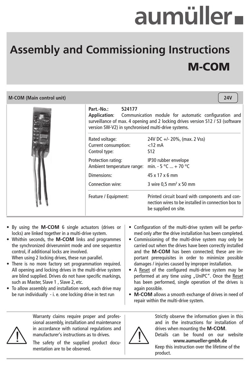
Aumuller M-COM Training manual
Aumuller
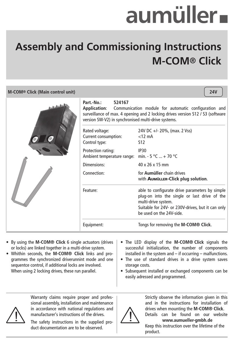
Aumuller M-COM Click Training manual
Aumuller
Aumuller SHEV EMB 8000+ Series Installation and operation manual
Aumuller
Aumuller USKM Training manual

Aumuller
Aumuller M-COM Click Training manual
Aumuller
Aumuller EMB 7300 Installation and operation manual
Aumuller
Aumuller LZ1-2,5A-KNX Installation and operation manual

Aumuller
Aumuller EMB 7300 Series Installation and operation manual
