12
Installation instruction
SHEV - Control Unit EMB 8000+
Maximum allowable intrinsic current consumption
of all Control Unit modules
Switching power supply
/ backup battery 7 AH 12 AH 17 AH 24 AH 38 AH
42 mA 120 mA 140 mA 240 mA 350 mA
70 mA 120 mA 200 mA 300 mA
80 mA 170 mA 300 mA
100 mA 300 mA
10 a
24 a
48 a
72 a
PreParing assembly
10 A 24 A 72 A48 A5 A 10 a 24 a 72 a48 a5 a
The maximum allowable number of modules can be
easily determined by using the tables below. Only the
intrinsic consumption by the modules must be added.
The sum may not exceed the allowable value.
If this should be the case, either the number of modules
must be reduced or a Control Unit with a higher output
selected.
note
03
Because of the intrinsic power consumption of the
modules, their allowable number depends on the
version of the Control Unit.
In selecting the back-up batteries, the bridging time for
emergency power operation during a power failure must
be taken into account.
Note that the back-up battery type and any
Power-Module-Extension(s) PME used be congured
via the system software.
The housing size is determined by the number of
modules and their arrangement, the number of
required switching power supplies and the size of the
back-up batteries. Furthermore, attention must be paid
to the required cable feedthroughs within the Control
Unit housing, the number of which is dependent on the
size of the housing.
Use only back-up batteries with VdS approval!
How many ventilation groups are to be connected?
The Drive-Module DM enables a maximum current consumption of 10 a
for one ventilation group (DMX max. 20 a).
How many ventilation groups are to be connected?
The Control-Module CM (rst re compartment) is required once in any
case. Each additional re compartment requires one Sensor-Module SM.
A maximum of 10 detectors may be connected to one signalling line.
Is there a control required for ventilation via wind and rain
sensors or a wind direction-dependent opening and closing in
case of re?
If so, a Weather-Module WM is required.
Should several Control Units be switched as a system unit via
CAN-BUS?
If so, adhere to the instructions for installation and commissioning
of the module. Conguration requires the licensed system software
of the manufacturer.
note
Determining the right equipment for the
Control Unit
In order to be able to determine the right version and equipment of
the Control Unit without a problem, the following procedure is recom-
mended:
How high is the maximum required drive current?
The maximum drive current determines the number of of switching po-
wer supplies as well as the number of Power-Module-Extensions PME.
One Power-Module PM or a single PME can provide a maximum of
24 a each via connected power supplies.
Important criteria for selection of back-up batteries for the
emergency power supply are:
• the maximum drive current
• the number and types of modules
• the number and types of connected detector
USB
notes on the control unit equipment And version
Calculating: maximum allowable number of
modules
In order to guarantee a high degree of adaptability to the variety of
structural requirements, the emB 8000+ is designed as a modular
SHEVS and ventilation system with regard to its digital BUS system
as well as its hardware. This is how re compartments as well as their
furnishing with ventilation and drive lines can be optimally adapted to
particular requirements with use of the relevant modules.
However, the number of modules per Control Unit is limited by the
safety requirements outlined in EN 12101-10 with regard to capacity
and emergency power supply. In case of re, the system must also
function reliably during a power failure and guarantee smoke and heat
ventilation. Because the modules themselves have their own current
consumption (with the exception of the Power-Module-Extension PME),
their number is therefore dependent on the version of the control
unit and the backup batteries used for the emergency power supply.
Intrinsic module consumption
with back-up battery voltage 24 V
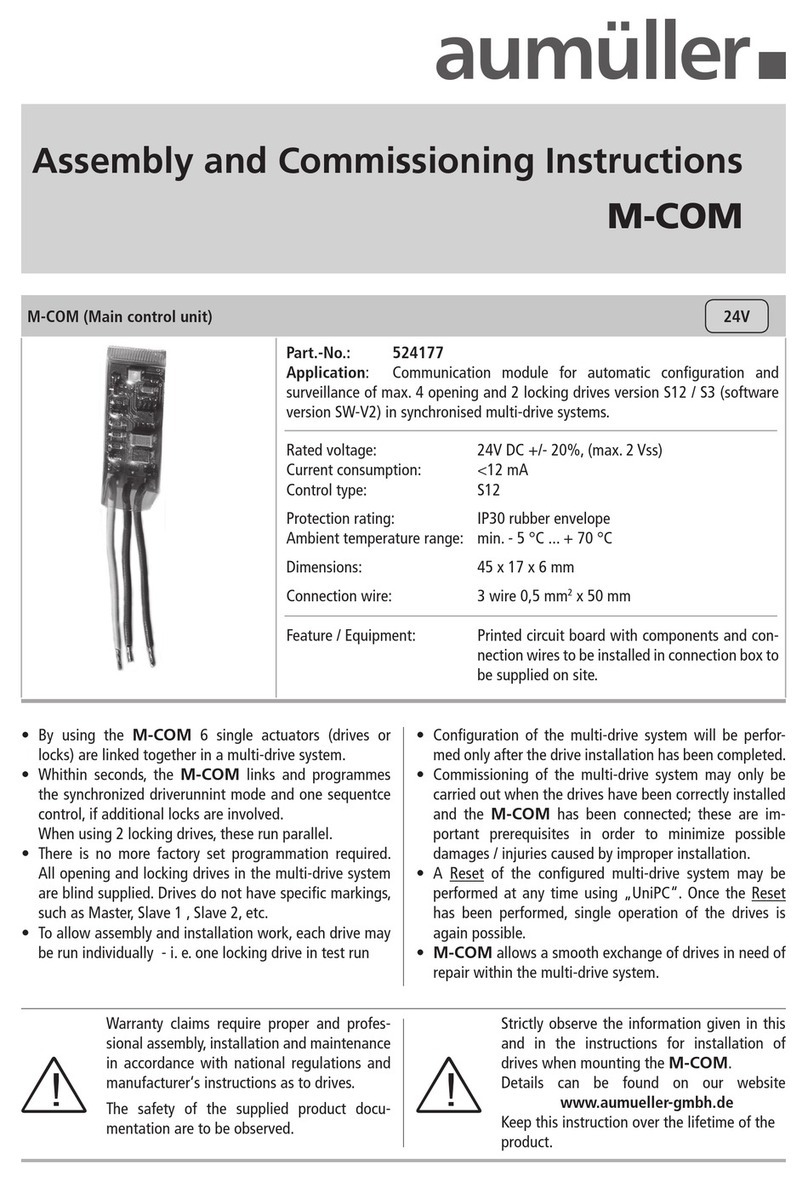
Power-Module PM = 16,1 mA
PM-Extension PME = 0,0 mA
Control-Module CM = 34,0 mA
Sensor-Module SM = 12,6 mA
Drive-Module IDM = 4,6 mA
Drive-Module DM = 5,3 mA
Drive-Module DMX = 5,3 mA
Weather-Module WM = 13,0 mA
Relay-Module RM6 = 4,2 mA
KNX-Module IM-K = 3,7 mA
Intrinsic consumption
of backup battery powerd detectors
Break-glass main unit HSE = 1,2 mA
Break-glass seccondary unit HSE-N = 0,0 mA
Optical smoke detector ORM = 0,1 mA
Wind direction sensor WRG = 7,1 mA
BUS Break-glass unit BUS-HSE = 2,8 mA
BUS Smoke detector BUS-RM = 1,0 mA


