manuals.online logo
Brands
  1. Home
  2. •
  3. Brands
  4. •
  5. Aumuller
  6. •
  7. Control Unit
  8. •
  9. Aumuller M-COM Training manual

Aumuller M-COM Training manual

!
!
M-COM (Main control unit) 24V
• By using the M-COM 6 single actuators (drives or
locks) are linked together in a multi-drive system.
• Whithin seconds, the M-COM links and programmes
the synchronized driverunnint mode and one sequentce
control, if additional locks are involved.
When using 2 locking drives, these run parallel.
• There is no more factory set programmation required.
All opening and locking drives in the multi-drive system
are blind supplied. Drives do not have specic markings,
such as Master, Slave 1 , Slave 2, etc.
• To allow assembly and installation work, each drive may
be run individually - i. e. one locking drive in test run
• Conguration of the multi-drive system will be perfor-
med only after the drive installation has been completed.
• Commissioning of the multi-drive system may only be
carried out when the drives have been correctly installed
and the M-COM has been connected; these are im-
portant prerequisites in order to minimize possible
damages / injuries caused by improper installation.
• A Reset of the congured multi-drive system may be
performed at any time using „UniPC“. Once the Reset
has been performed, single operation of the drives is
again possible.
• M-COM allows a smooth exchange of drives in need of
repair within the multi-drive system.
Warranty claims require proper and profes-
sional assembly, installation and maintenance
in accordance with national regulations and
manufacturer‘s instructions as to drives.
The safety of the supplied product docu-
mentation are to be observed.
Strictly observe the information given in this
and in the instructions for installation of
drives when mounting the M-COM.
Details can be found on our website
www.aumueller-gmbh.de
Keep this instruction over the lifetime of the
product.
Assembly and Commissioning Instructions
M-COM
Rated voltage: 24V DC +/- 20%, (max. 2 Vss)
Current consumption: <12 mA
Control type: S12
Protection rating: IP30 rubber envelope
Ambient temperature range: min. - 5 °C ... + 70 °C
Dimensions: 45 x 17 x 6 mm
Connection wire: 3 wire 0,5 mm2x 50 mm
Feature / Equipment: Printed circuit board with components and con-
nection wires to be installed in connection box to
be supplied on site.
Part.-No.: 524177
Application: Communication module for automatic conguration and
surveillance of max. 4 opening and 2 locking drives version S12 / S3 (software
version SW-V2) in synchronised multi-drive systems.
Assembly Instruction
M-COM
INSTALLATION
INSTALLATION STEP 1: INSTALLATION
¢Mount the drives according the instructions for in-
stallation the drives.
¢Connect the multi-drive system to the M-COM and to
the supply line.
Before installation make sure, that there is no
voltage applied to the supply line!
Do not connect the WH-wire of the end
module to the WH-wire of the drives!
!
Connection: multi-drive system with M-COM
1
3
BN
BU
WH
M1 M2 Mx
BN
BU
WH
2
BK
BK
OG
LED
line end module
M-COM
drives connected in a multi-drive system
max. 4 opening and 2 locking drives
plug connections site-supplied
size depends on the number of drives and
wire section
line end module
only with SHEV as a monitoring in the last box
24 V DC supply line / control unit
junction box site-supplied
M2M1 Mx
BN
BU
WH
BU
BN
WH
BU
BN
WH
BU
BN
WH
BN
BU
BK
BK
OG
+
+
-
-
M-COM
Control unit
BK = black
BN = brown
BU = blue
OG = orange
WH = white
2
NOTE NOTE
24V-drives with version S12 / S3 (soft-
(ware version SW-V2) required. In SHEV case t additionally the line end
module into the last junction box.
Assembly Instruction
M-COM
COMMISSIONING / TEST RUN / RESET / TROUBLSHOOTING
INSTALLATION STEP 2:
FIRST COMMISSIONING
¢Switch on the supply voltage (24 V DC) - in CLOSE
direction.
¢Observe the LED reaction of the M-COM.
¢LED blinks red (Factory settings).
¢LED starts blinking red / green. The communication
- to the multi-drive operation - is running.
¢LED blinks green, for each participator once. The pro-
cess is complete.
¢Compare the numer of devices with the numer of
identied participants.
¢Check the operation of the multi-drive system according
the instructions for installation the drives.
TROUBLSHOOTING:
Function of the multi-drive system does not
satisfying the requirements
TROUBLSHOOTING:
Number of participatnts was mis-identied.
¢Check wiring and the system.
¢Eliminate faults.
¢Reset the M-COM (see chapter „Reset of M-COM“).
¢If the synchronism and the control of the closing
sequence does not satisfying the requirements, contact
our Service for special programming.
3
INSTALLATION STEP 3:
TEST RUN, MALFUNCTION, TROUBLSHOOTING
¢Switch on the supply voltage (24 V DC) - in CLOSE
direction.
¢Observe the LED reaction of the M-COM.
RESET OF M-COM
¢Connect white wires (WH) of the M-COM.
¢Put the system - with M-COM - back into operation
(see chapter „First commissioning“).
¢Switch off the supply voltage (24 V DC).
¢Disconnect white wires (WH) of the M-COM.
¢Switch on the supply voltage (24 V DC) - in CLOSE
direction.
¢Observe the LED reaction of the M-COM.
¢The LED starts blinking red and lights after successful
reset permanently red until the drives are connected.
LED display
Display State
0,5s - 0,5s
blinks red (6 times)
M-COM is waiting.
continuous
lights red
until the drives are connected
M-COM is reset
(Factory settings).
LED display
Display State
3s
lights red
Factory settings
(M-COM is reset).
0,5s - 0,5s
blinks red / green (10 times)
Communication - to the multi-drive
operation - becomes set up.
0,5s - 0,5s - 3s
blinks green (X times)
X drives identied
(1 time blinks = identied one drive).
<
LED display
Display State
0,5s - 0,5s - 3s
blinks green (per drive 1 time)
System is o.k. (can be operated)
drives identied
(1 time blinks = identied one drive).
0,5s - 0,5s - 3s
blinks red (X-times)
When the number of the
learned drives does not coin-
cide with the number of drives
now recognized.
FAULT: System is NOT o.k.
X drives identied
(1 time blinks = identied one drive).
<<
AUMÜLLER AUMATIC GMBH
Gemeindewald 11
86672 Thierhaupten
Tel. +49 8271 8185-0
Fax
+49 8271 8185-250
info@aumueller-gmbh.de
www.aumueller-gmbh.de
AUMÜLLER AUMATIC GMBH
Gemeindewald 11
86672 Thierhaupten
Tel. +49 8271 8185-0
Fax
+49 8271 8185-250
info@aumueller-gmbh.de
9000003001_V2.0_KW22/16
TROUBLSHOOTING
TROUBLSHOOTING:
Exchanging a faulty drive in the multi-drive
system:
¢Switch off the supply voltage (24 V DC).
¢Disconnect the connection cable from the faulty drive.
Do not remove the M-COM.
¢Mount the new / repaired drive and connect it.
¢Switch on the supply voltage (24 V DC) - in CLOSE
direction.
¢Observe the LED reaction of the M-COM.
¢Within 10 seconds the M-COM signals „Ready for
operation“ for the congured system.
¢If the LED blinks red, an error is displayed.
¢Reset the M-COM (see chapter „Reset of M-COM“).
¢Check wiring and the system.
¢Eliminate faults.
¢Put the system - with M-COM - back into operation
(see chapter „First commissioning“) .
¢If the LED blinks red, an error is displayed.
¢Reset the M-COM (see chapter „Reset of M-COM“).
¢Check wiring and the system.
¢Eliminate faults.
¢Put the system - with M-COM - back into operation
(see chapter „First commissioning“) .
No adjustment is carried out in case of ex-
change of drives with special program-
ming (e.g. stroke, speed)!
In case of repair please order an exchange drive with the
same parameter assignment as that of the faulty drive.
!
TROUBLESHOOTING USING UNIPC
¢Connect the UniPC to the system (observe the
information given in the instructions for installation of
UniPC).
¢By UniPC determine the address of the faulty drive.
¢Individually disconnect white wires (WH) of drives,
to nd out where the fault drive is localized.
¢Switch off the supply voltage (24 V DC).
¢Disconnect and replace the faulty drive.
¢Switch on the supply voltage (24 V DC) - in CLOSE
direction.
¢Observe the LED reaction of the M-COM.
¢Within 10 seconds the M-COM signals „Ready for
operation“ for the congured system.
LED display State
0,5s - 0,5s - 3s
blinks green (per drive 1 time)
System is o.k. (can be operated)
drives identied
(1 time blinks = identied one drive).
LED display State
0,5s - 0,5s - 3s
blinks green (per drive 1 time)
System is o.k. (can be operated)
drives identied
(1 time blinks = identied one drive).
LED display State
0,5s - 0,5s - 3s
blinks red (X-times)
When the number of the
learned drives does not coin-
cide with the number of drives
now recognized.
FAULT: System is NOT o.k.
X drives identied
(1 time blinks = identied one drive).
LED display State
0,5s - 0,5s - 3s
blinks red (X-times)
When the number of the
learned drives does not coin-
cide with the number of drives
now recognized.
FAULT: System is NOT o.k.
X drives identied
(1 time blinks = identied one drive).
<
<
<
<

Other Aumuller Control Unit manuals

Aumuller EMB 7300 Installation and operation manual

Aumuller

Aumuller EMB 7300 Installation and operation manual

Aumuller EMB 7300 Series Installation and operation manual

Aumuller

Aumuller EMB 7300 Series Installation and operation manual

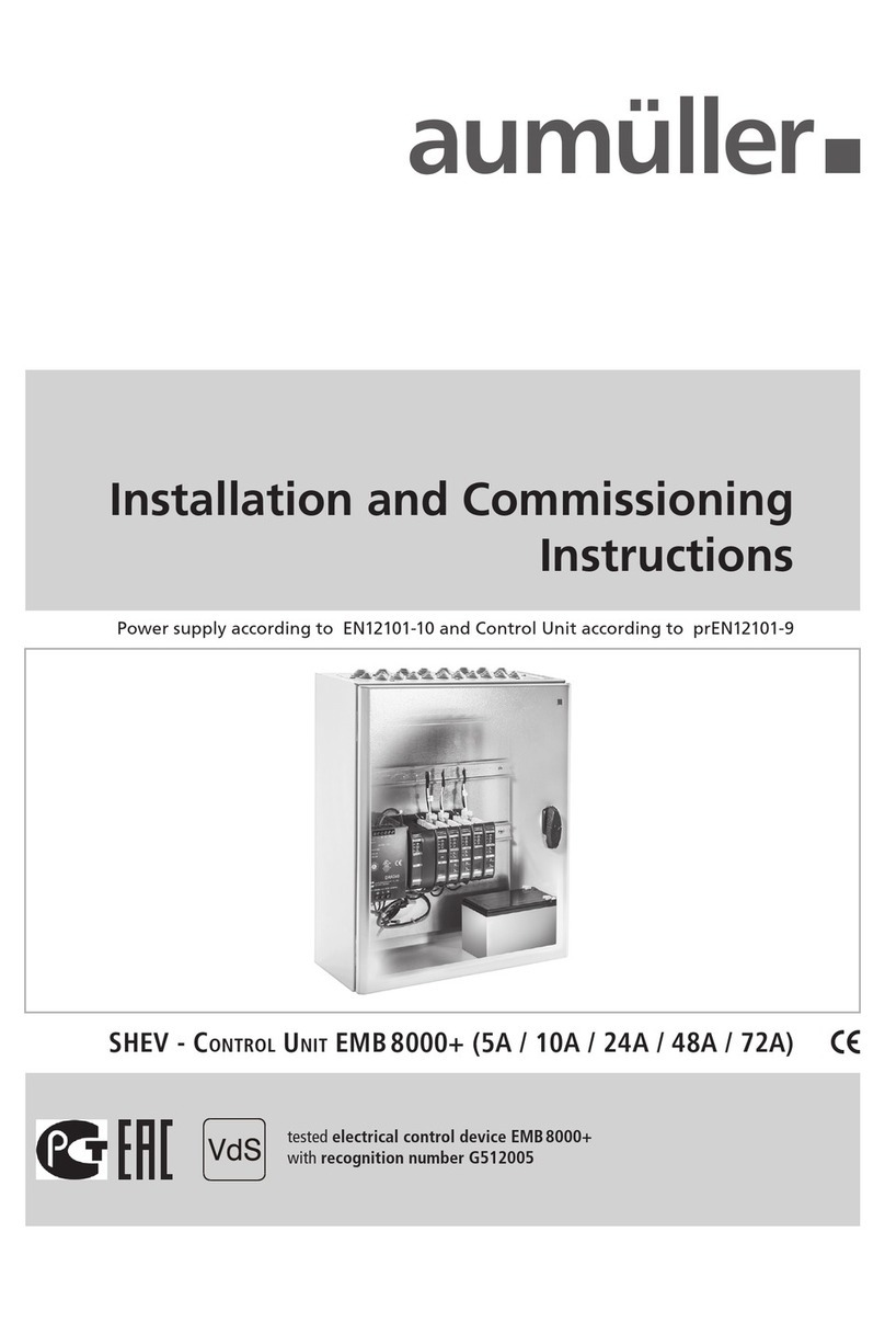
Aumuller SHEV EMB 8000+ Series Installation and operation manual

Aumuller

Aumuller SHEV EMB 8000+ Series Installation and operation manual

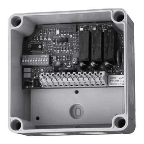
Aumuller USKM Training manual

Aumuller

Aumuller USKM Training manual

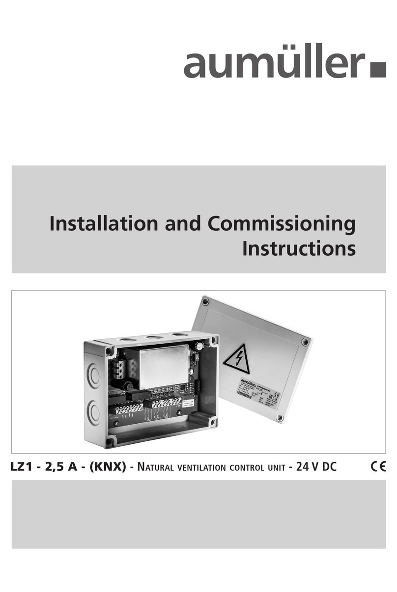
Aumuller LZ1-2,5A-KNX Installation and operation manual

Aumuller

Aumuller LZ1-2,5A-KNX Installation and operation manual

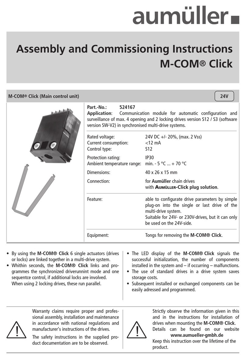
Aumuller M-COM Click Training manual

Aumuller

Aumuller M-COM Click Training manual

Aumuller M-COM Click Training manual

Aumuller

Aumuller M-COM Click Training manual

Aumuller SHEV EMB 8000+ Series Installation and operation manual

Aumuller

Aumuller SHEV EMB 8000+ Series Installation and operation manual

Popular Control Unit manuals by other brands

Technische Alternative CAN-I/O45 installation instructions

Technische Alternative

Technische Alternative CAN-I/O45 installation instructions

SEA USER 1 - 24v DG R1 manual

SEA

SEA USER 1 - 24v DG R1 manual

Advantech PCM-3524 user manual

Advantech

Advantech PCM-3524 user manual

ADLINK Technology PXI-7901 user manual

ADLINK Technology

ADLINK Technology PXI-7901 user manual

emaux COLOR TOUCH Series Installation and operation manual

emaux

emaux COLOR TOUCH Series Installation and operation manual

Tanita RA102 user manual

Tanita

Tanita RA102 user manual

Texas Instruments TPA6120A2RGY EVM user guide

Texas Instruments

Texas Instruments TPA6120A2RGY EVM user guide

Sharp NU-JC400B installation manual

Sharp

Sharp NU-JC400B installation manual

WAREMA Uniswitch ZL Operating and installation instructions

WAREMA

WAREMA Uniswitch ZL Operating and installation instructions

Helios AIR1-SM DX Installation and operating instructions

Helios

Helios AIR1-SM DX Installation and operating instructions

Microdyn Nadir Bio-Cel L-1 Technical instructions

Microdyn Nadir

Microdyn Nadir Bio-Cel L-1 Technical instructions

SIMON URMET nea 14108 manual

SIMON URMET

SIMON URMET nea 14108 manual

SEQUANS VZ120Q user manual

SEQUANS

SEQUANS VZ120Q user manual

sentlotec Pro-B3 manual

sentlotec

sentlotec Pro-B3 manual

Coelbo 1305TT Installation and operating instructions

Coelbo

Coelbo 1305TT Installation and operating instructions

Firgelli FA-SYNC-4 user manual

Firgelli

Firgelli FA-SYNC-4 user manual

Beninca DA.AXE operating instructions

Beninca

Beninca DA.AXE operating instructions

EOS EMOTEC L 09 Relay Assembly and operating instructions

EOS

EOS EMOTEC L 09 Relay Assembly and operating instructions

manuals.online logo
manuals.online logoBrands
  • About & Mission
  • Contact us
  • Privacy Policy
  • Terms and Conditions

Copyright 2025 Manuals.Online. All Rights Reserved.