auragen G5000 User manual

MAIN INSTALLATION MANUAL
FOR AN AURAGEN®INDUCTION
POWER SOURCE
Vehicle Powered
Mobile Electric Power
Models G5000, G6000D, G6000X, G8500, G8500X
Aura Systems, Inc.
2335 Alaska Avenue, El Segundo, CA. 90245
Phone: (310) 643-5300 - Fax: (310) 643-7457 - Toll Free (800) 909-AURA
Web Site: www.aurasystems.com

020530E MAN-050-200, MAIN INSTALLATION MANUAL Page
AUTOMOTIVE AURAGEN®MAIN INSTALLATION MANUAL
i
TABLE OF CONTENTS
Subject Page
Section 1 - Introduction
About this Manual.................................................................................................... 1-1
Functional Description of the AuraGen System.......................................................
.
1-1
AuraGen Induction Power Source.......................................................................
.
1-1
Electronic Control Unit (ECU) ............................................................................. 1-1
AuraGen System Specifications..........................................................................
.
1-1
Mountin
g
Kit............................................................................................................
.
1-5
Estimated Installation Time.....................................................................................
.
1-5
Recommended Tools..............................................................................................
.
1-5
AuraGen System Components................................................................................ 1-5
Mountin
g
Kit Contents.............................................................................................
.
1-5
Recommended Tools and Materials for AuraGen System Installation and Test......
.
1-5
Required Additional Installation Materials................................................................ 1-6
How to Obtain Service............................................................................................. 1-6
Returnin
g
AuraGen Components for Warranty or Service ...................................... 1-6
Section 2 - Warning and Safety Precautions
Warnin
g
s and Precautions......................................................................................
.
2-1
Exhaust Gases........................................................................................................ 2-1
General Safety Precautions..................................................................................... 2-2
Movin
g
Parts Safety................................................................................................
.
2-2
Electrical Shock....................................................................................................... 2-2
AuraGen Connection to Buildin
g
s ........................................................................... 2-2
Section 3 - General Installation Instructions for all Vehicles
Cable Routin
g
.......................................................................................................... 3-1
Connectin
g
Output Cable to Induction Power Source.............................................. 3-5
Electronic Control Unit Mountin
g
- All......................................................................
.
3-6
ECU Installation - Commercial................................................................................. 3-8
ECU Installation - Military/Offroad ..........................................................................
.
3-11
ECU Hookup Hardware........................................................................................... 3-13
AuraGen and ECU Wirin
g
Hookup.......................................................................... 3-14
Si
g
nal Harness Installation...................................................................................... 3-14
Si
g
nal Harness Connection at ECU......................................................................... 3-15
Installation of the Control Panel............................................................................... 3-16
Remote Power Strip Connector Installation.............................................................
.
3-17
Output Power Wirin
g
for AC Only - 120/240............................................................ 3-18
Hard Wired Output Power - 120/240 VAC, 20 Amp Service................................
.
3-18
Hard Wired Output Power - 120/240 VAC, 40 Amp Service................................
.
3-20
Output Power Wirin
g
for AC/DC ECU - 120 VAC and 14 or 28 VDC ..................... 3-22
Hard Wired Output Power - 20 Amp 120 VAC Service........................................ 3-22
DC Power and Ground Cable Connections - AC/DC System:.............................. 3-25
Output Power Wirin
g
for DC Only ECU - 14 or 28 VDC ......................................... 3-27
Output Power Wirin
g
for Inverter/Char
g
er System ................................................
.
3-30
Hard Wired Output Power - 120/240 VAC Service..............................................
.
3-30
DC Power and Ground for Inverter/Char
g
er System...........................................
.
3-32
Field Installation of ECU EMI/RFI Filter Kit ............................................................
.
3-33
Manual Transfer Switch - General Familiarization .................................................
.
3-36

AUTOMOTIVE AURAGEN®MAIN INSTALLATION MANUAL
020530E MAN-050-200, MAIN INSTALLATION MANUAL Page ii
TABLE OF CONTENTS
Subject Page
Section 4 - Software Installation and System Testing
S
y
stem Requirements.............................................................................................
.
4-1
About AuraEngr ECU Software...............................................................................
.
4-1
Installing AuraEngr Software .................................................................................. 4-1
Help for Installation Problems.................................................................................. 4-2
Creating a AuraEng Shortcut................................................................................... 4-2
Setting Up and Registering Your Software..............................................................
.
4-3
How to Pro
g
ram the AuraGen ECU......................................................................... 4-5
Setup of Equipment for Testing............................................................................... 4-6
Changing Vehicle Types.......................................................................................... 4-7
Usin
g
the ECU Status Monitor................................................................................. 4-7
Drivability Test......................................................................................................... 4-8
Section 5 - Installing the AuraGen into Specific Vehicles
Installation Notes..................................................................................................... Reserved
Application Catalog.................................................................................................. Reserved
Section 6 - AuraGen Troubleshooting Guide Reserved
Figures
Figure 1-1: AuraGen System Specification - AC-Only.............................................
.
1-2
Figure 1-2: AuraGen System Specification - DC and AC/DC................................... 1-3
Fi
g
ure 1-3: AuraGen S
y
stem Specification - G6000X Inverter Char
g
er (ICS).......... 1-4
Figure 1-4: AuraGen System Specification - G8500X Inverter Charger (ICS).......... 1-5
Figure 3-1: Cable Routing - Fire wall.......................................................................
.
3-1
Fi
g
ure 3-2: Cable Routin
g
- Under the Vehicle........................................................
.
3-2
Figure 3-3: Cable Routing - Access Holes............................................................... 3-2
Figure 3-4: Interconnection Diagram ......................................................................
.
3-3
Fi
g
ure 3-5: Pictorial Wirin
g
Dia
g
ram........................................................................ 3-4
Figure 3-6: Liquid Tight Conduit Fittings.................................................................. 3-5
Figure 3-7: G5000 and G6000 Power Strip Connect...............................................
.
3-5
Fi
g
ure 3-8: G8500 Power Strip Connect.................................................................. 3-6
Figure 3-9: ECU Enclosures - Splash Water Environment....................................... 3-7
Figure 3-10:ECU Enclosure - Withour Splash Water Environment.......................... 3-8
Fi
g
ure 3-11: Drill Hole for Rivnut.............................................................................
.
3-9
Figure 3-12: Using the Rivnut Installation Tool........................................................
.
3-9
Figure 3-13: Installing the Rivnut............................................................................. 3-9
Figure 3-14: ECU Mounting - Commercial............................................................... 3-11
Figure 3-15: ECU Mounting - Military/Offroad.......................................................... 3-12
Figure 3-16: Power Cable Conduit Fittings..............................................................
.
3-13
Figure 3-17: ECU Fitting Assembly. .................................. 3-13
Figure 3-18: ECU Terminal Block Connection.........................................................
.
3-14
Figure 3-19: ECU EMI/RFI Filter Connection......................................................... 3-14
Figure 3-20: ECU Signal Cable Installation.............................................................. 3-16
Figure 3-21: ECU Signal Cable Connector..............................................................
.
3-16
Fi
g
ure 3-22: Secure Si
g
nal Harness to ECU...........................................................
.
3-16
Figure 3-23: Remote Power Strip Connector........................................................... 3-17
Figure 3-24: Secure Power Connector to ECU........................................................ 3-17
Fi
g
ure 3-25: ECU Output Power / Hard Wire Connection........................................ 3-18

020530E MAN-050-200, MAIN INSTALLATION MANUAL Page
AUTOMOTIVE AURAGEN®MAIN INSTALLATION MANUAL
iii
TABLE OF CONTENTS
Subject Page
Figure 3-26: 120 /240 VAC 20 Amp Power Connection to AC Only ECU ...............
.
3-19
Figure 3-27: ECU Output Power / Hard Wire Connection........................................ 3-20
Figure 3-28: 120 VAC, 40 Amp Power Connection to AC Only ECU.......................
.
3-21
Figure 3-29: AC/DC ECU Connection Arrangement (Typical).................................. 3-22
Figure 3-30: ECU Output Power / Hard Wire Connection........................................ 3-23
Figure 3-31:120 VAC, 20 Amp Power Connection to AC/DC ECU..........................
.
3-24
Figure 3-32: ECU DC Power and Ground Terminals...............................................
.
3-25
Figure 3-33 DC Power Cable Connect at ECU........................................................ 3-25
Figure 3-34: DC Power Cable Connect at Battery...................................................
.
3-25
Figure 3-35: DC Power Cable Terminal Boot........................................................... 3-26
Figure 3-36: DC Ground Cable Connection at ECU................................................ 3-26
Figure 3-37: DC Ground Cable Connection at Battery............................................. 3-26
Figure 3-38: 14 Volt Jumper Installation..................................................................
.
3-27
Figure 3-39: DC Only Cable Installation - For Reference Only................................
.
3-28
Figure 3-40: DC Power Cable Connect at ECU....................................................... 3-28
Figure 3-41: DC Power Cable Connect at Battery...................................................
.
3-29
Figure 3-42: DCPower Cable Terminal Boot............................................................ 3-29
Figure 3-43: ECU Output Power/Hard-wire Connection........................................... 3-30
Figure 3-44: 120/240 VAC Power Connection to Inverter/Charger ECU.................. 3-31
Figure 3-45: Inverter/Charger System DC Cable Routing........................................ 3-32
Figure 3-46: Cut Red and Black Wires....................................................................
.
3-33
Figure 3-47: Insulate Ends of Red and Black Wires................................................
.
3-33
Figure 3-48: Remove Output Wires from Terminal Strip.......................................... 3-34
Figure 3-49: Install AC Output Filter Plate ..............................................................
.
3-34
Figure 3-50: Install Output Filter .............................................................................
.
3-34
Figure 3-51: Install Wires on AC Output Power Board............................................. 3-34
Figure 3-52: Install Wires on AuraGen Input Filter................................................... 3-35
Figure 3-53: Install Ferrite Filter on Signal Harness ................................................ 3-35
Figure 3-54: AC Output Reference Colors............................................................... 3-35
Figure 3-55: Manual Transfer Switch System.......................................................... 3-36
Figure 3-56: Manual Transfer Switch Features........................................................ 3-37
Figure 4-1: AuraEngr Password Dialog Box............................................................
.
4-2
Figure 4-2: AuraEngr Main Screen.......................................................................... 4-3
Figure 4-3: Configuration Dialog Box....................................................................... 4-3
Figure 4-4: Find Modem Selection........................................................................... 4-3
Figure 4-5: AuraEngr Password Tab Dialog............................................................
.
4-4
Figure 4-6: Go-On-Line Display............................................................................... 4-4
Figure 4-7: AuraEngr On-line .................................................................................. 4-4
Figure 4-8: AuraEngr Logon Dialog Box ................................................................. 4-5
Figure 4-9: AuraEngr Main Screen.......................................................................... 4-5
Figure 4-10: Configuration Dialog Box.................................................................... 4-5
Figure 4-11: AuraEngr Main Screen........................................................................
.
4-6
Figure 4-12: RegistrationDialog Box........................................................................ 4-6
Figure 4-13: AuraEngr Main Screen .......................................................................
.
4-6
Figure 4-14: AuraEngr Program Upload .................................................................
.
4-6
Figure 4-15: ECU Installation Window..................................................................... 4-7
Figure 4-16: ECU System Status Monitor................................................................ 4-7
Figure 4-17: Control Panel LED Codes - Non-Inverter/Charger Systems...............
.
4-10
Figure 4-18: Control Panel LED Codes - Inverter/Charger Systems....................... 4-11

AUTOMOTIVE AURAGEN®MAIN INSTALLATION MANUAL
020530E MAN-050-200, MAIN INSTALLATION MANUAL Page
ABOUT THIS MANUAL
This manual provides detailed step-by-step
instructions for installing an AuraGen system
into a select series of vehicles. The instructions
use photographs and line drawings to clarify
each step. Study this manual carefully and
comply with all warnings and cautions. Correct
installation of the AuraGen system will result in
longer unit life, better performance and safer
operation.
This manual contains numerous safety warnings
and cautions. These relate to personal safety
as well as to the safety of the vehicle and the
AuraGen system. A detailed overview of the
warnings and safety precautions is given in
Section 2 of this manual.
In addition, there are specific warnings and
cautions that appear throughout the manual
wherever they are appropriate. Be sure to read
Section 2 of this manual thoroughly before
beginning the installation procedure.
FUNCTIONAL DESCRIPTION OF
SYSTEM
Overall System Description
The AuraGen Induction Power Source System
uses the rotating energy from a vehicle engine
to produce commercial grade AC electrical
power whenever the vehicle engine is running.
The AuraGen produces a substantial amount of
power at normal/near engine idle. When the
power loads increase, the vehicle idle speed is
automatically increased as necessary by adjust-
ing the engine throttle. 5000 watts of power out-
put requires only about 1,300 engine RPM in a
typical V-8 gasoline engine and between 650
and 900 RPM for most diesel applications. Tem-
perature sensors located inside the AuraGen
and ECU will automatically shutdown the sys-
tem in the unlikely event of component overheat-
ing.
AuraGen Induction Power Source
The source of electrical power is the AuraGen
Induction Power Source. This device resembles
an oversized vehicle alternator. It can be
mounted to the engine and mechanically ro-
tated (driven) by a serpentine belt coupled to
the crankshaft. Other drive options available in-
clude direct coupled via hydraulic motion and
via a driveshaft from a PTO located on a trans-
mission.
The AuraGen incorporates a speed sensor for
sensing the rotor RPM, and, as noted earlier, a
temperature sensor for thermal protection. Un-
like a conventional vehicle alternator, the Au-
raGen does not contain built in diodes to con-
vert the generated AC to DC. Instead, the AC
output is supplied through a four-wire power
cable to the ECU.
The Induction Power Sources are offered in dif-
ferent models, each having specific power out-
put capabilities.
AuraGen Electronic Control Unit (ECU)
The ECU is usually located in the rear of the
vehicle.
The AuraGen generates AC power which is sup-
plied to the Electronic Control Unit (ECU). The
ECU converts this to a DC voltage first, then
inverts this, then filters the power to achieve120/
240 volt single phase output.
AuraGen Systems Specifications
The AuraGen and ECUs are offered in various
performance configurations. These differences
are exhibited in the following specification
tables.
1-1

020530E MAN-050-200, MAIN INSTALLATION MANUAL Page
AUTOMOTIVE AURAGEN®MAIN INSTALLATION MANUAL
Figure 3-3: AuraGen System Specification - G6000X Inverter Charger (ICS)
1-4
AURAGEN PRODUCTS
STANDBY POWER (20 MINUTES) 6000 WATTS 6000 WATTS 6000 WATTS 6000 WATTS
CONTINUOUS POWER 5000 WATTS 5000 WATTS 5000 WATTS 5000 WATTS
AC POWER (CONTINUOUS) 5000 WATTS 5000 WATTS 5000 WATTS 5000 WATTS
AC STANDBY (20 MINUTES) 6000 WATTS 6000 WATTS 6000 WATTS 6000 WATTS
AC PEAK (2 SECONDS) 7200 WATTS 7200 WATTS 7200 WATTS 7200 WATTS
AC VOLTAGE 120 VAC 240 VAC 120 VAC 240 VAC
AC CURRENT (CONTINUOUS) 42 AMPS 21 AMPS 42 AMPS 21 AMPS
AC POWER 2500 WATTS 2500 WATTS 4000 WATTS 4000 WATTS
AC PEAK (2 SECONDS) 3000 WATTS 3000 WATTS 6000 WATTS 6000 WATTS
AC VOLTAGE 120 VAC 240 VAC 120 VAC 240 VAC
AC CURRENT 21 AMPS 11 AMPS 33 AMPS 16 AMPS
ENGINE ON-TO-OFF-TO-ON
TRANSITION
BATTERY DRAW/AC ON/NO LOAD
BATTERY DRAW/AC OFF
BATTERY DRAW
DC POWER
DC VOLTAGE
DC CURRENT
TOTAL HARMONIC DISTORTION
FREQUENCY STABILITY
VOLTAGE REGULATION
VEHICLE BATTERY
ENGINE BELT
POWER-TAKE-OFF
HYDRAULIC MOTOR
GENERATOR
ECU
GENERATOR
ECU
GENERATOR
ECU
GAS ENGINES
DIESEL ENGINES
AUTO START
INTERFERENCE FILTER MODULE
POWER STRIP
TRANSFER SWITCH
UP TO 3500 WATTS
28 VDC
125 AMPS
UP TO 1750 WATTS
125 AMPS
14 VDC
S
P
E
C
I
F
I
C
A
T
I
O
N
S
INVERTER CHARGER (ICS)
G6000X 12 VDC G6000X 24 VDC
YES
YES
YES
24 VDC
12.16"DX6.4"W
20.75"LX13.5"WX8.52"H
65 LBS.
64 LBS.
-40 ”F TO +200 ”F
SEAMLESS
LESS THAN .01 AMPS
APPROX. 100 AMPS PER KW
LESS THAN 2.5%
50/60 –0.15 HZ
1.5%
1200 TO 6000 RPM
750 TO 3600 RPM
YES
YES
YES
TOTAL POWER
AC OUTPUT IN
GENERATOR
MODE/ENGINE ON
AC OUTPUT IN
BATTERY
MODE/ENGINE OFF
DC OUTPUT
AC POWER QUALITY
DRIVE OPTIONS
DIMENSIONS
WEIGHT
OPERATIONAL
AMBIENT
OPERATIONAL
ENGINE SPEED
OPTIONAL FEATURES
10 AMPS NOMINAL
12 VDC
12.16"DX6.4"W
20.75"LX13.5"WX8.52"H
65 LBS.
64 LBS.
-40 ”F TO +200 ”F
-40 ”F TO +120 ”F
N/A
YES
YES
YES
N/A
YES
YES
YES
-40 ”F TO +120 ”F
1200 TO 6000 RPM
750 TO 3600 RPM
SEAMLESS
8 AMPS NOMINAL
LESS THAN .01 AMPS
APPROX. 50 AMPS PER KW
LESS THAN 2.5%
50/60 –0.15 HZ
1.5%

020530E MAN-050-200, MAIN INSTALLATION MANUAL Page
AUTOMOTIVE AURAGEN®MAIN INSTALLATION MANUAL
MOUNTING KIT CONTENTS
•AuraGen Mounting Bracket
•Supplemental brackets
•AuraGen Pulley Assembly
•Necessary serpentine or V belt(s)
•Throttle control & mounting hardware
•Misc. hoses, idlers, tensioners and fasten-
ers to install brackets.
RECOMMENDED AND REQUIRED
TOOLS AND MATERIALS FOR
AURAGEN SYSTEM INSTALLATION
AND TEST
Recommended:
√S.A.E. wrenches –7/16" through 1-1/4 "
√Metric wrenches –8 mm through 19 mm
√1/4", 3/8" and 1/2" ratchets with exten-
sions
√S.A.E. sockets –7/16" through 3/4"
√Metric sockets –8 mm through 19 mm
√Hose clamp removal tool or pliers
√Power steering pump pulley puller
√Serpentine and/or V belt tensioner tool
√Phillips head screwdrivers
√Wire cutters (large and small)
√Knife
√Hacksaw
√Straight edge (24")
√Torque wrench (10-100 ft-lbs.)
√Crimping tool
√Rivnut tool
√S.A.E. and metric Allen wrench set
√Tape measure
√Volt-ohm meter
√Drill, drill bit, and hole saw set
√Scribe
√Fender covers
√Misc. Items:
Marker , drain pan for engine coolant,
drop light
MOUNTING KIT
The mounting kit allows proper installation and
mounting of the AuraGen to the vehicle engine.
When installed properly, the serpentine belt will
line up with all idlers and tensioners. The
mounting kit is always vehicle and engine
specific. You must have the correct mounting
kit for the particular make, model year and
engine configuration of the vehicle into which
the AuraGen system is to be installed. Each
mounting kit contains a mounting bracket to
which the AuraGen is attached and related
mounting hardware.
Due to possible OEM midyear design varia-
tions, attempts to install an AuraGen kit on chas-
sis models and engine configurations not de-
fined in the AuraGen Induction Power Source
Catalog, or the presence of aftermarket equip-
ment, incompatibilities may be experienced
with the AuraGen mounting kit and/or informa-
tion provided in this manual. Although Aura will
assist the installer to resolve these types of con-
ditions, it cannot be held responsible for addi-
tional installer labor, time, and costs associated
with such variations.
ESTIMATED INSTALLATION TIME
An experienced two person crew will need
between two and four hours for a standard
installation that includes a remote power strip.
AURAGEN SYSTEM
COMPONENTS
•AuraGen Power Induction Source
•AuraGen Control Panel
•AuraGen Electronic Control Unit/Inverter
Charger System (ECU/ICS)
•Mounting hardware for the ECU/ICS
•AuraGen Signal Harness
•Power cable (Not Included with mounting kit.
See Required Additional Material).
1-6
AUTOMOTIVE AURAGEN®MAIN INSTALLATION MANUAL
020530E MAN-050-200, MAIN INSTALLATION MANUAL Page
REQUIRED ADDITIONAL INSTAL-
LATION MATERIALS
Caution! All electrical wires, plugs, outlets,
and switches used with the AuraGen sys-
tem must be in accordance with the UL
1248 standard.
Required installation materials are;
•Power Cable, 1/2" liquid tight shielded metal
conduit with four (4) #10 AWG multi-strand
conductors. The recommended wire insula-
tion is type THNN (high temperature). Use
different colors (i.e. red, black, white and
green).
•Automotive grade wire loom (1/2", 3/4" and
1.0") temperature rating of 205°C
•Cable ties, different lengths
•Loctite 242 (blue)
•#6 flanged spade terminals (Thomas & Betts
RC10-6FL)
•Electrical tape
•Electrical outlets; 120 VAC-20 amp (GFI rec-
ommended), 240 VAC-20 amp
•Optional: 3/4" and 1.0" rubber insulated
metal clamps (Edel clamps).
•Optional: Remote Power Strip
.
1-7
HOW TO OBTAIN SERVICE
The AuraGen system can only be serviced by
certified AuraGen technicians working for au-
thorized AuraGen distributors, OEM’s, or deal-
ers.
The AuraGen and ECU are not designed to be
field repairable. These components are in-
tended to be removed and replaced as a whole.
RETURNING AURAGEN
COMPONENT(S) FOR WARRANTY
OR SERVICE
In the unlikely event that you need to return an
AuraGen Inductive Power Source, ECU, or
bracket to Aura Systems for service, the
following steps must be performed or the
component(s) will not be accepted by Aura.
1. Complete a Customer Concern Field Prob-
lem Report (CCFPR) and e-mail or fax (310-
643-7457) it to AuraGen Product Support.
AuraGen Customer Service will contact you
with a Return Material Authorization (RMA)
number. If this is a warranty claim, Customer
Service will ask whether you wish to have a
replacement shipped, or a credit applied to
your account.
2. Insert a copy of the CCFPR into the ship-
ping container.
3. Return the component(s) in an appropriate
container (original packing preferred). If you
do not have a appropriate container, one will
be provided.
4. Include the RMA number on the packing slip
and on the outside of the container.
5. Note: Aura Systems does not pay for expe-
dited delivery of warranty or service com-
ponents.
Required Tools:
√Simplex Load Bank, 0-10,000 watts
√ECU Interface Box
√Windows 95/98 PC (laptop recom-
mended)
√AuraEngr Interface Software

AUTOMOTIVE AURAGEN®MAIN INSTALLATION MANUAL
020530E MAN-050-200, MAIN INSTALLATION MANUAL Page
WARNINGS AND SAFETY
PRECAUTIONS:
Before installing the AuraGen system, read this
manual to become familiar with the equipment
and its features. Operation of the equipment
can be achieved safely and efficiently when the
unit is properly installed and maintained. Most
accidents happen because people fail to fol-
low fundamental rules and precautions.
The following symbols are included in this
manual to advise of any potential dangerous
conditions to the operator, service personnel
from the vehicle wiring harness prior to per-
forming welding repairs on a vehicle. The
AuraGen input fuse, input ground wire as
well as the temperature sensor and RPM
sensor leads need to be disconnected if
welding repairs on a vehicle are necessary.
♦DO NOT run electrical and fuel lines through
the same compartment openings.
♦Have a fire extinguisher on hand.
♦Properly maintain the extinguisher and be-
come familiar with its use.
Extinguishers rated ABC by the NFPA are
appropriate for all applications.
♦Consult the local fire department for the cor-
rect type of extinguisher for different appli-
cations.
VEHICLE EXHAUST GASES ARE
DEADLY!
♦Do not test or operate the AuraGen System
in an enclosed area. Always ensure there
is proper ventilation when testing, operat-
ing and/or installing the AuraGen system.
♦Never sleep in the vehicle with the vehicle
running unless the vehicle is equipped with
an operational carbon monoxide detector
that shuts the engine off if CO levels are too
high.
♦Provide adequate ventilation to expel dis-
charged gases. Inspect the vehicle’s ex-
haust system for leaks according to the ve-
hicle maintenance schedule. Ensure that
the exhaust manifolds are secure and not
warped. Do not use the exhaust gases to
heat the work area.
This symbol is used to warn of im-
mediate hazard which will result in
severe personal injury or product
damage.
This symbol is used to warn of an
electrical hazard or unsafe practice
which may result in personal injury,
product damage or property dam-
age.
This symbol is used to warn of a
mechanical hazard or unsafe prac-
tice which can result in severe per-
sonal injury or death.
For the Equipment:
♦DO NOT engage or disengage the AuraGen
or ECU output connector(s) while the vehicle
engine is running.
♦DO NOT lay any component on caustic
chemical liquids or compounds.
♦Keep outlet covers down while not in use to
prevent any debris from becoming lodged
within the contacts.
♦DO NOT tie electrical wires to any fuel lines.
♦Please disconnect the vehicle battery(s), and
any OEM Electronic Control Module (ECM)
2-1
020530E MAN-050-200, MAIN INSTALLATION MANUAL Page
AUTOMOTIVE AURAGEN®MAIN INSTALLATION MANUAL
ELECTRICAL SHOCK CAN CAUSE
SEVERE PERSONAL INJURY OR
DEATH:
♦Disconnect the vehicle battery before work-
ing on or around the engine or AuraGen sys-
tem.
♦Use rubber insulating mats or dry wood plat-
forms over floors that are metal or concrete
when working around electrical equipment.
♦Do not wear damp clothing (especially wet
shoes), or allow skin surfaces to be damp
when working withelectrical equipment.
♦Use extreme caution when working with live
electrical components.
♦Follow all state and local electrical codes.
♦Tag any open circuit to prevent accidental
closure.
DO NOT CONNECT THE AURAGEN
SYSTEM DIRECTLY TO THE ELEC-
TRICAL SYSTEM OF ANY BUILD-
ING.
♦Differing voltages between the AuraGen sys-
tem and the utility line can create a potential
for electrocution and property damage, in-
cluding the ECU.
♦Connect the AuraGen system only through
an approved device and only after the
building’s main switch is open.
♦Consult a licensed electrician for all electri-
cal connection matters.
♦Provide proper exhaust ventilation to the ex-
terior of the building or facility for any vehicle
parked in an enclosed area.
GENERAL SAFETY PRECAUTIONS:
♦Hot coolant under pressure can cause se-
vere personal injury. DO NOT open a radia-
tor pressure cap while the engine running.
Stop the engine and allow to cool before very
carefully bleeding the system of pressure.
♦DO NOT operate power equipment when
mentally or physically fatigued, or after con-
sumption of alcohol or any drug that makes
the operation of equipment unsafe.
MOVING PARTS CAN CAUSE SE-
VERE PERSONAL INJURY OR
DEATH:
♦Keep hands, loose clothing and long hair
away from all moving parts.
♦Make sure that fasteners on the AuraGen
are secure. Keep supports and clamps tight
and keep guards in position over fans, drive
belts, etc.
♦Do not wear loose clothing while working on
the AuraGen. Loose clothing and jewelry can
be caught in moving parts.
♦Jewelry can short out electrical contacts and
cause shock or burning.
♦Do not make any adjustments while the en-
gine is running. Use extreme caution around
hot exhaust manifolds, ignition wires, mov-
ing parts, etc.
2-2
020530E MAN-050-200, MAIN INSTALLATION MANUAL Page
AUTOMOTIVE AURAGEN®MAIN INSTALLATION MANUAL
Cable Routing
The AuraGen Signal Harness connects the ECU
to the Throttle Control, Control Panel, and the
AuraGen’s Temperature and RPM sensors. All
of the system connectors are brought together
into a common cable under the hood. The Power
Cable and the Signal Harness should be
separated by roughly 5 inches, and routed to
the Electronic Control Unit (ECU). Some parts
of the Signal Harness may require routing into
the driver’s compartment or dashboard. See
Figures 3-1 through 3-3 for guidelines on routing
cables under the vehicle.
See Figure 3-5 for a general pictorial wiring
diagram. See Figure 3-4 for a component
interconnect diagram.
Specific routing methods are left to the
discretion and judgment of the installer and the
wishes of the individual vehicle owner.
However the following guidelines must be
strictly followed to prevent damage to equipment
or injury to personnel.
♦Do not route any cable near movingparts or
where it will be subject to friction or exces-
sive vibration.
♦Place all wiring in wire loom to provide pro-
tection from environment and abrasion.
♦Secure wire bundles to the vehicle every 12
to 18 inches.
♦Do not leave any bare wires exposed.
♦Maintain roughly 5 inches between the Power
Cable and the Signal Harness.
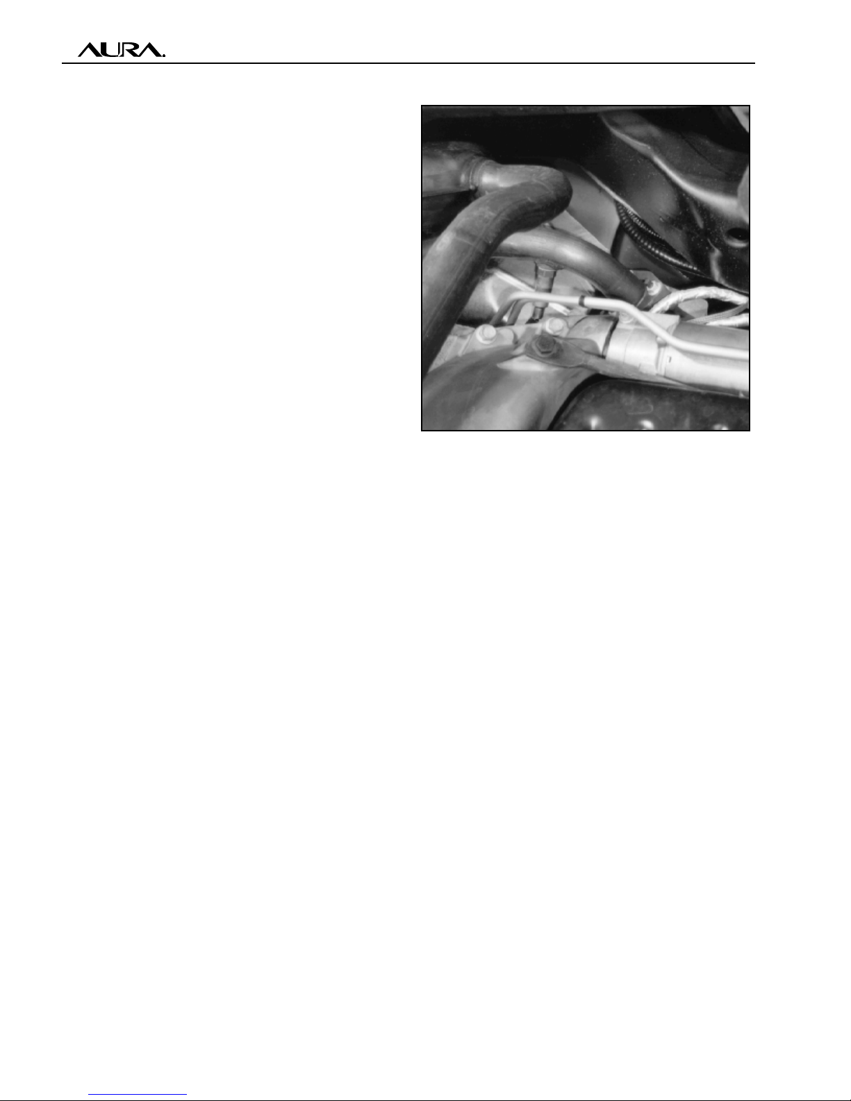
Figure 3-1: Signal Harness and Power
Cables are routed under the vehicle. Take
care to keep cables at least 6" away from
exhaust components, as shown.
♦ If too close to the exhaust system/compo-
nent, wrap heat tape on the Signal Harness
and/or Power Cable to protect them from
damage.
3-1

AUTOMOTIVE AURAGEN®MAIN INSTALLATION MANUAL
020530E MAN-050-200, MAIN INSTALLATION MANUAL Page
Figure 3-2: Route cables to rear area of
vehicle, keeping them clear of anything that
might subject them to damage by abrasion,
flexing or heat.
Do not route any cable near sharp or hot parts.
In particular, keep cables at least 6" away from
exhaust manifolds, mufflers or other exhaust
components.
Figure 3-3: Drill a hole in the underside of the
vehicle near the place where the ECU is to be
located and route the Signal Harness and Power
Cable through it, as shown. Seal hole(s) with
grommets or clear silicone after the cables are
secured.
3-2
020530E MAN-050-200, MAIN INSTALLATION MANUAL Page
AUTOMOTIVE AURAGEN®MAIN INSTALLATION MANUAL
3-3
Figure 3-4: Interconnection Diagram of the AuraGen Systems
Duke
Parkin
g
Brake/
Neutral Switch
Remote Start
Fused
+12 VDC
Switched
RPM
Te m p
Power
Conduit
AuraGen
Generator
Electronic
Control Unit
(ECU)
Power Strip
(optional)
Control Panel
Throttle Control Unit
Hook to
Throttle
Linkage
+
-
-
+
(Yellow Wire)
(Purple Wire)
Power Cable
Output Power
• Hardware
• Power Strip (Optional)
Mechanical or Electronic
IdleControl Unit
Induction Power
Source
AUTOMOTIVE AURAGEN®MAIN INSTALLATION MANUAL
020530E MAN-050-200, MAIN INSTALLATION MANUAL Page 3-4
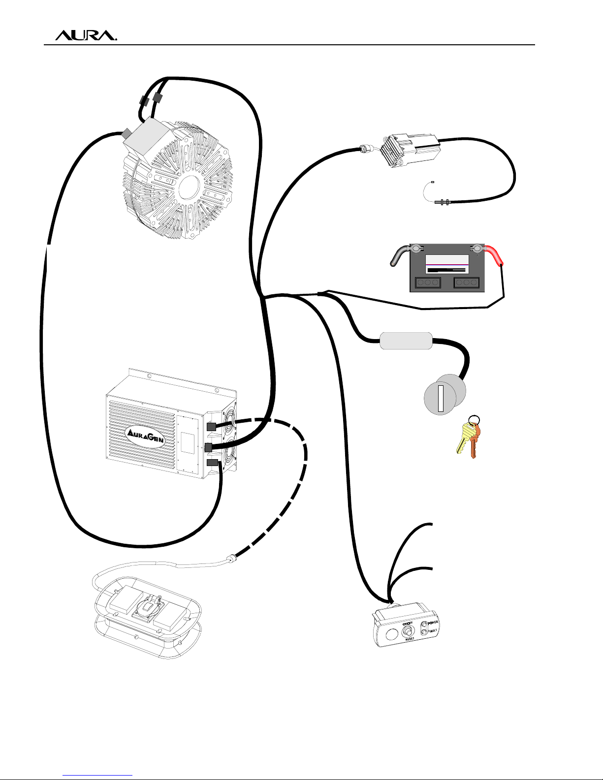
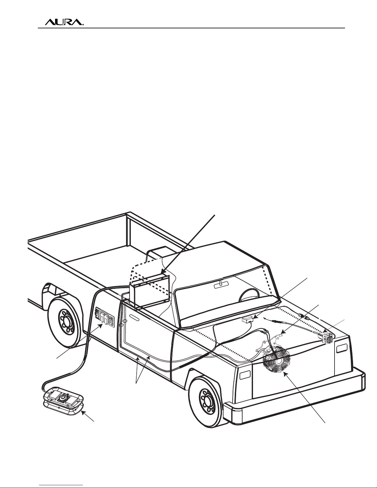
CONTROL AND POWER
CABLES ROUTED UNDER
VEHICLE TO REAR-MOUNTED
ELECTRONIC CONTROL UNIT
REMOTE POWER STRIP
(OPTIONAL)
RECEPTACLE
OUTLET BOX
AURAGEN MOBILE
GENERATOR
THROTTLE CONTROL
(LOCATION MAY VARY)
MOUNTING BRACKET
(ENGINE AND VEHICLE
SPECIFIC)
CONTROL UNIT
ON/OFF - STATUS LEDs
(USUALLY LOCATED UNDER DASH)
ELECTRONIC CONTROL UNIT
Figure 3-5: Pictorial Wiring Diagram of a “Typical Installation”
IDLE CONTROL
(LOCATION MAY VARY)
AURAGEN INDUCTION POWER SOURCE

020530E MAN-050-200, MAIN INSTALLATION MANUAL Page
AUTOMOTIVE AURAGEN®MAIN INSTALLATION MANUAL
Connecting Power Output Cable
to the AuraGen
Note: Use only high quality #10 AWG multi-
strand copper wire (with THNN or equivalent
insulation) to connect the ECU to the AuraGen.
Solid wire will fatigue and eventually break. Do
not attempt to connect short pieces of wires to-
gether, use a one piece length of cable (cut to
size).
To connect the four-wire power output cable to
the AuraGen, perform the following steps:
1. Use a straight edge to mark the circumfer-
ence of the flexible conduit.
2. Using a hacksaw,cut approximately six
inches of the conduit off to expose the four
wires inside. Note: When sawing the con-
duit, take care not to cut or damage the wire
insulation encased inside.
3. Slide the nut (B) of the liquid tight connector
over the four wires and onto the flexible con-
duit.
4. Slide seal ring (C) of the liquid tight connec-
tor over the four wires and screw it into the
flexible conduit.
5. Mount the coupler (D) into the hole on the
side of the AuraGen terminal box.
6. Secure the coupler (D) to terminal box with
the serrated nut (E) with o-ring, as shown in
Figure 3-6 and 3-7.
7. Slide the wires extending from the conduit
into the AuraGen terminal by passing the
wires through the coupler (D).
8. Connect the conduit to the AuraGen by
threading the nut (B) on the conduit to the
coupler (D) on the AuraGen.
Note: Use care when tightening conduit nut
(E). Do not pinch or nick temperature sen-
sor wire the AuraGen will not be operational
if sensor wire is damaged.
9. Route the wires to their respective terminals
while ensuring a maximum amount of ex-
cess wire while allowing for proper closure
of the terminal box. Strip one-fourth (1/4") of
insulation from ends of all four wires; apply
#10 flanged spade terminals (Thomas Betts
RC10-6FL) to each end of wire using a
crimping tool.
10. For the model G5000 and G6000 series,
connect all four wire terminal lugs to termi-
nal strip inside terminal box according to the
colors shown in Figure 3-7.
11. Torque the screws to 15 in-lbs.
12. Reinstall terminal box cover to top of the
AuraGen.
3-5
Figure 3-6: Liquid Tight Conduit Fitting
ECA
BD
Figure 3-7: G5000 and G6000 Series
Terminal Box Connections
AUTOMOTIVE AURAGEN®MAIN INSTALLATION MANUAL
020530E MAN-050-200, MAIN INSTALLATION MANUAL Page
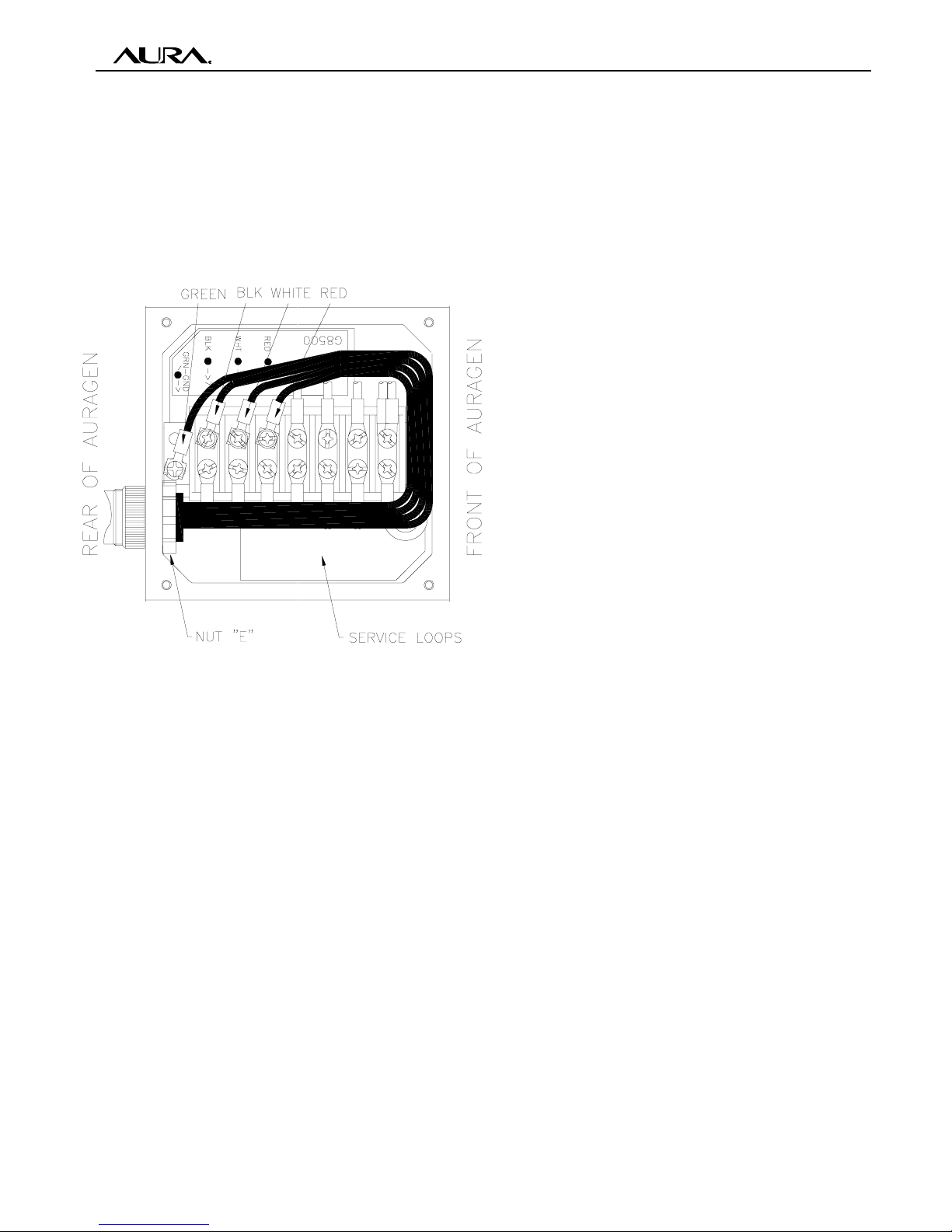
13. For the G8500 model, connect all four wire
terminal lugs to terminal strip inside termi-
nal box according to the colors shown in Fig-
ure 3-8.
14. Torque the screws to 15 in-lbs.
15. Reinstall terminal box cover to top of Au-
raGen.
3-6
Figure 3-8: G8500 Series Terminal Box
Connections
Electronic Control Unit (ECU)
Mounting - All
Caution! If the ECU requires any field modi-
fications, perform those modifications prior
to mounting.
The ECU must be mounted in a location that
will provide adequate ambient air ventilation for
cooling. If the ECU is not adequately ventilated,
the unit will overheat, produce less than full rated
power, andeventually will shut down. The
maxmum ambient air temperature, whether the
ECU is enclosed or in the shade, is 120ºF,
measured at the ECU cooling fan inlet.
Always locate the ECU where it will not be sub-
ject to excessive heat, physical damage, or
road debris/splash.
Note: The ECU requires a minimum of 6 inches
of clearance on the air intake and exhaust. Many
mounting locations are possible, such as in the
rear of a van or the bed of a pickup. When
mounted in the bed of a pickup, it is recom-
mended that the ECU be installed on the wall of
the bed just behind the cab. However, this is
not an absolute requirement.
The following are rules for ECU installation that
regard operating temperature and environmen-
tal protection. These instructional rules are rec-
ommended to prevent ECU shut down due to
overheating.
1. The ECU has to operate at an ambient tem-
perature not to exceed 120ºF, measured
at the ECU cooling fan air inlet, whether in-
stalled in an enclosure or in the open air.
2. The preferred location of the compartment
is in a shaded area. Exposure to sun ra-
diation can add hundreds of Watts to the
total heat balance of the unit.
3. The compartment must be ventilated.
4. Locate the ECU in the shaded part of the
enclosure away from any heat source.
5. If possible, mount the ECU on a vertical
panel of the compartment See Figure 3-9.
6. Do not mount the ECU with the air exhaust
facing the forward motion of the vehicle.
This causes backpressure of airflow.
7. Enclosure Inlet Air Panel:
Install louvers (or perforated plate) in the
suction air panel of the enclosure. This
panel faces the two ECU cooling fans. The
airflow area of the louvers have to have a
surface area of around 30 square inches.
This will allow cool air to enter the ECU fans
to ventilate the compartment. “Louvered
Vent”Model 282387, supplied by Sea-Fit,
are suggested. Two of these louvers are
needed (one on top of the other) as each
has about a 13.3 square inch vent area.
020530E MAN-050-200, MAIN INSTALLATION MANUAL Page
AUTOMOTIVE AURAGEN®MAIN INSTALLATION MANUAL
3-7
8. Ensure that the louvers are not positioned
such that water/mud splash from the wheels
would cause moisture to enter the compart-
ment. When splashing of water is sus-
pected, position the ECU as in Figure 3-9,
otherwise install it as in Figure 3-10.
9. Compartment Air Outlet Panel:
9.1. Two fans, 100 C.F.M. each, are nec-
essary for proper ventilation of the en-
closure. An A/C or D/C voltage fan can
be utilized for this purpose.
9.2. In moderate climates not exceeding
100ºF ambient temperature, two lou-
vers (similar to the inlet air) instead of
the fans may be used.
10. Locate the fans as close as possible to the
ECU exhaust air area. This will ensure ef-
ficient removal of hot air from the compart-
ment.
11. Do not mount the exhaust fans facing the
forward motion of the vehicle. This causes
backpressure of airflow. See Figures 3-9
and 3-10.
12. Ensure that the fans are not located such
that water/mud splash from the wheels
would cause moisture to enter the compart-
ment.
13. Additional benefit can be achieved by re-
ducing the heat radiation from the asphalt
to the lower compartment panel. This can
be accomplished by either of the following
methods.
13.1. Installing an insulation material on the
floor of the compartment.
13.2. Using a heat shield (reflect foil) on
the external lower panel. On the bot-
tom of the compartment, find the low
point and drill a hole for L.P.D (Low
Point Drain) to prevent water accumu-
lation. The size of the hole (or holes)
should be approximately 1/2".
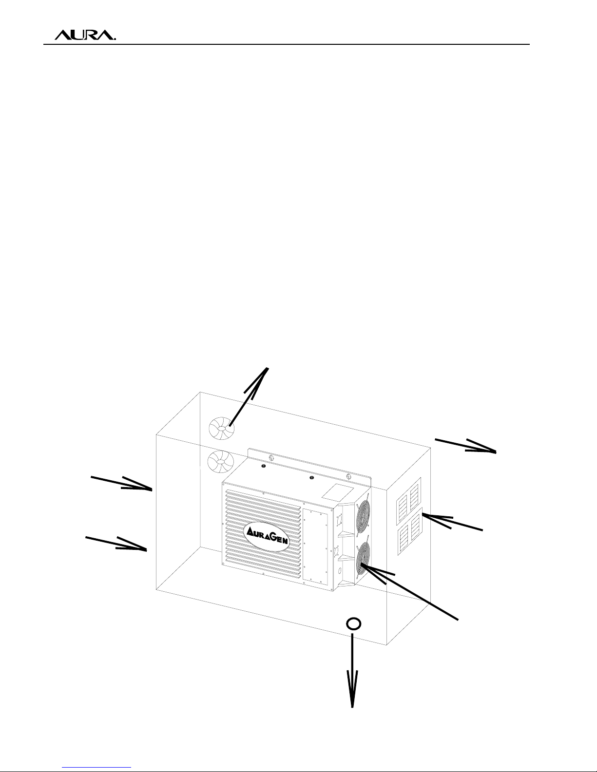
SPLASH WATER
FORWARD DIRECTION
AIR IN
AIR OUT
L.P.D.
120°F MAX. OPERATING
AIR TEMPERATURE MEA-
SURED AT ECU INLET
Figure 3-9: ECU Compartment - Spash Water Environment
AUTOMOTIVE AURAGEN®MAIN INSTALLATION MANUAL
020530E MAN-050-200, MAIN INSTALLATION MANUAL Page
ECU Installation - Commercial
(See the following section for
military and offroad mounting)
Note: Before drilling any holes, be sure that the
area immediately behind the panel you are drill-
ing into is clear of any obstructions (fuel tank,
fuel lines, brake lines or wiring).
Note: The ECU mounting hardware is pack-
aged inside the ECU.
Note: The location within a vehicle into which
the ECU is to be mounted may vary, even among
the same make and model. For these reasons,
most of the details regarding mounting and lo-
cating the ECU are left to the judgment of the
installer and the wishes of the vehicle owner.
As a typical example, the guidelines shown in
this section illustrate the installation of the ECU
into the bed of a pickup truck. The same steps
will apply to any ECU installation, only the spe-
cific location will vary.
To gain access to the mounting hardware, re-
move the access cover from the ECU.
1. Place the ECU squarely against the flat in-
side bed of the pickup, and using a scribe
or sharp pencil, mark the locations of the
four mounting holes.
2. Move the ECU out of the way, and using a
scribe or sharp pencil, mark the locations
of the two cable access holes (in the floor of
the pickup bed or bed wall). Ensure there is
access for both cables to route to ECU with-
out binding or interfering with vehicle move-
ment.
3. Center punch and drill the two 1 to 1 1/4 inch
diameter access holes into the bed wall (or
bed floor) for the power cable and signal
Harness.
4. From underneath the vehicle, feed one end
of the power cable (1/2”conduit) through
one hole.
5. Route the signal harness cable through the
second hole in the pickup bed and route to
ECU area.
6. Reposition ECU over previously marked
mounting location and ensure adequate
room for routing of the signal harness and
power cable. Move ECU out of the way.
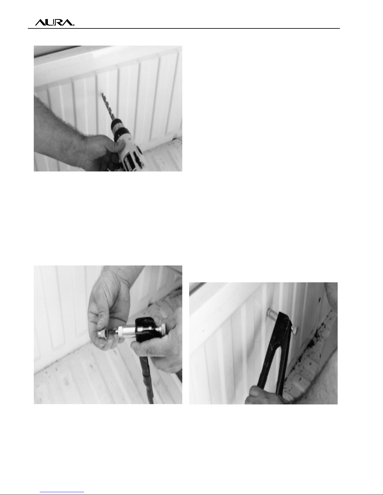
7. For Rivnuts; center punch, and with a 17/
32”(.5312) drill bit, drill four mounting holes
into the bed wall as shown in Figure 3-11.
8. For 3/8" bolts and nuts; center punch, and
with a 0.406" drill bit, drill four mounting holes
into the bed wall as shown in Figure 3-11.
3-8
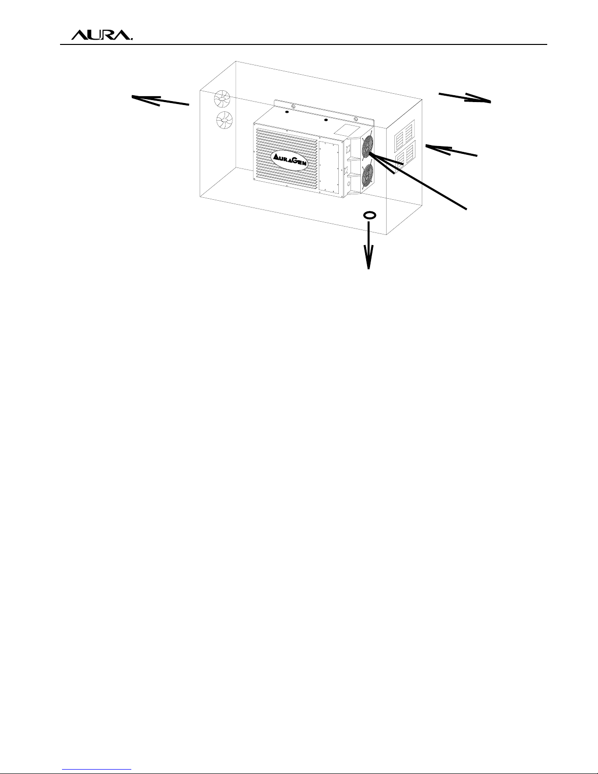
Figure 3-10: ECU Compartment - Without Spash Water Environment
AIR OUT
L.P.D.
AIR IN
FORWARD DIRECTION
120°F MAX. OPERATING
AIR TEMPERATURE MEA-
SURED AT ECU INLET
020530E MAN-050-200, MAIN INSTALLATION MANUAL Page
AUTOMOTIVE AURAGEN®MAIN INSTALLATION MANUAL
Note: Proper function of the AuraGen sys-
tem requires the ECU case to be grounded
to the chassis. Whether mounting the ECU
with Rivnuts, or nuts and washers, removal
of debris, paint, or other coatings from
around both sides of the mounting holes is
required.
9. Place a Rivnut (F/N 4) onto the insertion tool
and insert the Rivnut into one of the four holes
that were drilled in the pickup bed. It may be
necessary to add a 1/2" washer between
the Rivnut and the wall to provide sufficient
area for the Rivnut to grasp. See Figures 3-
12 and 3-13.
10. Swage the Rivnut into the hole by applying
firm pressure to the installation tool.
11. Repeat steps 8 and 9 until all four (4) mount-
ing holes have Rivnuts installed.
Note: Adequate pressure must be used to
prevent the Rivnuts from loosening and spin-
ning inside the holes. See Figure 3-13.
Some ECU’s are supplied with 3/8" bolts,
3/8" washers, and Ny-lock nuts in place of
the Rivnuts and shoulder bolts.
Figure 3-11: Drill hole for Rivnut™
Figure 3-12: Installing Rivnut Onto Tool Figure 3-13: Installing Rivnut
3-9
AUTOMOTIVE AURAGEN®MAIN INSTALLATION MANUAL
020530E MAN-050-200, MAIN INSTALLATION MANUAL Page
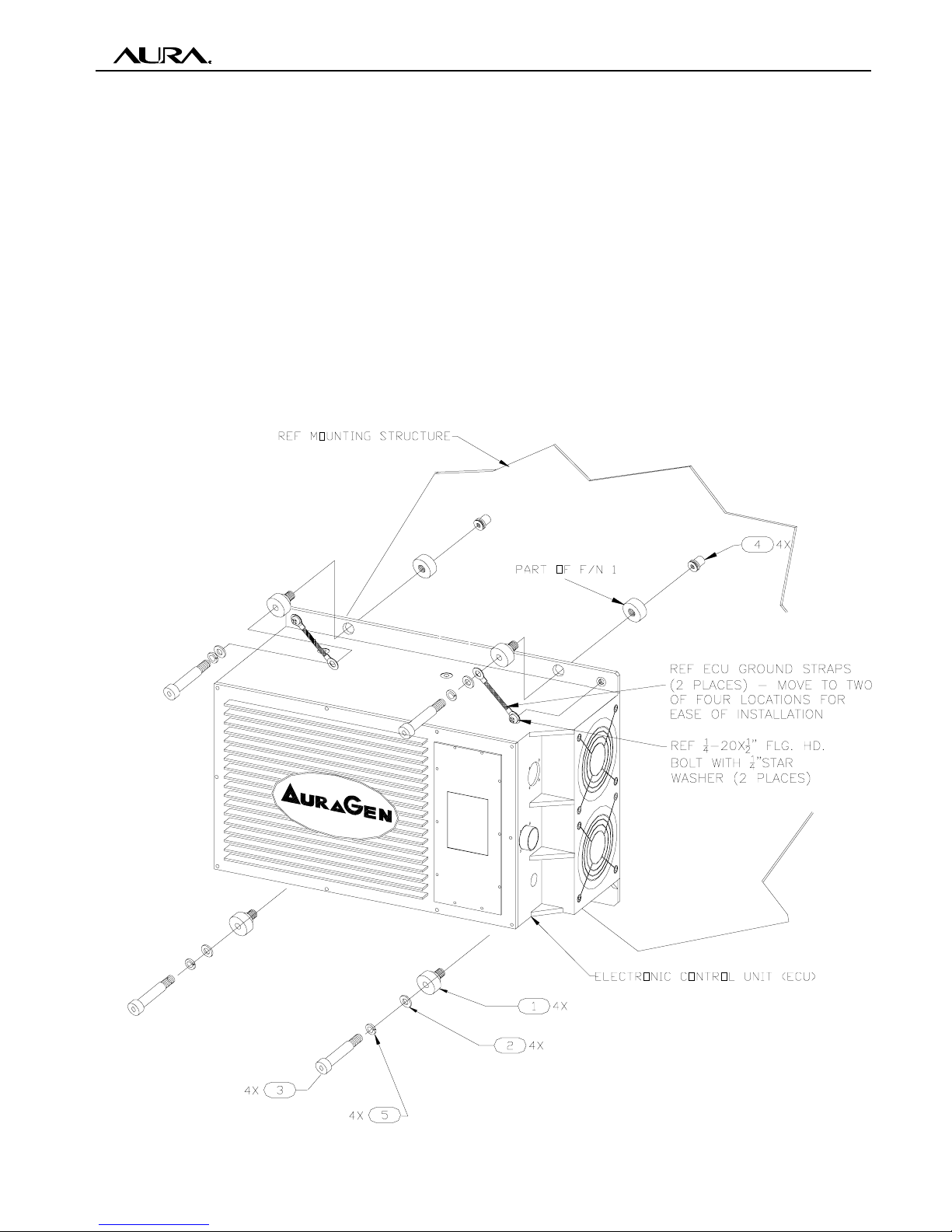
12. Install the four rubber shock mounts
(F/N 1) on the ECU. See Figure 3-14.
13. Place ECU over the mounting holes and
secure to the pickup bed using four (4) 3/
8x1 1/2" shoulder bolts (F/N 3), with 3/8"
lock washers (F/N 5), and 3/8" flat washers
(F/N 2). See Figure 3-14.
Note: The ECU has two ground straps at-
tached to it that must be added to the two
adjacent ECU mount bolts. To provide
3-10
Figure 3-14: ECU Mounting - Commercial
ease of installation, move the straps to any
of four attachment locations on the ECU
case. If the straps are relocated, torque the
1/4-20 bolts to 49-55 in-lbs.
CAUTION! Failure to ground the ECU case
to the chassis can cause system failures.
14. Add the ground strap lugs to the selected
ECU mount bolts .
15. Torque all of the 1/4" ECU mount bolts to
9-11 ft-lbs.
This manual suits for next models
4
Table of contents
Popular Portable Generator manuals by other brands

Briggs & Stratton
Briggs & Stratton 40375 Operator's manual

DEVA Broadcast
DEVA Broadcast DB9000-STC Quick user guide

Master
Master MGH10000C OWNER'S OPERATION AND INSTALLATION MANUAL

Powermate
Powermate Coleman PMC606500 user manual

Accton Technology
Accton Technology RPU150W Quick installation guide

Generac Power Systems
Generac Power Systems 005723-0 GP Series owner's manual


