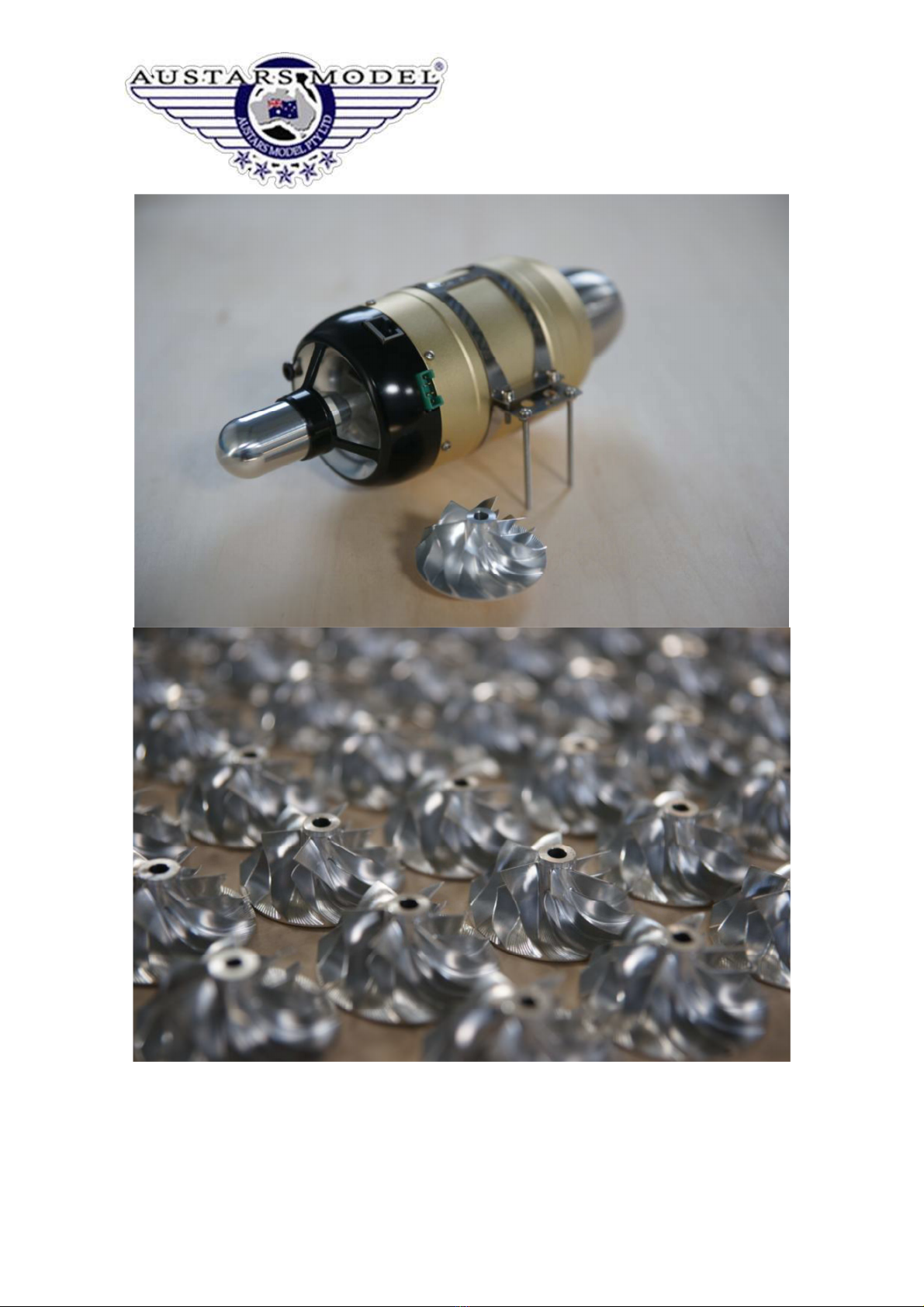
AUSTAR ACE 60 User manual

Page 1
ACE 60/120 Turbine Engine
Manual v1
21 Oct 2016

Page 2
Engine Specifications
Engine: ACE 120
Diameter: 100mm
Length: 262mm
Weight: 1400g
RPM Range: 36,000 - 125,000
Thru t: 12Kg
Maximum con umption: 320ml/min
Fuel Type: Kero ene/Die el/Jet A1
Lubrication: 5% Mobil Jet oil
Maintenance: 25Hr
Receiver Power: 5-8.4V (5S Nimh or 2S Life or 2S Lipo)
Power upply: 9.9-11.1V (3S Life or 3S Lipo)
Engine: ACE 60
Diameter: 84 mm
Length: 232 mm
Weight: 820 g
RPM Range: 50,000 - 160,000
Thru t: 6 Kg
Maximum con umption: 200 ml/min
Fuel Type: Kero ene/Die el/Jet A1
Lubrication: 5% Mobil Jet oil
Maintenance: 25Hr
Receiver Power: 5-8.4V (5S Nimh or 2S Life or 2S Lipo)
Power upply: 9.9-11.1V (3S Life or 3S Lipo)

Page 3
Safety – Rea before operating engine
Danger: Jet engine exhau t can et fire to flammable material uch a dry gra , fabric,
fuel, wood, etc. En ure your model i well protected from the jet exhau t and keep all
flammable material away from the exhau t of the engine. Do not u e the engine
where fire ban exi t.
Danger: Turbine rotate at very high rpm. In ca e of failure or inge tion of foreign
object , part can be ejected from the engine, cau ing injury or death. DO NOT tand
directly be ide the engine while tarting or running.
Danger: Do NOT modify the engine in any way. Thi could lead to failure of the engine
rotor and injury or death.
Danger: Engine emit fume which are not breathable. Only run the engine in a well
ventilated pace.
Warning: Engine ha high peed rotating part . Keep finger well clear of engine inlet
and outlet while connected to power upply.
Warning: Jet engine inlet ha high uction. Loo e object can be drawn in leading to
failure of the engine. Keep hand clear of the engine inlet a finger can be ucked into
the engine. Protect your engine with a creen (FOD creen).
Warning: Jet engine are very noi y during operation. Wear hearing protection when
operating the engine.
Warning: Engine will be hot during and after operation. The rear part of the engine
and the exhau t can reach temperature up to 700 C. Keep clear.

Page 4

Page 5
Preparing the Engine for use
Connect the fuel supply to the engine as shown below. Use a hopper tank to prevent
bubbles reaching the engine. Use 4mm fuel hose (supplied) for connections. Make sure no
air can enter the fuel lines as this may cause a flame out.
Fuel pump connections. Ensure the Anti-bubble loop stays in place as shown.

Page 6
Connect the cable to the engine and ECU a hown below.
ECU (FADEC) and GSU (Data Terminal)
Engine connections to ECU Battery, Rx and GSU connections to ECU

Page 7
Cable identification
Engine to ECU cable (power) Engine to ECU cable (sensors)
Battery and Fuel Pump to ECU cable RX (throttle) to ECU cable
Use a 3S (9.9 to 11.1V) battery, either LiFe or LiPo. Capacity should be at least 2200mAH.

Page 8
Operation
If you are inexperienced with turbojet engines, it is recommended to install the engine on a
stable test platform, and perform a number of start-up operations to get used to and check
the equipment, turbojet engine, fuel circuit, fuel filter, anti-bubble tank. When happy, then
transfer to the model aircraft. This allows you to perform operations in a secure environment
and become familiar with the engine’s performance.
For the first start or any time the fuel tube to the engine is empty, use the “TEST PUMP”
function within the “TEST” menu on the GSU to prime the fuel lines up to the engine (see
part 6.1 of GSU section).
Warning: disconnect the fuel line from the engine and collect the fuel in a container.
Do not flood fuel into the engine or a “hot start” can occur with flames coming from
the exhaust.
Use the GSU to “teach” the ECU the radio signal from your system (See part 2 of the GSU
section).
Futaba remote control must be set to reverse throttle signal, JR & Spektrum throttle normal.
To start the engine:
1. Set trim to low, throttle to low.
2. Power up Tx then Rx.
3. Set trim to high.
4. Push throttle to high, then return to idle.
When the throttle is high, the starter motor will turn, then return the throttle to the minimum.
At this time, the engine will automatically enter the ignition starting procedure.
Once the engine has stabilised, the GSU will display “Running” and you will have throttle
control over the engine.
To Stop the engine, place throttle stick to low and trim to low. The engine will stop, and the
starter motor will turn the engine to cool it down below 80 C. This is to protect the bearings
from excessive heat soak. The cooldown sequence will stop automatically and may take a
couple minutes. Do not switch off the Rx until the cooldown sequence is finished.
If the trim is in the minimum position and the throttle stick is pushed the maximum, the motor
will also rotate, but the throttle will not enter the start sequence when the throttle is at
minimum. This feature can be used to manually cool the engine or clear excess fuel from
the engine if it becomes flooded.

Page 9
In cold weather, the diesel or kerosene becomes viscous. If ignition is not prompt, or
temperature rise after ignition is slow, slightly increase "pump voltage" (see section on
GSU).
The first time the engine is started when new or new installation, you must slowly increase
the throttle after the start to the maximum speed so, the ECU can learn the maximum speed
of the pump power value.

Page 10
Engine Care an Maintenance
After 25 hours of use, the engine needs to be returned to the factory for maintenance. The
main tasks are replacement of bearings, inspection of parts, cleaning of oil lines,
replacement of internal filter elements, removal of carbon deposits, re-balancing, re-
commissioning, ECU data reset. When returning to factory for maintenance, include the
entire electronic system with the engine.
In case of crash damage, return the engine to the factory for repair.
When removing the engine or the fuel pump, it is necessary to connect the fuel nozzle with a
small section of tubing and close the fuel pipe to avoid any impurity entering the engine or
the fuel pump. If even a very small impurity enters the engine it may cause the fuel line to
block up or make the pump gear failure, or a flameout.
On any new installation, you must carefully clean the fuel tank, fuel pump outlet must be
installed oil filter, make sure the fuel lines are clear of any dust or metal particles.
Ensure the power connection to the ECU is not reversed. If any electrical plug is found to be
bad, replace immediately - intermittent power supply is also likely to cause ECU failure.
Engine cooling after the flight directly affects the life of the bearing, allow the engine to
complete its cool down sequence after every flight before removing power.
The keys to affect the life of the turbojet: overheating, heavy fall, ultra-extreme use. After
any accidental flameout, run the cooling manually - set trim low and throttle high to run the
starter motor.
If the engine suffers a heavy fall, return engine to the factory to re-balance. If any foreign
body is sucked in, resulting in blade damage, it is recommended to return to the factory to
re-balance, otherwise the bearing life will be seriously shortened.
Regularly check and clean the fuel filter.
After starting the engine, push the throttle to maximum to check for any air bubbles, as these
can cause a flameout in flight.
The engine should not expel any flames during startup. In the case that the fuel solenoid
valves become damaged or worn (eg by grit in the fuel) then fuel may pool in the engine
while refueling and cause a fire on startup.
Always close the manual ball valve in the fuel line when refueling, to avoid this possibility.
Do not attempt to start the engine if it becomes flooded with fuel, as this will cause a fire.

Page 11
Ensure the inside of the model plane is clear of any foreign or loose objects that could be
sucked into the engine – this will damage or destroy the engine.
Install a mesh cover (FOD guard) over the inlet of the engine to protect it from loose items.
Always range check your model with the engine running before flying. Do not fly if there is
any interference.
Do not use screws to plug the fuel lines on the anti-bubble tank as these can leak air into the
system. Use a proper fuel tube plug.
This manual suits for next models
1
Table of contents
Popular Engine manuals by other brands

Graco
Graco Monark Instructions-parts list

Predator Engines
Predator Engines 69731 quick start guide

jolly motor
jolly motor FCHS1 instructions

Briggs & Stratton
Briggs & Stratton 400000 Professional Series Operator's manual

Siemens
Siemens SIMOTICS GP series operating instructions

Briggs & Stratton
Briggs & Stratton 215800 Series Illustrated parts list

Volvo Penta
Volvo Penta IPS 350 Operator's manual

Generac Power Systems
Generac Power Systems GTV-990 Engine parts manual

wsm
wsm V3307-DI-T-E2B Workshop manual

Northern Lights
Northern Lights OL1276 Operator's manual

Siemens
Siemens Geared motors-Planetary gear instructions

Kohler
Kohler Courage SH265 Service manual