Simple Motors Kit 13 User manual

Assembly instructions for kit #13 1
This is not aLego® product even if it contains Lego® bricks and plates. Allwarranties provided by Simple Motors.
LEGO® is atrademark ofthe LEGO Group ofcompanies which does not sponsor, authorize or endorse this product.
All rights reserved. 2013 Simple Motors, LLC ♦www.simplemotor.com ♦
Assembly Instructions: Kit #13
Advanced QuikLock Reed Switch Motor
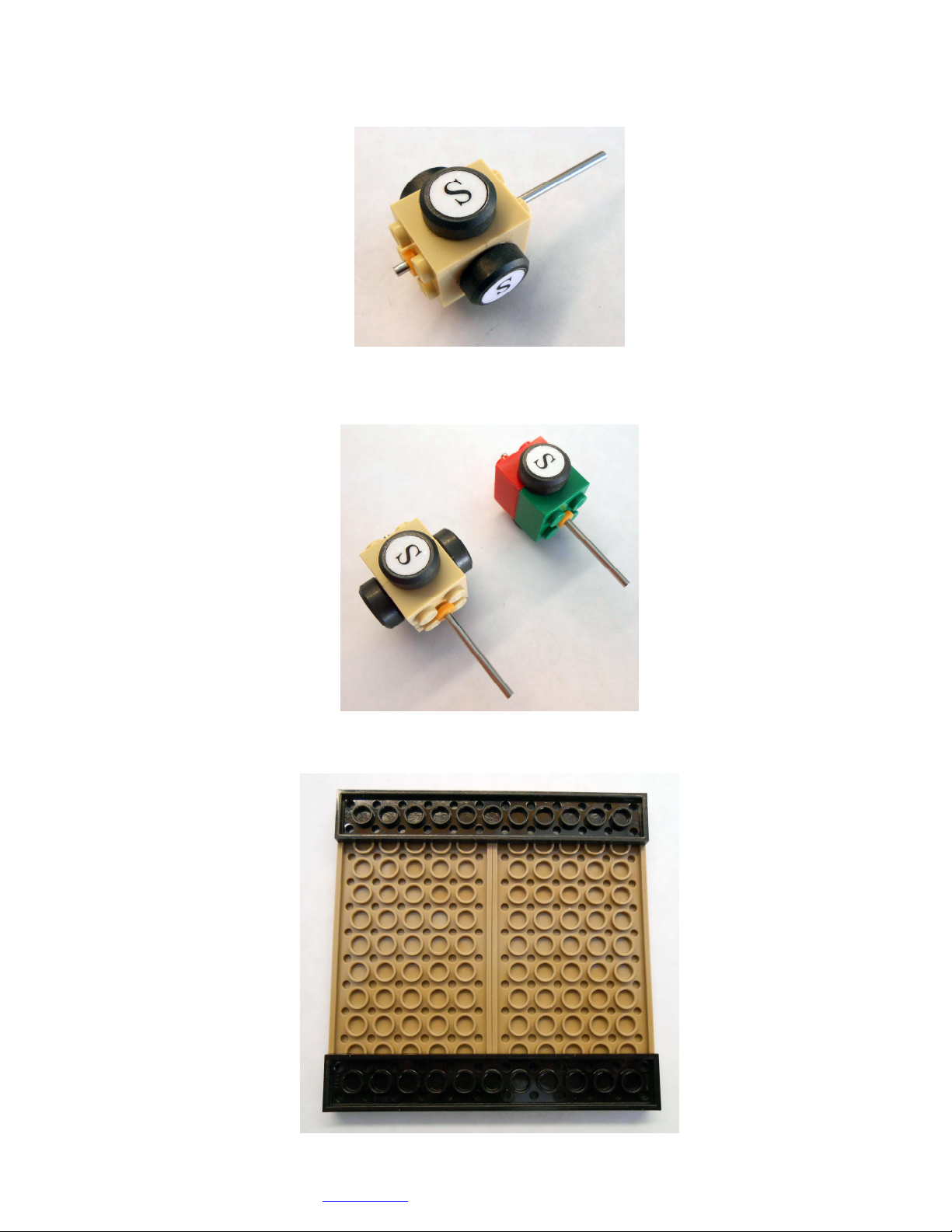
1. Glue together two 2x2 rotor pieces as shown*. Pay attention to their alignment.

Assembly instructions for kit #13 2
This is not aLego® product even if it contains Lego® bricks and plates. All warranties provided by Simple Motors.
LEGO® is atrademark ofthe LEGO Group ofcompanies which does not sponsor, authorize or endorse this product.
All rights reserved. 2013 Simple Motors, LLC ♦www.simplemotor.com ♦
2. Insert the motor shaft through the holes. Short end of the shaft should stick out about 1/8”
(3 mm) above the surface of the knobs.
3. Add plastic sleeves (washers) to both ends of the shaft. They fit tightly and require some
effort. You may put the sleeve on the table and push the shaft in with the negative end of
the battery. Leave a small gap so the sleeves are slightly above the surface of the knobs.
If you notice the burrs on the plastic sleeves remove them with a sharp knife.
>
4. Glue magnets to the rotor with the letter ‘S’ facing outside (or dimple facing inside
depending on magnet marking).
Assembly instructions for kit #13 3
This is not aLego® product even if it contains Lego® bricks and plates. All warranties provided by Simple Motors.
LEGO® is atrademark ofthe LEGO Group ofcompanies which does not sponsor, authorize or endorse this product.
All rights reserved. 2013 Simple Motors, LLC ♦www.simplemotor.com ♦
5. If you want your rotor look better, you may cut out the white glossy round labels that are
provided and paste them to the magnets. It is recommended to use regular white glue or a
glue stick on the labels for better results. This step is optional and may be done after you
finish your motor.
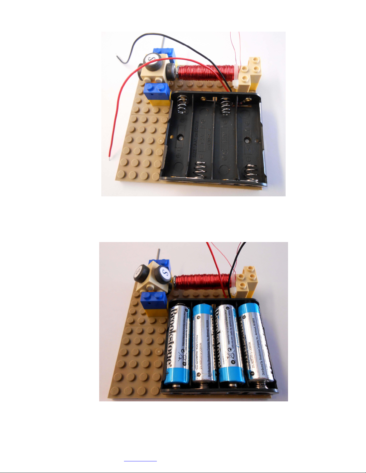
6. Make the second rotor with two magnets if you plan to compare them during your
experiments. This step is also optional and may be done later.
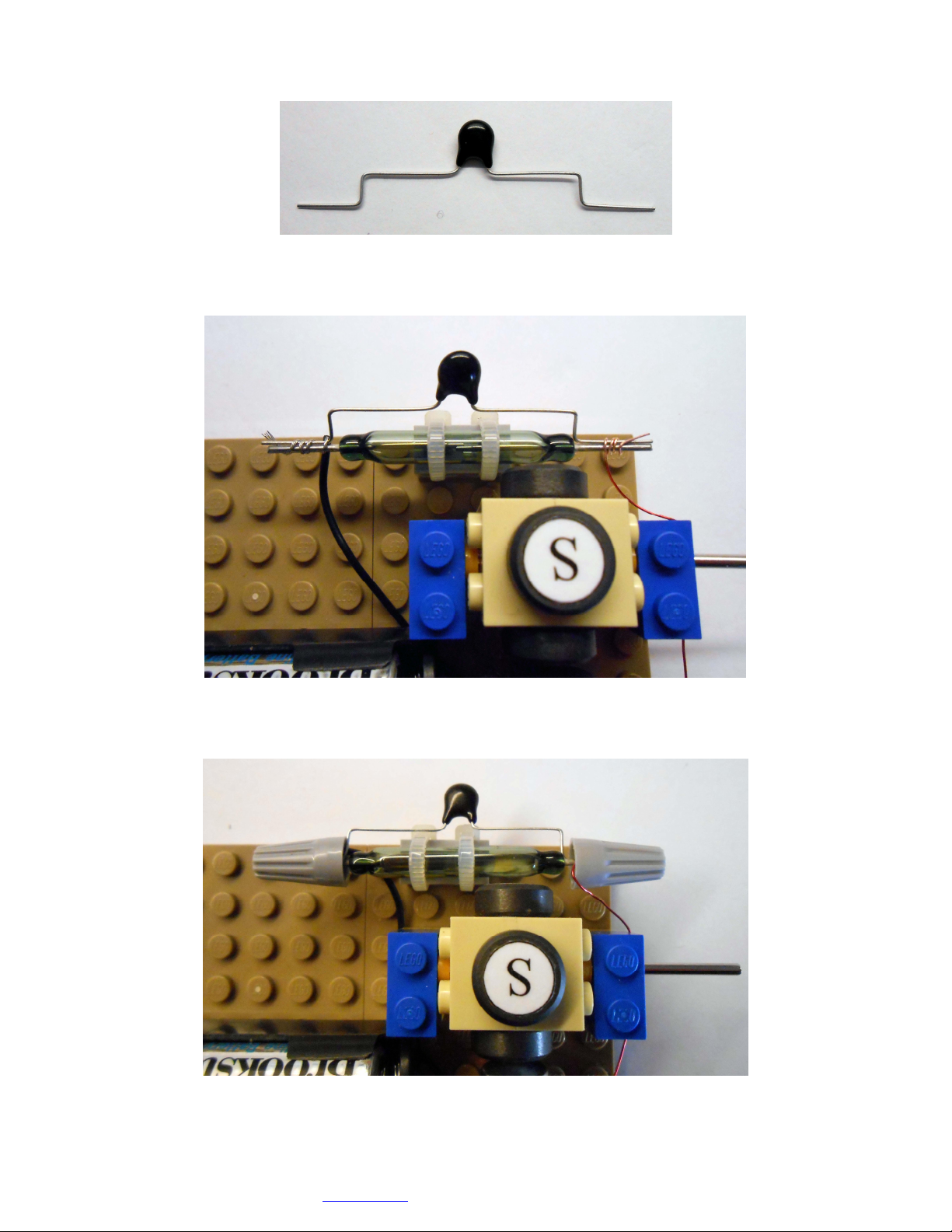
7. Assemble the motor base plate.

Assembly instructions for kit #13 4
This is not aLego® product even if it contains Lego® bricks and plates. All warranties provided by Simple Motors.
LEGO® is atrademark ofthe LEGO Group ofcompanies which does not sponsor, authorize or endorse this product.
All rights reserved. 2013 Simple Motors, LLC ♦www.simplemotor.com ♦
8. Assemble rotor on the base plate. Try to spin it by hand. If it does not spin freely you might
need to squeeze blue bricks slightly together to push plastic shaft sleeves in. There should
be a tiny gap between sleeves and inner sides of the bricks with holes.
We strongly recommend lubricating the shaft ends where they contact blue bricks. It allows
the motor to run smoother and faster. You may use a drop of oil from your car dipstick,
WD-40, or even vegetable oil.
9. Slide the 1x2 brick with two holes on the electromagnet core to the mark as shown.
If the brick is loose you may use super glue to prevent it from sliding while making the
electromagnet.
The position of the brick is important. It defines the length of the electromagnet. If it is too
long it will not fit; if it is too short the motor will be less powerful or will not work at all.
Mark on the core should be OK but you may find more precise position by checking it on the
board as shown below.
Spin the rotor and make sure that none of the magnets hits the electromagnet!

Assembly instructions for kit #13 5
This is not aLego® product even if it contains Lego® bricks and plates. All warranties provided by Simple Motors.
LEGO® is atrademark ofthe LEGO Group ofcompanies which does not sponsor, authorize or endorse this product.
All rights reserved. 2013 Simple Motors, LLC ♦www.simplemotor.com ♦
10.Measure at least 5” (13 cm) of the wire and fold it.
11.Tape the folded end and wind all the wire in one rotational direction (either clockwise or
counterclockwise) moving back and forth along the core. All spool wire should be used.

Assembly instructions for kit #13 6
This is not aLego® product even if it contains Lego® bricks and plates. All warranties provided by Simple Motors.
LEGO® is atrademark ofthe LEGO Group ofcompanies which does not sponsor, authorize or endorse this product.
All rights reserved. 2013 Simple Motors, LLC ♦www.simplemotor.com ♦
12.When there is about 5” (13 cm) of wire left, secure it with a cable tie.
13.Remove the insulation from the wire tips with fine sandpaper (included) or a sharp knife.
14.Assemble electromagnet on the base plate.
Assembly instructions for kit #13 7
This is not aLego® product even if it contains Lego® bricks and plates. All warranties provided by Simple Motors.
LEGO® is atrademark ofthe LEGO Group ofcompanies which does not sponsor, authorize or endorse this product.
All rights reserved. 2013 Simple Motors, LLC ♦www.simplemotor.com ♦
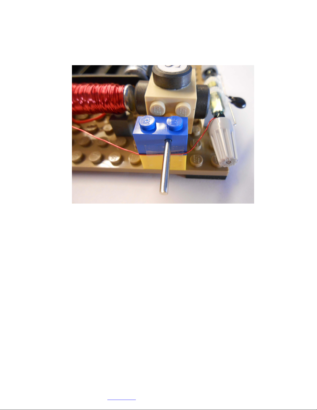
15.Attach the battery holder to the base plate.
16.Insert the batteries and briefly connect electromagnet wires to the battery holder wires. If
nothing happens switch the wires. With the correct connection electromagnet repels the
permanent magnets and the rotor stops in the position shown.

Assembly instructions for kit #13 8
This is not aLego® product even if it contains Lego® bricks and plates. All warranties provided by Simple Motors.
LEGO® is atrademark ofthe LEGO Group ofcompanies which does not sponsor, authorize or endorse this product.
All rights reserved. 2013 Simple Motors, LLC ♦www.simplemotor.com ♦
17.After you found the correct connection trim red (positive) wire from the battery holder and
corresponding electromagnet wire. Remove the insulation from the wire tips and twist them
together. You may tack this connection under the battery holder.
18.Fasten the reed switch to 1x2 brick with side holes using cable ties. Trim them with scissors.
19.Assemble the reed switch on the base plate. Trim the wires as necessary and remove at
least 1” (2.5 cm) of insulation.
Assembly instructions for kit #13 9
This is not aLego® product even if it contains Lego® bricks and plates. All warranties provided by Simple Motors.
LEGO® is atrademark ofthe LEGO Group ofcompanies which does not sponsor, authorize or endorse this product.
All rights reserved. 2013 Simple Motors, LLC ♦www.simplemotor.com ♦
20.Form ZNR contacts as shown.
21.Wind bare wire ends tightly around the reed switch / ZNR contacts.
22.Screw twist-on connectors. Do not over tighten as you may break the reed switch!
Assembly instructions for kit #13 10
This is not aLego® product even if it contains Lego® bricks and plates. All warranties provided by Simple Motors.
LEGO® is atrademark ofthe LEGO Group ofcompanies which does not sponsor, authorize or endorse this product.
All rights reserved. 2013 Simple Motors, LLC ♦www.simplemotor.com ♦
23.If the head of the electromagnet is lower than the rotor axle you may add small 1x1 brick
as shown to have a better alignment. It also provides additional support for the
electromagnet.
You may tape the electromagnet wire that is connected to the reed switch to the side of the
rotor stand (clear tape is shown). Make sure the tape is below the axle hole.
Spin the rotor by hand. Make sure it does not hit the electromagnet, reed switch or wires.
You should hear the click every time the magnet passes the reed switch.
Your motor is ready to check. It should work on 1, 2, 3, or 4 batteries. On one battery it
may require a slight push if your electromagnet is not aligned with the motor axle or the
permanent magnets are not perfectly centered on the rotor.
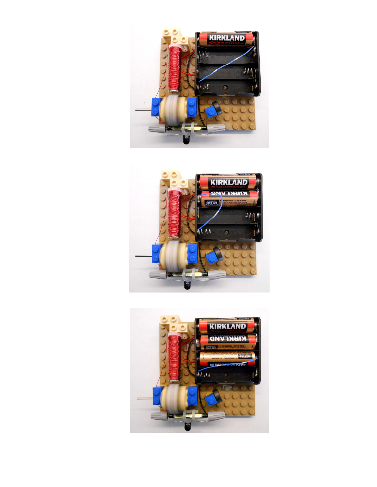
24.The included jumper wire allows you to experiment with 4 different voltage settings (1.5, 3,
4.5, and 6 V DC). You will need 4 AA size batteries.
Insert bare ends of the jumper wire between the spring and plastic case to make a good
contact and hold them in place.
The following pictures show typical usage of the jumper wire for 1, 2, or 3 batteries.
Please note that some battery holders may have different connections inside. If your battery
holder design is different you can still use the jumper wire in the same manner to get all 4
voltages, but you need to find appropriate connection points for each voltage setting.
Assembly instructions for kit #13 11
This is not aLego® product even if it contains Lego® bricks and plates. All warranties provided by Simple Motors.
LEGO® is atrademark ofthe LEGO Group ofcompanies which does not sponsor, authorize or endorse this product.
All rights reserved. 2013 Simple Motors, LLC ♦www.simplemotor.com ♦
1.5 Volts:
3 Volts:
4.5 Volts:
Assembly instructions for kit #13 12
This is not aLego® product even if it contains Lego® bricks and plates. All warranties provided by Simple Motors.
LEGO® is atrademark ofthe LEGO Group ofcompanies which does not sponsor, authorize or endorse this product.
All rights reserved. 2013 Simple Motors, LLC ♦www.simplemotor.com ♦
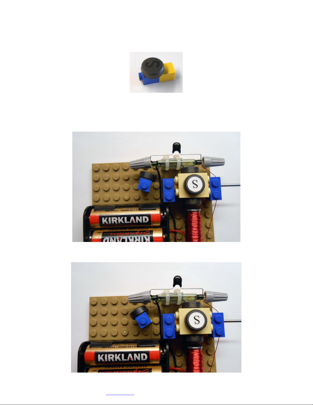
25.You may add speed control knob that allows changing the speed of the motor from
maximum to full stop. It may also increase the rotational speed 10-25%.
Assemble the speed control as shown and glue the magnet with the letter ‘S’ facing outside
(or dimple facing inside depending on magnet marking).
26.Speed control knob should be located as shown below and it provides the following speed
changes (positions are approximate, experiment with it yourself).
Full stop:
Slow speed:
Assembly instructions for kit #13 13
This is not aLego® product even if it contains Lego® bricks and plates. All warranties provided by Simple Motors.
LEGO® is atrademark ofthe LEGO Group ofcompanies which does not sponsor, authorize or endorse this product.
All rights reserved. 2013 Simple Motors, LLC ♦www.simplemotor.com ♦
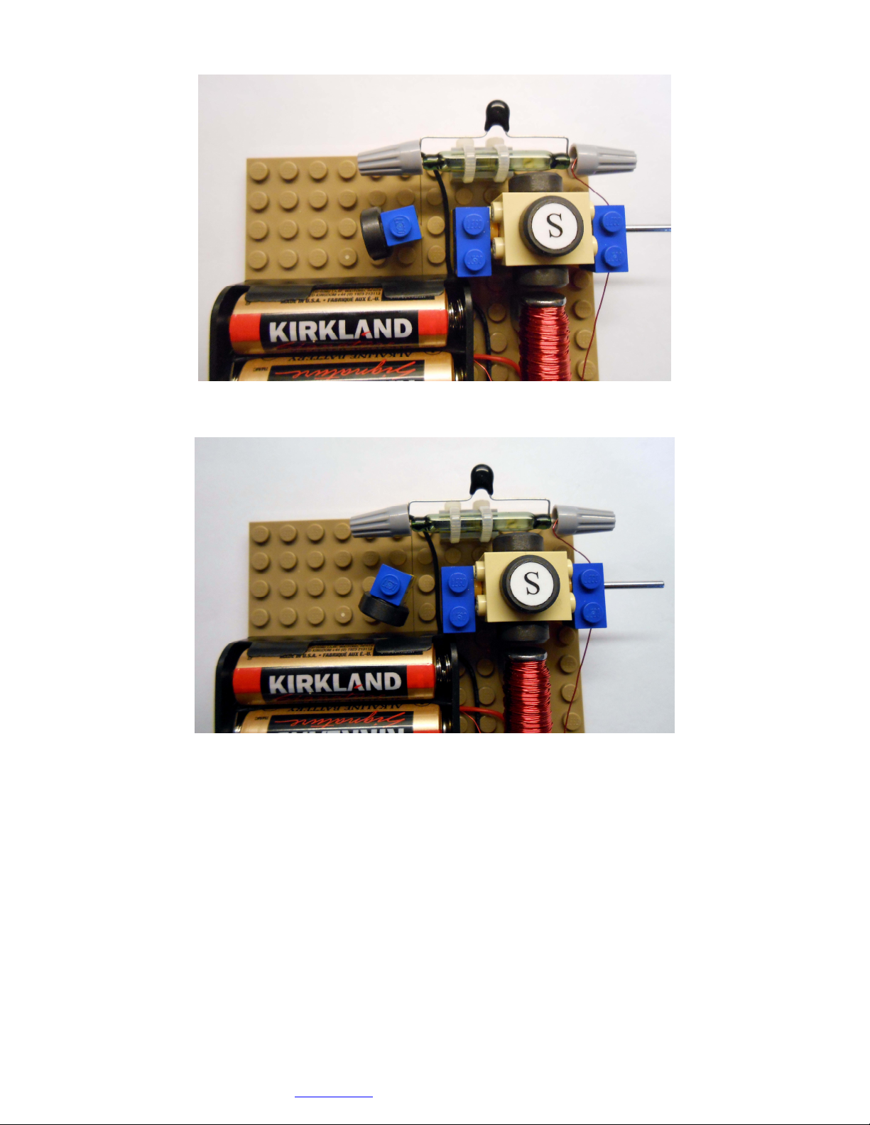
Regular speed (same as without speed control knob):
Maximum speed (may be 15-20% faster than regular):
Speed control magnet counteracts with the magnets on the rotor (that is why it is important
to have the same pole to face a reed switch). It changes the gap between the reed switch
contacts.
The phenomenon of increasing the speed is based on making the gap smaller allowing the
reed switch to work faster.
27.If you plan to add a generator from the generator kit to your motor you need to add 1x2
plate under the motor shaft.
Assembly instructions for kit #13 14
This is not aLego® product even if it contains Lego® bricks and plates. All warranties provided by Simple Motors.
LEGO® is atrademark ofthe LEGO Group ofcompanies which does not sponsor, authorize or endorse this product.
All rights reserved. 2013 Simple Motors, LLC ♦www.simplemotor.com ♦
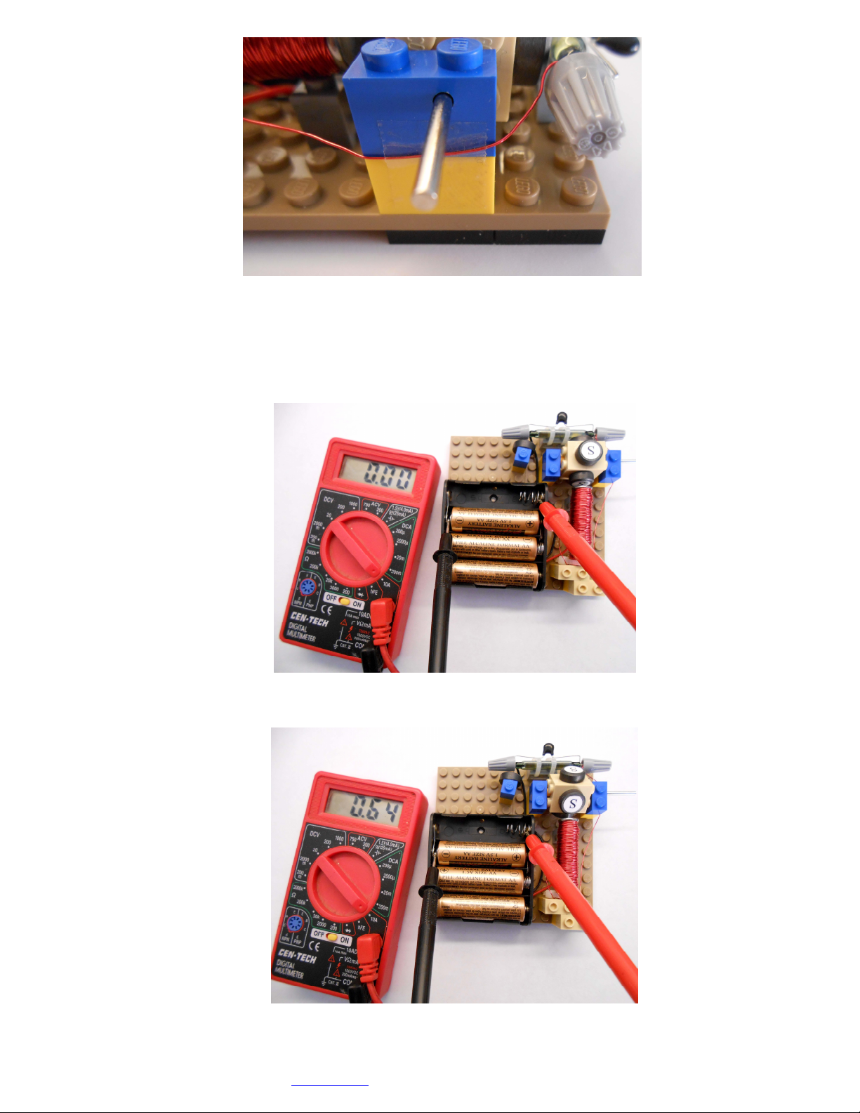
Using the speed control knob as a switch is possible but not advisable (removing one of the
batteries is a better option).
Here is the normal situation when the motor stops. There is no current going through the
circuit.
However if you accidentally move the rotor it may also stop in this position:

Assembly instructions for kit #13 15
This is not aLego® product even if it contains Lego® bricks and plates. All warranties provided by Simple Motors.
LEGO® is atrademark ofthe LEGO Group ofcompanies which does not sponsor, authorize or endorse this product.
All rights reserved. 2013 Simple Motors, LLC ♦www.simplemotor.com ♦
In this case the reed switch is activated by the speed control magnet but the rotor magnets
are out of reach. Motor looks like it is in a complete stop but in reality there is a big current
going through the circuit (it may exceed 1 A on 4 batteries). This current will quickly deplete
the batteries and can overheat and destroy the electromagnet.
Be aware of this possible scenario if you use the speed control as a switch.
You may glue bricks together and to the base plate if you do not plan to disassemble it. Do
not glue the speed control knob!
Visit our site at www.simplemotor.com for principles of this motor operation,
troubleshooting, speed measurement and other experiments.
Enjoy your motor! We hope you had fun building it.
* Colors of the parts may vary.
Other Simple Motors Engine manuals

Simple Motors
Simple Motors Kit 6 User manual

Simple Motors
Simple Motors Kit 8 User manual

Simple Motors
Simple Motors Kit 2 User manual

Simple Motors
Simple Motors Kit 5 User manual

Simple Motors
Simple Motors Kit 12 User manual

Simple Motors
Simple Motors Kit 17 User manual

Simple Motors
Simple Motors Kit 15 User manual

Simple Motors
Simple Motors Kit 11 User manual

Simple Motors
Simple Motors Kit 16 User manual

Simple Motors
Simple Motors Kit 9 User manual


