Austro Flamm SmartSpot User manual

User instructions
SmartSpot
www.austroflamm.com

User instructions
28/03/2023
Version: 1.0
LEGAL NOTICES
Owner and publisher
AUSTROFLAMM GMBH
Austroflamm-Platz 1
A- 4631 Krenglbach
Tel: +43 (0) 7249 / 46 443
www.austroflamm.com
Edited by: Olivera Stojanovic
Illustrations: Konstruktion
Text: Technical department (Austroflamm)
Copyright
All Rights reserved. The contents of these instructions may be reproduced or distributed only with the
consent of the publisher! Printing, spelling and typographical errors reserved.

SmartSpot Contents
3
Contents
1 General.................................................................................................................................................................. 4
2 Technical data ...................................................................................................................................................... 5
3 Putting the SmartSpot sensor into operation.................................................................................................. 6
4 Connecting the SmartSpot sensor with the XL display (from YC 2020) ..................................................... 7
5 Installing the SmartSpot receiver...................................................................................................................... 9
6 Connecting the SmartSpot sensor to the receiver.......................................................................................... 10
7 Additional functions of the SmartSpot sensor ................................................................................................ 11
8 LED colour codes and error causes................................................................................................................... 12

1 | General EN SmartSpot
4
1 General
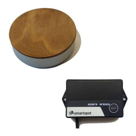
Thank you for deciding in favour of the Austroflamm SmartSpot room temperature sensor. This allows
you to record the current room temperature at the position of your choice in the room. It is connected
to the stove by Bluetooth wireless technology.
Depending on the stove model, the installation of a SmartSpot Receiver may be necessary for the
SmartSpot to work.

SmartSpot EN 2 | Technical data
5
2 Technical data
Dimensions 84 x 28 mm
Weight 100 g
Battery 2 x AAA batteries (inc.)
Battery service life > 1 year
Signal range (outside/inside) 40 m / 20 m
Environmental temperature -20 to +70 °C
Connection 2.4 GHz
Temperature recording range and accuracy -40 to +85 °C, +/- 1 °C
Installation position horizontal or vertical
Protection class IP22

3 | Putting the SmartSpot sensor into operation EN SmartSpot
6
3 Putting the SmartSpot sensor into operation
For the initial startup of the sensor, turn the SmartSpot with
the back pointing upwards.
Twist the bottom part of the body to the right. Now undo
the top and bottom parts from each other.
Removing the insulating strip from the battery contacts.

SmartSpot EN 4 | Connecting the SmartSpot sensor with the XL
display (from YC 2020)
7
4 Connecting the SmartSpot sensor with the XL display (from YC
2020)
Stove models which have an XL display from year of construction 2020 do not require a SmartSpot re-
ceiver. Here the SmartSpot sensor can be directly connected to the display.
1) In the settings, switch to “Bluetooth devices”. Start the
function “Add device”.
2) Press “Connect”. A new device will be looked for.
3) Now briefly press once the button marked “1” inside
the SmartSpot sensor.
4) After a few seconds the connection will be confirmed.

4 | Connecting the SmartSpot sensor with the XL
display (from YC 2020)
EN SmartSpot
8
5) The desired application of the room sensor can now
be selected.
6) Select the “Room temp” setting for the stove to con-
trol the temperature recorded by the SmartSpot.
7) The “SmartSpot” wireless room sensor is connected to
the stove.
8) Warning - no connection to the SmartSpot

SmartSpot EN 5 | Installing the SmartSpot receiver
9
5 Installing the SmartSpot receiver
NOTICE
Have the installation carried out by a professional.
When the SmartSpot receiver is being connected to the controls, the stove must be disconnected from
the mains!
The controls are situated behind one of the cladding panels of the stove. Which panel depends upon
the stove model. The corresponding side cladding must be removed beforehand.
The wired room sensor installed as standard on the “T01” connection of the control board must be ter-
minated. (Disconnect the QUICK RELEASE PLUG or remove 2 x black wires from the cable connector)
Then connect the SmartSpot receiver to the controls as follows.

6 | Connecting the SmartSpot sensor to the receiver EN SmartSpot
10
6 Connecting the SmartSpot sensor to the receiver
The SmartSpot receiver must be connected to the oven controls and supplied with power. (CHECK:
LED on the receiver is slowly flashing green.)
The SmartSpot sensor’s batteries must be correctly inserted.
Now briefly press the SmartSpot sensor's button marked
“1”. The LED will now flash green.
Then press the “Setup” button on the receiver. The LED be-
gins to quickly flash green.
Establishing the connection takes approximately 30 seconds. When the connection is successful, the
LED on the receiver will be continuously lit green and the sensor will flash briefly every 3 minutes.
The temperature display and control will now work as they would with the wired temperature sensor.

SmartSpot EN 7 | Additional functions of the SmartSpot sensor
11
7 Additional functions of the SmartSpot sensor
FLASHING SIGNAL - FUNCTION CONFIRMATION:
The SmartSpot Sensor briefly flashes as a “sign of life” every 3 minutes. The colour and function of this
processing confirmation can be changed. To do so, hold down the button marked “1”. Keep the key
pressed for as long as it takes for your desired colour to light up.
You can however also turn this function off.
Rapid flashing of the LED signals that this COLOUR SETTING FUNCTION has been disabled.

8 | LED colour codes and error causes EN SmartSpot
12
8 LED colour codes and error causes
SmartSpot sensor
LED Status Possible cause Solution
LED does not light up • Insulating strip for batteries
not removed
• Missing or dead battery
• Battery polarity wrong
• “Sign of life” function
• disabled
• Remove insulating strip
• Check batteries
• Insert batteries correctly
• Hold down the appropriate
button
• to enable the “Life” function
again
LED quickly flashing green • The sensor is looking for a
connection
• On the receiver or display,
also press the button for
“Connect”
LED flashes yellow • Battery low • Battery status <20%
LED flashes red • Battery dead • Battery status <10%
No or wrong temperature value • SmartSpot is not connected • Connect SmartSpot as per in-
structions
No connection • The SmartSpot is too far away • Reduce the distance to the
stove
Recorded temperature is too high • SmartSpot is incorrectly
placed
• Avoid direct sunlight, proxim-
ity to electrical devices and
other heat sources when us-
ing SMART SPOT
Connection is often broken • SmartSpot is too far away
from the receiver / display
• Reduce distance to receiver /
display
SmartSpot receiver
LED Status Possible cause Solution
slowly flashing green • No connection to sensor • Connect to sensor as per in-
structions
quickly flashing green • Receiver is looking for con-
nection
• Also press the connection
button on the sensor
Green is lit up • Connection to the sensor
maintained
• Function OK
Green is lit up
Red flashing
• Battery on the sensor is dead • Change battery on the sensor
Green is lit up
Red is lit up
• FACTORY reset • The receiver has been reset
to factory settings
No connection • The SmartSpot is too far away • Reduce the distance to the
stove

13
Notizen / notes / appunti / remarques

AUSTROFLAMM GMBH
Austroflamm-Platz 1
A- 4631 Krenglbach
Tel: +43 (0) 7249 / 46 443
www.austroflamm.com
940299
Other manuals for SmartSpot
1
Table of contents
Other Austro Flamm Temperature Controllers manuals
Popular Temperature Controllers manuals by other brands
BLUE JAY
BLUE JAY BJ-S-W2S2-K2 user manual

Hitachi
Hitachi YUTAKI S80 R410A Series Installation and operation manual

Fuji Electric
Fuji Electric PXR3 Series Operation manual

esera automation
esera automation 11130 user guide

HB-THERM
HB-THERM M8150-EN Assembly instructions

TCNet
TCNet Boiler Controller User and service manual

LK Systems
LK Systems ICS-RF8 Assembly instructions

Thermo Technologies
Thermo Technologies USDT 2004 Installation and user guide

Advantage
Advantage SENTRA SR Series instruction manual

TREND
TREND T/PC installation instructions

Veris
Veris TW2 Protocol Series installation guide

Advanjet
Advanjet Diaphragm-Jet 60-2257 instructions