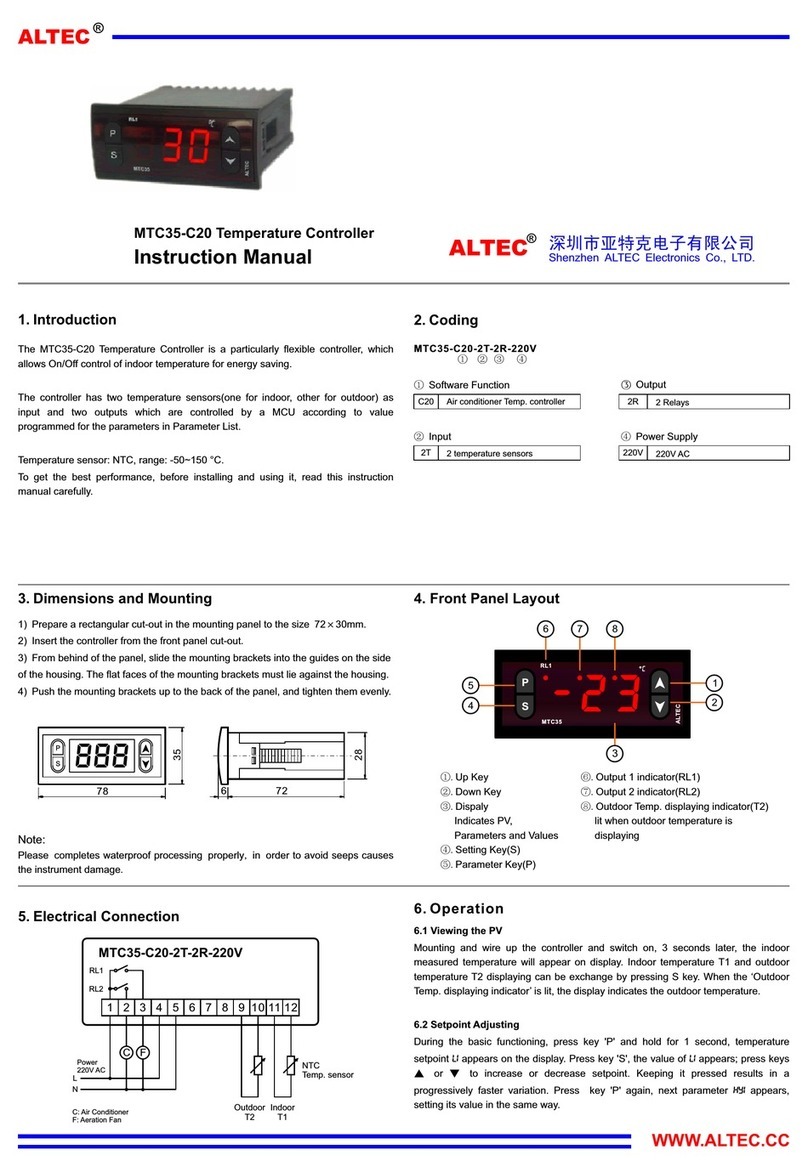
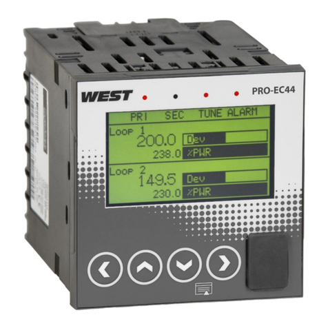
Advanjet Diaphragm-Jet 60-2257 User manual

Instructions
Temperature Controller
3A5912A
Diaphragm-Jet™Technology EN
Replacement temperature controller P/N 60-2257 for the Advanjet HV-2000C,
HV-2100C, and HM-2600C Jet Controller.
For professional use only.
Important Safety Instructions
Read all warnings and instructions in this manual and all related
manuals before using this equipment. Save these instructions.
PROVEN QUALITY. LEADING TECHNOLOGY.

Contents
Related Manuals............................................................................................................ 2
1. Repair Procedure................................................................................................ 3
2. HV-2000C............................................................................................................. 4
2.1 HV-2000C Jet Temperature Controller Connections ................................. 4
2.2 HV-2000C Jet Temperature Controller Settings ........................................ 5
3. HV-2100C............................................................................................................. 6
3.1 HV-2100C Jet Temperature Controller Connections ................................. 6
3.2 HV-2100C Jet Temperature Controller Settings ........................................ 7
4. HM-2600C ............................................................................................................ 8
4.1 HM-2600C Jet and Fluid Temperature Controller Connections ................. 8
4.2 HM-2600C Jet and Fluid Temperature Controller Settings ........................ 9
Graco Standard Warranty........................................................................................... 10
Related Manuals
Manuals are available at www.graco.com. Component manuals below are in English:
3A5856
HV-2000C Jet Controller Setup and Operation
3A6226
HV-2100C Jet Controller Setup and Operation
3A6166
HM-2600C Hotmelt Jet Controller Setup and Operation
Page 2 of 10 Advanjet Temperature Controller Repair 3A5912A

1. Repair Procedure
This document describes the procedure for replacing the temperature controller
(P/N 60-2257) for the Advanjet HV-2000C, HV-2100C, and HM-2600C Jet Controllers.
This procedure replaces the temperature controller and installs the Advanjet settings.
Use the power switch on the controller front panel to turn the main power OFF.1.
Disconnect the power cord on the rear of the controller.
Remove the controller top cover.2.
Disconnect the wires from the pins of the old controller(s). Remove and recycle3.
the old controller(s) per local regulations.
Use the appropriate pin connection chart and diagram in Section 2 (HV-2000C),4.
Section 3 (HV-2100C), or Section 4 (HM-2600C) to install the new temperature
controller.
Replace the controller top cover.5.
Reconnect the controller power cord and turn the main power ON.6.
Use the appropriate controller settings chart in Section 2, 3, or 4 to change the7.
temperature controller default manufacturer settings to the values required for the
Advanjet controller.
WARNING
ELECTRIC SHOCK HAZARD
Improper setup, usage, or grounding of the system can cause electric shock.
• Turn off power and disconnect power cord before removing the Advanjet controller cover.
• Be sure that all power is off when disconnecting and reconnecting wires.
• Replace Advanjet controller cover before reconnecting the power cord.
3A5912A Advanjet Temperature Controller Repair Page 3 of 10

2. HV-2000C
2.1 HV-2000C Jet Temperature Controller Connections
WARNING
ELECTRIC SHOCK HAZARD
Improper setup, usage, or grounding of the system can cause electric shock.
• Turn off power and disconnect power cord before removing the Advanjet controller cover.
• Be sure that all power is off when disconnecting and reconnecting wires.
• Replace Advanjet controller cover before reconnecting the power cord.
PIN
COLOR
1
BROWN
2
RED
3
ORANGE
4
YELLOW
5
GREEN
6
--
7
--
8
--
9
WHITE
10
BLACK
11
BLACK (A/C – L)
12
WHITE (A/C – N)
13
BLUE
14
VIOLET
15
GRAY
Page 4 of 10 Advanjet Temperature Controller Repair 3A5912A

2.2 HV-2000C Jet Temperature Controller Settings
After installing the new temperature controller, the manufacturer’s default settings must
be changed to the following settings. These are the values required to use the Advanjet
HV-2000C controller and the HV-2000 Jet nozzle plate for the majority of applications.
Use the keys to adjust values. Press once to save changes,
and then press again to return to the previous menu.
OPERATION
Description
Setting
Value
Press
Control Run/Stop setting
r-S
Upper-limit alarm 1
AL1H
3
Lower-limit alarm 1
AL1L
3
Upper-limit alarm 2
AL2H
3
Lower-limit alarm 2
AL2L
3
LOC
oFF
REGULATION
Description
Setting
Value
Press once, then press
PB (Proportional band)
P
4
Ti (Integral time)
i
20
Td (Derivative time)
d
5
Default value of Integral Volume
ioF
0
Heating Control Cycle Setting
HtPd
10
Process Temperature Offset
tPoF
0
INITIAL SETTINGS
Description
Setting
Value
Press and hold
Input temperature sensor type
inPt
Pt2
Temperature unit display selection
tPUn
C
Upper-limit of temperature range
tP-H
75
Lower-limit of temperature range
tP-L
-20
Control method
Ctrl
PiD
Heating/Cooling control Selection
S-HC
HEAt
Alarm 1 type
ALA1
1
Alarm 2 type
ALA2
1
Data Format
C-5L
ASCII
Communication write-in selection
Co5H
on
Controller Address
C-no
1
Baud Rate Setting
bP5
9600
Communication Data Length
LEn
8
Communication Parity Bit
Prty
nonE
Communication Stop Bit
Stop
1
3A5912A Advanjet Temperature Controller Repair Page 5 of 10

3. HV-2100C
3.1 HV-2100C Jet Temperature Controller Connections
WARNING
ELECTRIC SHOCK HAZARD
Improper setup, usage, or grounding of the system can cause electric shock.
• Turn off power and disconnect power cord before removing the Advanjet controller cover.
• Be sure that all power is off when disconnecting and reconnecting wires.
• Replace Advanjet controller cover before reconnecting the power cord.
PIN
COLOR
1
BROWN
2
RED
3
ORANGE
4
YELLOW
5
YELLOW JUMP TO PIN #4
6
--
7
--
8
--
9
WHITE
10
BLACK
11
BLACK (A/C – L)
12
WHITE (A/C – N)
13
BLUE
14
VIOLET
15
GRAY
Page 6 of 10 Advanjet Temperature Controller Repair 3A5912A

3.2 HV-2100C Jet Temperature Controller Settings
After installing the new temperature controller, the manufacturer’s default settings must
be changed to the following settings. These are the values required to use the Advanjet
HV-2100C controller and the HV-2100 Jet nozzle plate for the majority of applications.
Use the keys to adjust values. Press once to save changes,
and then press again to return to the previous menu.
OPERATION
Description
Setting
Value
Press
Control Run/Stop setting
r-S
Upper-limit alarm 1
AL1H
3
Lower-limit alarm 1
AL1L
3
Upper-limit alarm 2
AL2H
3
Lower-limit alarm 2
AL2L
3
LOC
off
REGULATION
Description
Setting
Jet
Press once,
then press
PB (Proportional band)
P
9
Ti (Integral time)
i
20
Td (Derivative time)
d
5
Default value of Integral Volume
ioF
0
Heating Control Cycle Setting
HtPd
10
Process Temperature Offset
tPoF
0
INITIAL SETTINGS
Description
Setting
Jet
Press and hold
Input temperature sensor type
inPt
Pt2
Temperature unit display selection
tPUn
C
Upper-limit of temperature range
tP-H
150
Lower-limit of temperature range
tP-L
-20
Control method
Ctrl
PiD
Heating/Cooling control Selection
S-HC
HEAt
Alarm 1 type
ALA1
1
Alarm 2 type
ALA2
1
Data Format
C-5L
ASCII
Communication write-in selection
Co5H
on
Controller Address
C-no
1
Baud Rate Setting
bP5
9600
Communication Data Length
LEn
8
Communication Parity Bit
Prty
nonE
Communication Stop Bit
Stop
1
3A5912A Advanjet Temperature Controller Repair Page 7 of 10

4. HM-2600C
4.1 HM-2600C Jet and Fluid Temperature Controller Connections
JET TEMPERATURE CONTROLLER
FLUID TEMPERATURE CONTROLLER
PIN
COLOR
PIN
1
BROWN
1
VIOLET (2)
2
BLACK
2
BLACK (2)
3
ORANGE
3
GRAY
4
YELLOW
4
WHITE
5
YELLOW
jump to JET pin #4
5
WHITE
jump to FLUID pin #4
6
--
6
--
7
--
7
--
8
--
8
--
9
WHITE
9
WHITEjump to JET pin #9
10
BLACK
10
BLACKjump to JET pin #10
11
BLACK (A/C - L)
11
BLACK (A/C - L) jump to JET pin #11
12
WHITE (A/C – N)
12
WHITE (A/C – N jump to JET pin #12
13
BLUE
13
BLUE jump to JET pin #13
14
VIOLET
14
VIOLET jump to JET pin #14
15
GRAY
15
GRAY
jump to JET pin #15
WARNING
ELECTRIC SHOCK HAZARD
Improper setup, usage, or grounding of the system can cause electric shock.
• Turn off power and disconnect power cord before removing the Advanjet controller cover.
• Be sure that all power is off when disconnecting and reconnecting wires.
• Replace Advanjet controller cover before reconnecting the power cord.
JET
FLUID
Page 8 of 10 Advanjet Temperature Controller Repair 3A5912A

4.2 HM-2600C Jet and Fluid Temperature Controller Settings
After installing the new temperature controller, the manufacturer’s default settings must
be changed to the following settings. These are the values required to use the Advanjet
HM-2600C controller and the HM-2600 Hotmelt Jet nozzle plate and fluid heater for the
majority of applications.
Use the keys to adjust values. Press once to save changes,
and then press again to return to the previous menu.
OPERATION
Description
Setting
Jet
Fluid
Press
Control Run/Stop setting
r-S
Upper-limit alarm 1
AL1H
3
3
Lower-limit alarm 1
AL1L
3
3
Upper-limit alarm 2
AL2H
3
3
Lower-limit alarm 2
AL2L
3
3
LOC
off
off
REGULATION
Description
Setting
Jet
Fluid
Press once,
then press
PB (Proportional band)
P
9
9.6
Ti (Integral time)
i
20
25
Td (Derivative time)
d
5
6
Default value of Integral Volume
ioF
0
66
Heating Control Cycle Setting
HtPd
10
10
Process Temperature Offset
tPoF
0
0
INITIAL SETTINGS
Description
Setting
Jet
Fluid
Press and hold
Input temperature sensor type
inPt
Pt2
Pt2
Temperature unit display selection
tPUn
C
C
Upper-limit of temperature range
tP-H
150
120
Lower-limit of temperature range
tP-L
-20
-20
Control method
Ctrl
PiD
PiD
Heating/Cooling control Selection
S-HC
HEAt
HEAt
Alarm 1 type
ALA1
1
1
Alarm 2 type
ALA2
1
1
Data Format
C-5L
ASCII
ASCII
Communication write-in selection
Co5H
on
on
Controller Address
C-no
1
2
Baud Rate Setting
bP5
9600
9600
Communication Data Length
LEn
8
8
Communication Parity Bit
Prty
nonE
nonE
Communication Stop Bit
Stop
1
1
3A5912A Advanjet Temperature Controller Repair Page 9 of 10

Graco Standard Warranty
Graco warrants all equipment referenced in this document which is manufactured by Graco and bearing its name to be free from
defects in material and workmanship on the date of sale to the original purchaser for use. With the exception of any special,
extended, or limited warranty published by Graco, Graco will, for a period of twelve months from the date of sale, repair or replace
any part of the equipment determined by Graco to be defective. This warranty applies only when the equipment is installed,
operated and maintained in accordance with Graco’s written recommendations.
This warranty does not cover, and Graco shall not be liable for general wear and tear, or any malfunction, damage or wear caused
by faulty installation, misapplication, abrasion, corrosion, inadequate or improper maintenance, negligence, accident, tampering, or
substitution of non-Graco component parts. Nor shall Graco be liable for malfunction, damage or wear caused by the incompatibility
of Graco equipment with structures, accessories, equipment or materials not supplied by Graco, or the improper design,
manufacture, installation, operation or maintenance of structures, accessories, equipment or materials not supplied by Graco.
This warranty is conditioned upon the prepaid return of the equipment claimed to be defective to an authorized Graco distributor for
verification of the claimed defect. If the claimed defect is verified, Graco will repair or replace free of charge any defective parts. The
equipment will be returned to the original purchaser transportation prepaid. If inspection of the equipment does not disclose any
defect in material or workmanship, repairs will be made at a reasonable charge, which charges may include the costs of parts, labor,
and transportation.
THIS WARRANTY IS EXCLUSIVE, AND IS IN LIEU OF ANY OTHER WARRANTIES, EXPRESS OR IMPLIED, INCLUDING BUT
NOT LIMITED TO WARRANTY OF MERCHANTABILITY OR WARRANTY OF FITNESS FOR A PARTICULAR PURPOSE.
Graco’s sole obligation and buyer’s sole remedy for any breach of warranty shall be as set forth above. The buyer agrees that no
other remedy (including, but not limited to, incidental or consequential damages for lost profits, lost sales, injury to person or
property, or any other incidental or consequential loss) shall be available. Any action for breach of warranty must be brought within
two (2) years of the date of sale.
GRACO MAKES NO WARRANTY, AND DISCLAIMS ALL IMPLIED WARRANTIES OF MERCHANTABILITY AND FITNESS FOR
A PARTICULAR PURPOSE, IN CONNECTION WITH ACCESSORIES, EQUIPMENT, MATERIALS OR COMPONENTS SOLD
BUT NOT MANUFACTURED BY GRACO. These items sold, but not manufactured by Graco (such as electric motors, switches,
hose, etc.), are subject to the warranty, if any, of their manufacturer. Graco will provide purchaser with reasonable assistance in
making any claim for breach of these warranties.
In no event will Graco be liable for indirect, incidental, special or consequential damages resulting from Graco supplying equipment
hereunder, or the furnishing, performance, or use of any products or other goods sold hereto, whether due to a breach of contract,
breach of warranty, the negligence of Graco, or otherwise.
FOR GRACO CANADA CUSTOMERS
The Parties acknowledge that they have required that the present document, as well as all documents, notices and legal
proceedings entered into, given or instituted pursuant hereto or relating directly or indirectly hereto, be drawn up in English. Les
parties reconnaissent avoir convenu que la rédaction du présente document sera en Anglais, ainsi que tous documents, avis et
procédures judiciaires exécutés, donnés ou intentés, à la suite de ou en rapport, directement ou indirectement, avec les procédures
concernées.
Graco Information
For the latest information about Advanjet products, visit www.advanjet.com.
For patent information, see www.graco.com/patents.
For customer service and technical assistance, e-mail info@advanjet.com
TO PLACE AN ORDER, contact orders@advanjet.com
If calling from the US: 800-333-4877
If calling from outside the US: +1-760-294-3392
All written and visual data contained in this document reflects the latest product information available at the time of publication.
Graco reserves the right to make changes at any time without notice.
Original instructions. This manual contains English. MM 3A5912A
Graco Headquarters: Minneapolis
International Offices: Belgium, China, Japan, Korea
GRACO INC. AND SUBSIDIARIES • P.O. BOX 1441 • MINNEAPOLIS MN 55440-1441 • USA
Copyright 2019, Graco Inc. All Graco manufacturing locations are registered to ISO 9001.
www.graco.com
Revision A, March 2019
Table of contents
