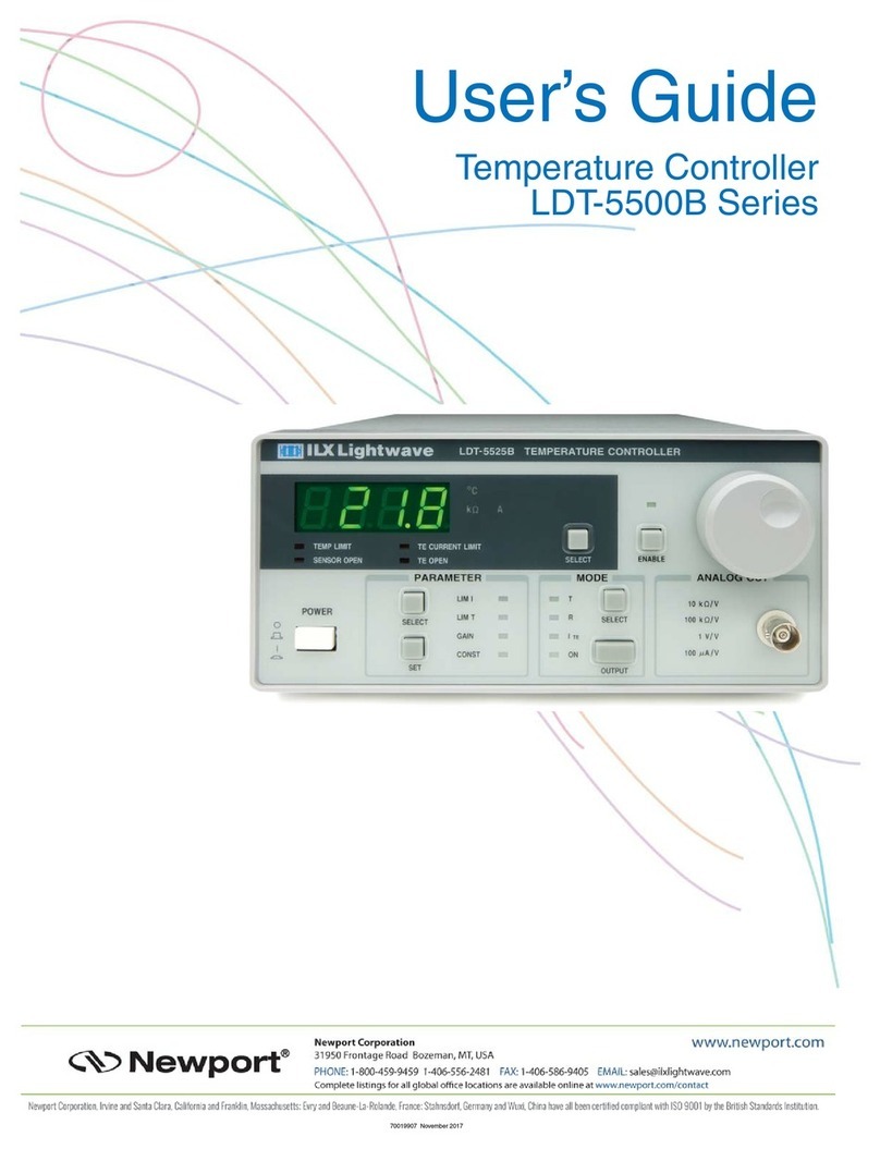
Newport ILX Lightwave LDT-5910C User manual

User’s Guide
Thermoelectric Temperature Controllers
LDT-5910C
LDT-5940C
70045102 March 2019


March 2019 i LDT-5910C and LDT-5940C
Table of Contents
Safety Information and the Manual.............................................................................v
General Safety Considerations...................................................................................v
Safety Symbols.......................................................................................................... vi
Safety Marking Symbols........................................................................................... vii
Warranty................................................................................................................... vii
Limitations ................................................................................................................ vii
Returning an Instrument .......................................................................................... viii
Claims for Shipping Damage..........................................................................................................viii
Comments, Suggestions, and Problems ................................................................... ix
Chapter 1: Introduction and Specifications ................................................. 1
Safety Considerations ................................................................................................1
Initial Inspection..........................................................................................................1
Shipping Kit ................................................................................................................1
Product Overview .......................................................................................................2
Options and Accessories............................................................................................5
Specifications .............................................................................................................6
Chapter 2: General Operation..................................................................... 9
Grounding Requirements ...........................................................................................9
AC Line Power Requirements ....................................................................................9
The Power Up Sequence ...........................................................................................9
Firmware Upgradeability...........................................................................................10
GPIB Communication ...............................................................................................10
USB Communication ................................................................................................10
Tilt Foot Adjustment..................................................................................................10
Rack Mounting..........................................................................................................10
Connections..............................................................................................................11
Front Panel Operation ..............................................................................................13
Power On / Off................................................................................................................................13
Adjust Knob and Enable Button .....................................................................................................13

March 2019 ii LDT-5910C and LDT-5940C
Setup ..............................................................................................................................................13
PID Control .....................................................................................................................................15
Mode...............................................................................................................................................16
Display............................................................................................................................................16
Error Indicators ...............................................................................................................................17
General Operating Procedures.................................................................................17
Warm-Up and Environmental Considerations................................................................................17
General Guidelines for Sensor Selection and Safety Limits ..........................................................17
Sensor Options...............................................................................................................................17
Safety Limits ...................................................................................................................................22
Constant Temperature Mode Operation ...................................................................22
Constant Sensor Mode Operation ............................................................................22
Constant Current Mode Operation............................................................................24
Resistive Heater Mode Operation.............................................................................24
Chapter 3: Remote Operation................................................................... 25
GPIB Address...........................................................................................................25
Basic GPIB Concepts ...............................................................................................25
Data and Interface Messages ........................................................................................................25
Talkers, Listeners, and Controllers.................................................................................................26
GPIB Cable Connections ...............................................................................................................26
The GPIB Connector ......................................................................................................................27
Reading the GPIB Address ............................................................................................................28
Changing the GPIB Address ..........................................................................................................28
Basic USB concepts .................................................................................................28
Changing Between Local and Remote Operation.....................................................29
GPIB vs. USB Communication .................................................................................29
Command Syntax .....................................................................................................29
Letters.............................................................................................................................................29
White Space ...................................................................................................................................30
Terminators ....................................................................................................................................30
Command Separators ....................................................................................................................30
Parameters .....................................................................................................................................31
Command Tree Structure .........................................................................................32
Syntax Summary ......................................................................................................33
IEEE 488.2 Common Commands.............................................................................34
Status Reporting.......................................................................................................35
Event and Condition Registers.......................................................................................................35

March 2019 iii LDT-5910C and LDT-5940C
Operation Complete Definition..................................................................................36
Output Off Register...................................................................................................38
Command Timing .....................................................................................................39
Sequential / Overlapped Commands........................................................................39
Query Response Timing...........................................................................................39
Chapter 4: Command Reference ............................................................... 41
Remote Command Reference Summary..................................................................41
LDT-5910B Compatibility for LDT-5910C .................................................................44
Command Reference ...............................................................................................45
Chapter 5: Calibration and Troubleshooting ............................................. 65
Troubleshooting Guide .............................................................................................66
Error Messages ........................................................................................................69
Error Code Tables ..........................................................................................................................69
Calibration Overview ................................................................................................71
Recommended Equipment.............................................................................................................71
Environmental Conditions ..............................................................................................................71
Warm-up.........................................................................................................................................71
Calibration Adjustments .................................................................................................................71
Thermistor Calibration ....................................................................................................................72
Linearized Thermistor Mode Calibration ........................................................................................72
IC-I (AD590 or equivalent) Sensor Calibration...............................................................................73
IC-V (LM335 or Equivalent) Sensor Calibration .............................................................................73
RTD Sensor Calibration .................................................................................................................74
ITE Current Calibration...................................................................................................................74
TEC Voltage Measurement Calibration..........................................................................................76
Appendix A: AD590 and LM335 Sensor Calibration ................................. 77
AD590 Sensor ..........................................................................................................77
LM335 Sensor ..........................................................................................................78
One Point Calibration Method...................................................................................79
Two Point Calibration Method...................................................................................79
Appendix B: Auto-Tune Method................................................................ 81

March 2019 iv LDT-5910C and LDT-5940C

March 2019 v LDT-5910C and LDT-5940C
Safety and Warranty Information
Details about cautionary symbols
Safety markings used on the instrument
Information about the warranty
Customer service contact information
Safety Information and the Manual
Throughout this manual, you will see the words Caution and Warning indicating potentially
dangerous or hazardous situations which, if not avoided, could result in death, serious or minor injury,
or damage to the product. Specifically:
Caution indicates a potentially hazardous situation which can result in minor or moderate injury or
damage to the product or equipment.
Warning indicates a potentially dangerous situation which can result in serious injury or death.
Visible and/or invisible laser radiation. Avoid direct exposure to the beam.
General Safety Considerations
If any of the following conditions exist, or are even suspected, do not use the instrument until safe
operation can be verified by trained service personnel:
Visible damage
Severe transport stress
Prolonged storage under adverse conditions
Failure to perform intended measurements or functions
If necessary, return the instrument to ILX Lightwave, or authorized local ILX Lightwave distributor, for
service or repair to ensure that safety features are maintained.
All instruments returned to ILX Lightwave are required to have a Return Authorization Number
assigned by an official representative of ILX Lightwave Corporation. See Returning an Instrument for
more information.

March 2019 vi LDT-5910C and LDT-5940C
Safety Symbols
This section describes the safety symbols and classifications.
Technical specifications including electrical ratings and weight are included within the manual. See
the Table of Contents to locate the specifications and other product information. The following
classifications are standard across all ILX Lightwave products:
Indoor use only
Ordinary Protection: This product is NOT protected against the harmful ingress of
moisture.
IEC Class I Equipment (grounded type)
Mains supply voltage fluctuations are not to exceed ±10% of the nominal supply voltage.
Pollution Degree II
Installation (overvoltage) Category II for transient over-voltages
Maximum Relative Humidity: <85% RH, non-condensing
Operating temperature range of 10 °C to 40 °C
Storage and transportation temperature of –40 °C to 70 °C
Maximum altitude: 3000 m (9843 ft.)
This equipment is suitable for continuous operation.

March 2019 vii LDT-5910C and LDT-5940C
Safety Marking Symbols
This section provides a description of the safety marking symbols that appear on the instrument.
These symbols provide information about potentially dangerous situations which can result in death,
injury, or damage to the instrument and other components.
Caution, refer
to manual
Earth ground
Terminal Alternating current
Visible and/or
invisible laser
radiation
Caution, risk of
electric shock
Protective
Conductor
Terminal
Caution,
hot surface
Frame or chassis
terminal
Warranty
ILX Lightwave Corporation warrants this instrument to be free from defects in material and
workmanship for a period of one year from date of shipment. During the warranty period, ILX will
repair or replace the unit, at our option, without charge.
Limitations
This warranty does not apply to fuses, lamps, defects caused by abuse, modifications, or to use of
the product for which it was not intended.
This warranty is in lieu of all other warranties, expressed or implied, including any implied warranty of
merchantability or fitness for any particular purpose. ILX Lightwave Corporation shall not be liable for
any incidental, special, or consequential damages.
If a problem occurs, please contact ILX Lightwave Corporation with the instrument's serial number,
and thoroughly describe the nature of the problem.

March 2019 viii LDT-5910C and LDT-5940C
Returning an Instrument
If an instrument is to be shipped to ILX Lightwave for repair or service, be sure to:
Obtain a Return Authorization number (RA) from ILX Customer Service.
Attach a tag to the instrument identifying the owner and indicating the required service or
repair. Include the instrument serial number from the rear panel of the instrument.
Attach the anti-static protective caps that were shipped with the instrument.
Place the instrument in the original packing container with at least 3 inches (7.5 cm) of
compressible packaging material. Shipping damage is not covered by this warranty.
Secure the packing box with fiber reinforced strapping tape or metal bands.
Send the instrument, transportation pre-paid, to ILX Lightwave. Clearly write the return
authorization number on the outside of the box and on the shipping paperwork. ILX
Lightwave recommends you insure the shipment.
If the original shipping container is not available, place your instrument in a container with at
least 3 inches (7.5 cm) of compressible packaging material on all sides.
Repairs are made and the instrument returned transportation pre-paid. Repairs are warranted for the
remainder of the original warranty or for 90 days, whichever is greater.
Claims for Shipping Damage
When you receive the instrument, inspect it immediately for any damage or shortages on the packing
list. If the instrument is damaged, file a claim with the carrier. The factory will supply you with a
quotation for estimated costs of repair. You must negotiate and settle with the carrier for the amount
of damage.

March 2019 ix LDT-5910C and LDT-5940C
Comments, Suggestions, and Problems
To ensure that you get the most out of your ILX Lightwave product, we ask that you direct any
product operation or service related questions or comments to ILX Lightwave Customer Support. You
may contact us in whatever way is most convenient:
Phone (800) 459-9459 or (406) 586-1244
Fax (406) 586-9405
On the web at: ilx.custhelp.com
Or mail to:
ILX Lightwave Corporation
31950 East Frontage Road
Bozeman, Montana, U.S.A 59715-8642
www.ilxlightwave.com
When you contact us, please have the following information:
Model Number
Serial Number
End-user Name
Company
Phone
Fax
Description of what is connected to the ILX Lightwave instrument
Description of the problem
If ILX Lightwave determines that a return to the factory is necessary, you are issued a Return
Authorization (RA) number. Please mark this number on the outside of the shipping box.
You or your shipping service are responsible for any shipping damage when returning the instrument
to ILX Lightwave; ILX recommends you insure the shipment. If the original shipping container is not
available, place your instrument in a container with at least 3 inches (7.5 cm) of compressible
packaging material on all sides.
We look forward to serving you even better in the future!

March 2019 x LDT-5910C and LDT-5940C

March 2019 1 LDT-5910C and LDT-5940C
Chapter 1:
Introduction and Specifications
This chapter is an introduction to the LDT-5910C and LDT-5940C Thermoelectric Temperature
Controllers.
Safety Considerations and unpacking information
Product Overview
Options and accessories
Specifications
Safety Considerations
If any of the following symptoms exist, or are even suspected, remove the LDT-5910C or
LDT-5940C from service. Do not use the LDT-5910C or LDT-5940C until trained service
personnel can verify safe operation.
Visible damage
Severe transport stress
Prolonged storage under adverse conditions
Failure to perform intended measurements or functions
If necessary, return the LDT-5910C or LDT-5940C to ILX Lightwave for service and repair
to ensure that safety features are maintained.
Initial Inspection
When you receive your LDT-5910C or LDT-5940C Thermoelectric Temperature Controller, verity that
the following items were shipped with the instrument
LDT-5900C Series Thermoelectric Temperature Controller Manual
Power Cord
Shipping Kit
Shipping Kit
The shipping kit for the LDT-5910C and LDT-5940C Thermoelectric Temperature Controller includes
a USB A/B cable and a CD containing the ILX Lightwave USB Driver.

March 2019 2 LDT-5910C and LDT-5940C
Product Overview
The LDT-5910C and LDT-5940C are high performance thermoelectric temperature controllers
that offers a flexible, extended temperature control range from -100 °C to +200 °C with a choice
of temperature sensors. The LDT-5910C features a linear, bipolar output providing 32 Watts of
power to drive most thermal loads. This output stage offers the low current noise necessary to
achieve the temperature stability required to meet demanding low noise and frequency-
stabilized laser applications. The LDT-5940C features a switching output providing 60 Watts of
temperature control power for applications requiring increased cooling or heating capacity. The
instruments support thermistor, platinum RTD, and IC temperature sensors. In addition, a
unique linearized thermistor mode allows for the use of a standard 10 kthermistor over an
extended temperature range from -15 °C to 65 °C. A digital PID control loop delivers fast
settling time while maintaining high stability. For quick setup the LDT-5910C and LDT-5940C
incorporate pre-programmed PID values for common applications. In addition, a fast auto-tune
algorithm is available to automatically adjust the PID constants to support a wide range of
thermal loads. The GPIB and USB interfaces ensure trouble-free remote programming and
readout.
Features of the LDT-5910C and LDT-5940C include:
Precision setpoint resolution of ±0.01 °C with long term temperature stability of ±0.002 °C
(LDT-5910C) and ±0.003 °C (LDT-5940C)
Unique, linearized thermistor mode allows a standard 10 kthermistor to be used over the
range from -15 °C to 65 °C
Pseudo 4-Wire Sensor and TEC Measurement (LDT-5940C only)
Fully programmable PID control loop with twelve preset PID values
Auto-tune algorithm automatically adjusts PID constants for a wide range of loads
External analog temperature control input
Independent heating and cooling current limits
TE voltage measurement
Heat only control mode
Remote commands in LDT-5910C and LDT-5940C are compatible with LDT-5910B remote
commands
GPIB/IEEE 488 and USB Interfaces
Normally open and normally closed output interlock
Variable speed external fan control
If cleaning is required, use a clean dry cloth. Do not use solvents.

March 2019 3 LDT-5910C and LDT-5940C
Figure 1.1 – LDT-5910C and LDT-5940C Front Panel
Figure 1.2 – LDT-5910C Rear Panel

March 2019 4 LDT-5910C and LDT-5940C
Figure 1.4 – LDT-5940C Rear Panel

March 2019 5 LDT-5910C and LDT-5940C
Options and Accessories
Options and accessories available for LDT-5910C and LDT-5940C Thermoelectric Temperature
Controllers include the following:
DESCRIPTION MODEL / PART NUMBER
Single Rack Mount Kit RM-144
Dual Rack Mount Kit RM-145
Temperature Controller Interconnect Cable (terminated with 9-pin DSUB) CC-505S [5910C only]
Temperature Controller Interconnect Cable (unterminated) CC-501S [5910C only]
10 Amp TE Interconnect Cable (unterminated without fan connections) CC-591H [5940C only]
10 Amp TE Interconnect Cable (unterminated with fan connections) CC-594H [5940C only]
5 Amp TE/LDM Interconnect Cable (terminated with 9-pin DSUB) CC-595S [5940C only]
10 Amp TE Interconnect Cable (terminated with 7W2 DSUB) CC-596H [5940C only]
Calibrated 10 kThermistor TS-510
Uncalibrated 10 kThermistor TS-520
Uncalibrated 5 kThermistor TS-521
Uncalibrated 20 kThermistor TS-523
Uncalibrated 100 kThermistor TS-525
Uncalibrated AD590 IC Temperature Sensor TS-530
Uncalibrated LM335 IC Temperature Sensor TS-540
Unipolar Control Adapter UCA-350
TO-Can Laser Diode Mount LDM-4405
TO-Can Laser Diode Mount LDM-4407
C-Mount Laser Diode Mount LDM-4409
TO-Can Laser Diode Mount (with optional collimating lens) LDM-4412
TELECOM Laser Diode Mount LDM-4980
Production TO-Can Laser Diode Mount LDM-4990

March 2019 6 LDT-5910C and LDT-5940C
Specifications

March 2019 7 LDT-5910C and LDT-5940C

March 2019 8 LDT-5910C and LDT-5940C
This manual suits for next models
1
Table of contents
Other Newport Temperature Controllers manuals
