Autarco Apex R6 User manual

Installation Manual
Apex R6 Pitched Roof Mounting System
© Autarco Group B.V. IM-M1.R6-EN-V1.0
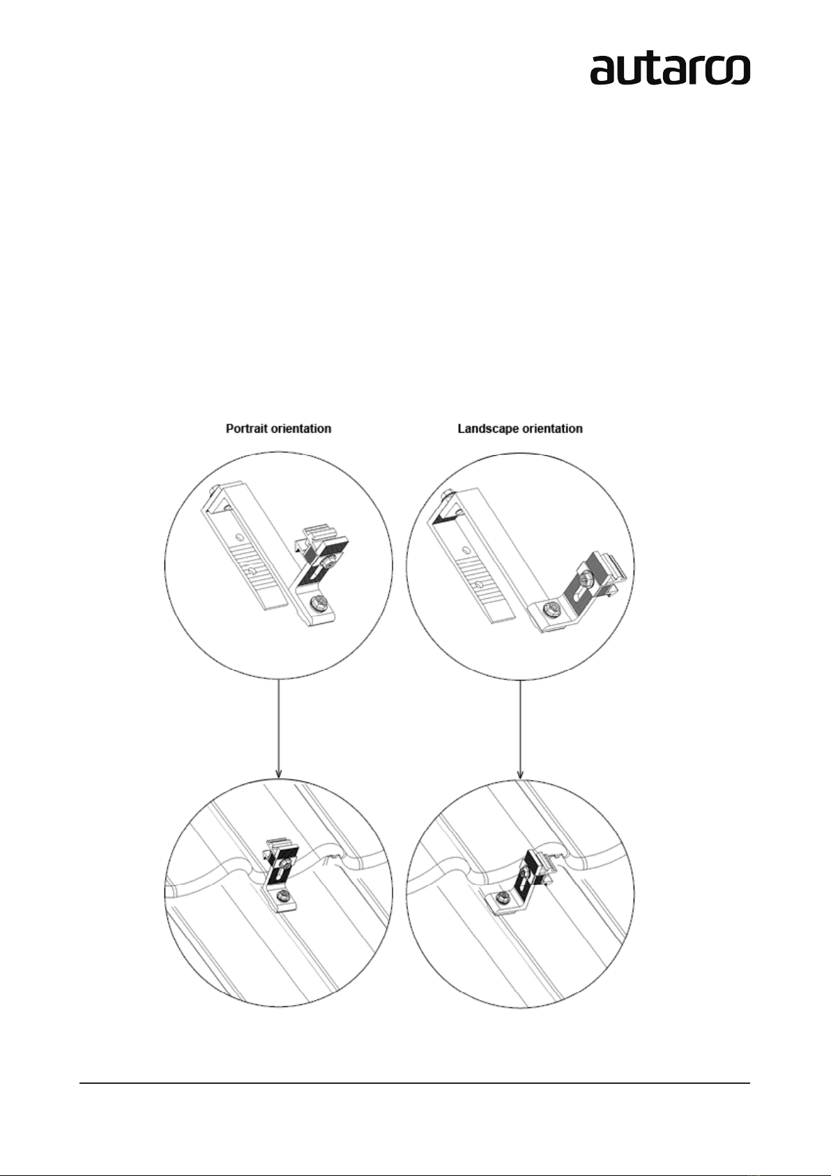
Portrait & Landscape Orientation

2R6 mounting system (Portrait and landscape)

installation manual
3
R6 mounting system (Portrait and landscape)
Contact Informaon
Autarco Group B.V.
Torenallee 20
5617 BC Eindhoven
The Netherlands
www.autarco.com
info@autarco.com
Other Informaon
This manual is an integral part of the unit. Please read the manual carefully before installaon, operaon or
maintenance. Keep this manual for future reference.
Product informaon is subject to change without noce. All trademarks are recognized as the property of their
respecve owners.
© Autarco Group B.V.
All rights reserved.

4R6 mounting system (Portrait and landscape)
Contents
1. Introducon 5
1.1 Safety Symbols 5
1.2 Target Audience 5
1.3 Mounng Hook Models Covered 5
2. Preparing for Installaon 6
2.1 Safety Instrucons 6
2.2 Package Contents 7
2.3 Tools & Materials Required 8
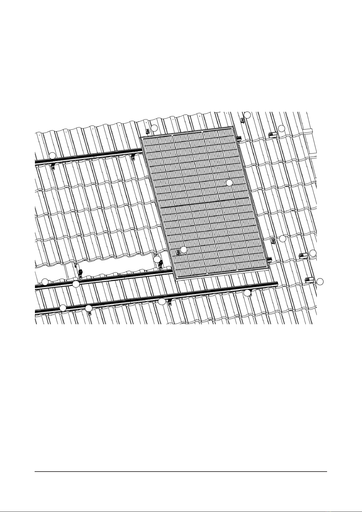
2.4 Solar Panel Posion Guideline 9
2.5 Hooks and Rails Posion Guideline 10
3. Installaon 11
3.1 Marking the posion of mounng hooks 12
3.2 Mounng hooks onto the roof 13
3.3 Aaching rails onto the hooks 15
3.4 Clamping modules into the rails 16
3.4.1 How to assemble clamps onto the rails 16
3.4.2 Anchoring the rails (portrait & landscape): 16
3.4.3 Installing rst module onto the rails with end clamps 17
3.4.4 Installing modules onto the rails with middle clamps 18
3.4.5 Securing nal module with end clamps 19
3.5 Installaon complete 20
4. Disposal 20
installation manual
5
R6 mounting system (Portrait and landscape)
1. Introducon
The main purpose of this installaon manual is to provide instrucons and detailed procedures for installing and
maintaining Autarco pitched roof mounng system based on R6 type rails on buildings up to 20m in height.
1.1 Safety Symbols
DANGER! A danger symbol indicates a hazardous situaon, which if not avoided, will result in death
or serious injury.
WARNING! Indicates a hazardous situaon which, if not avoided, can result in serious injury.
ATTENTION! Aenon statements are used to indicate where a part of the process or equipment
has a special requirement. Aenon statements should be followed at all mes.
1.2 Target Audience
This manual is intended for qualied personnel who installs an Autarco solar PV soluon with R6 pitched roof
mounng systems. Before any further acon, the installer must rst read all safety regulaons and be aware of the
potenal danger to operate high-voltage devices such as PV modules.
ATTENTION! Qualied personnel means a person with valid license from the local authority for:
• Installing electrical equipment and PV power systems (up to 1000 V)
• Applying all applicable installaon codes and using personal protecve equipment (PPE)
• Analyzing and reducing the hazards involved in performing electrical work
1.3 Mounng Hook Models Covered
The R6 rail is installed on a pitched roof using one of the following Autarco pitched roof mounng hooks:
• M2.AR6THX1 - Apex R6 adjustable roof hook for portrait and landscape install on le roofs
• M2.AR6WC.1 - Apex R6 waveclip for lanscape install on corrugated roofs
• M2.AR6HB.1 - Apex R6 hangerbolt for landscape install on corrugated roofs
Further informaon on the types of roof mounng hooks are available online at www.autarco.com/downloads/
6R6 mounting system (Portrait and landscape)
2. Preparing for Installaon
2.1 Safety Instrucons
DANGER! Do not install during severe or sub-zero weather condions.
WARNING! Never step or sit on the glass surface of a solar module.
The glass may break, resulng in shock or bodily injury. The module may also stop generang power.
WARNING! Always use the supplied parts to aach the solar modules and mounts.
Use of other parts is dangerous and may cause the solar modules or mounts to loosen or fall.
DANGER! Do not install this system on a roof with pitch > 60 degrees.
WARNING! The installaon, maintenance, recycling and disposal of the mounng components
must be performed by qualied personnel in compliance with naonal and local standards and
regulaons.
WARNING! Always install modules onto a minimum of two rails which are parallel to the shorter side
of the module.
Otherwise, loosening of the modules may occur due to expansion or contracon of the rails under
varying heat.
Any unauthorized acons including modicaon of product funconality of any form will aect the validaon of
warranty service; Autarco may deny the obligaon of warranty service accordingly.

installation manual
7
R6 mounting system (Portrait and landscape)
2.2 Package Contents
Solar Modules R6 Rail
SOLIDWORKS Student Edition.
For Academic Use Only.
Splice Connector End Cap End Clamp Middle Clamp
In this manual, we use the M2.AR6THX1.1 Mounng Hook 7a which can also be converted into the ‘screwed’ 7b
variaon.
THX1 Mounng Hook M2.AR6WC.1
Please note the component numberings as they will be referenced in the installaon secon.
SOLIDWORKS Student Edition.
For Academic Use Only.
SOLIDWORKS Student Edition.
For Academic Use Only.
M8×40
screw
1
7a
2
M8×40
screw
7b
3 4 5 6
M8×16
x4
M1.AR6RJ.1 M1.AR6CAP.1 M1.AR6EC.1 M1.AR6MC.1
MHI / MHJ / MHH M1.AR6L3300.1 / 3580 / 4350 / 4730
M2.AR6THX1.1 M2.AR6THX1.1 M2.AR6HB.1
7C M2.AR6HB.1

8R6 mounting system (Portrait and landscape)
2.3 Tools & Materials Required
A Wood Mounng Screw (maximum major diameter, 8.5mm)
e.g. Self-Tapping Screw ST6,3x19
Tape Measure
Marker or Chalk
Ratchet Electric Screw Driver
OR
Saw
1
2
3
4
5
6
or
S10
S10
Scaold or stable safe
ladder
Tape measure Brush Ratchet with hexagon Battery-operated drill
Felt-tip pen/chalk Mounting wedge/keg
1
2
3
4
5
6
or
S10 S10
Scaold or stable safe
ladder
Tape measure Brush Ratchet with hexagon Battery-operated drill
Felt-tip pen/chalk Mounting wedge/keg
SOLIDWORKS Student Edition.
For Academic Use Only.
B
C
E
D2
D1
installation manual
9
R6 mounting system (Portrait and landscape)
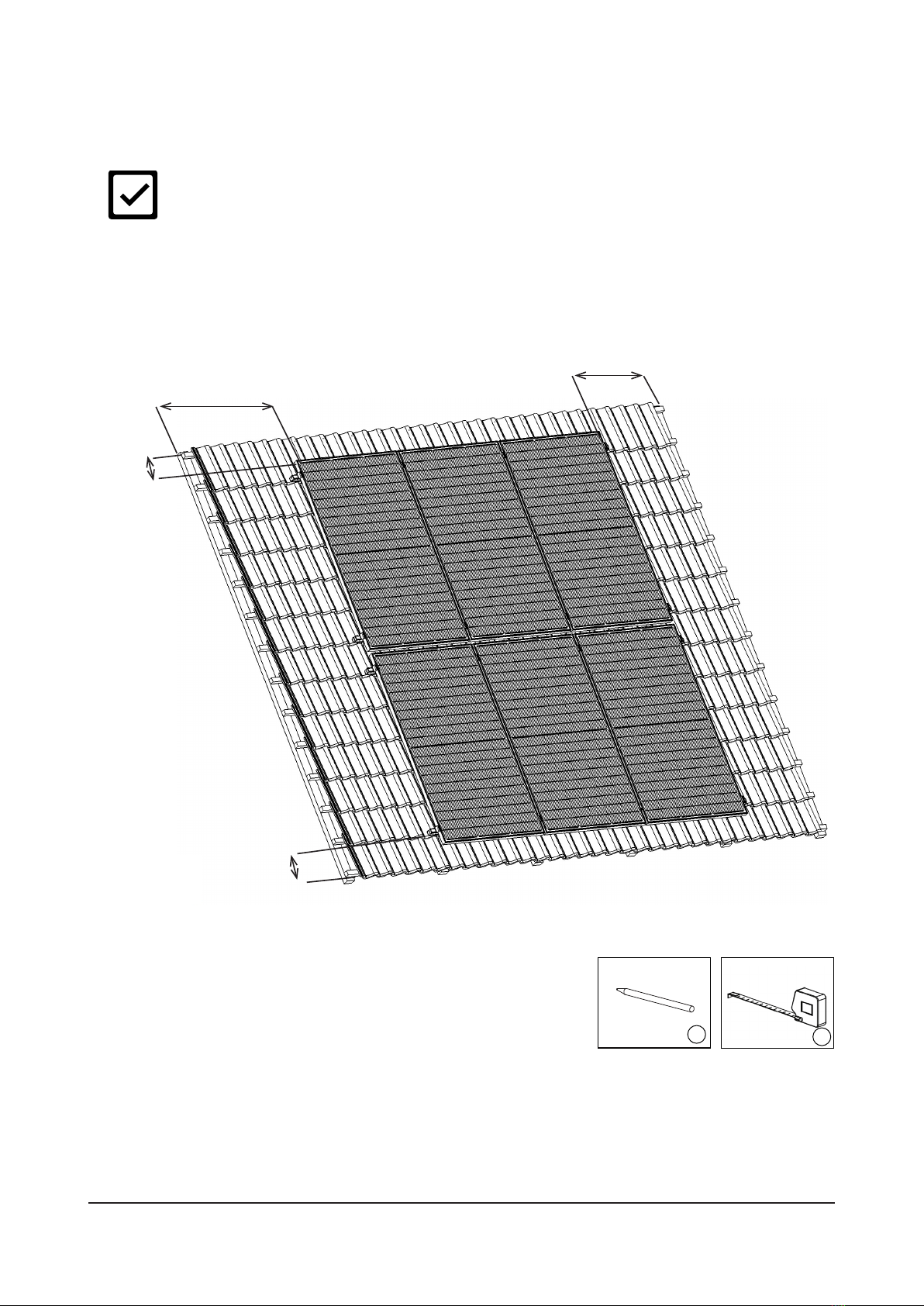
2.4 Solar Panel Posion Guideline
ATTENTION! DO NOT install this system on a roof with pitch > 60 degrees.
The minimum clearance of solar panels from the roof edges, guers and ridges is typically 30cm (please check with
your local building regulaons).
> 30cm
> 30cm
> 30cm
1
2
3
4
5
6
or
S10 S10
Scaold or stable safe
ladder
Tape measure Brush Ratchet with hexagon Battery-operated drill
Felt-tip pen/chalk Mounting wedge/keg
BC
10 R6 mounting system (Portrait and landscape)
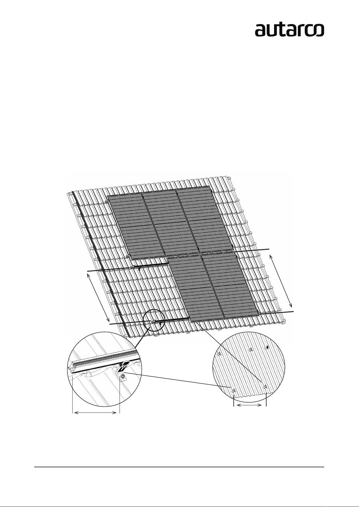
2.5 Hooks and Rails Posion Guideline
Before proceeding with the installaon, make sure the hooks and rails are installed according to the dimensions
given below. This can be dierent per product:
• The maximum distance between two successive hooks (H1) is 120cm, but typically 60-80cm.
Refer to our calculator for specic value
• The distance between rails (R2) is between 0.5 and 0.7 mes the length of the module (L). Please check
the allowed clamping posion in the Solar Panel Installaon Manual.
refer to the ‘Mounng’ secon of your modules manual for module-specic values
• The maximum rail overhang distance (OH3) is 30cm.
The values for Hook Distance (H1) and Overhang Distance (OH3) are determined by wind zone, height of the
building and terrain code.
(L)
Length of
module
(R2)
0.5 x L to 0.7 x L
(OH3)
(H1)
installation manual
11
R6 mounting system (Portrait and landscape)
3. Installaon
Exploded view of the R6 Mounng System. See pages 7 and 8 for component numberings.
An overview of the installaon steps for the R6 Mounng System in exact order:
3.1 Marking the posion of mounng hooks
3.2 Mounng hooks onto the roof
3.3 Aaching rails onto the hooks
3.4 Clamping modules into the rails
3.5 Installaon complete
5
5
6
6
2
2
1
4
4
7a 4
27a
7a
7a
7a

12 R6 mounting system (Portrait and landscape)
3.1 Marking the posion of mounng hooks
Step 1 – Measure and idenfy the posion of the mounng hooks using a measuring tool C.
see secon 2.5 (pg 10) for the reccommended hook (H1) and rail (R2) distances
Step 2 – Use a chalk or marker pen B to mark the roof le that will be removed for mounng. This is the le
directly above the le that the hook mounts onto.
installation manual
13
R6 mounting system (Portrait and landscape)
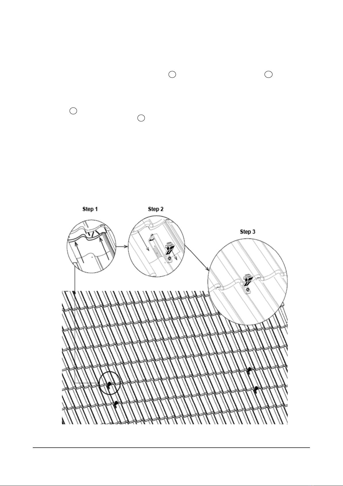
3.2 Mounng hooks onto the roof
We oer various types of roof hooks depending on raer, baen and le specicaons. In this manual we illustrate
the installaon procedure for the M2.AR6THX1.1 Hook 7a and M2.AR6THX1.1 Screwed Hook 7b .
Step 1 – Remove the roof les marked in 3.1, by sliding it upwards and under the roof le immediately above
it.
For THX1 Hook 7a
Step 2– Fit the M2.AR6THX1.1 Hook 7a onto the trough of the roof le (downward curve of the le). The
hook should secure both the roof le and the baen.
Step 3 – Slide the removed roof le back in place.
14 R6 mounting system (Portrait and landscape)
Orientaon of the hooks
Step 1 - Adjust the orientaon of the bracket portrait or landscape by unghtening the screw and reposioning
the bracket before reghtening the screw
Step 2 - Place your rail over the bracket aachement
Step 3 - Adjust the height of the bracket aachement
Step 4 - Push down on the rail unl you hear a click
Step 5 - Tightent the screw on the aachement
installation manual
15
R6 mounting system (Portrait and landscape)
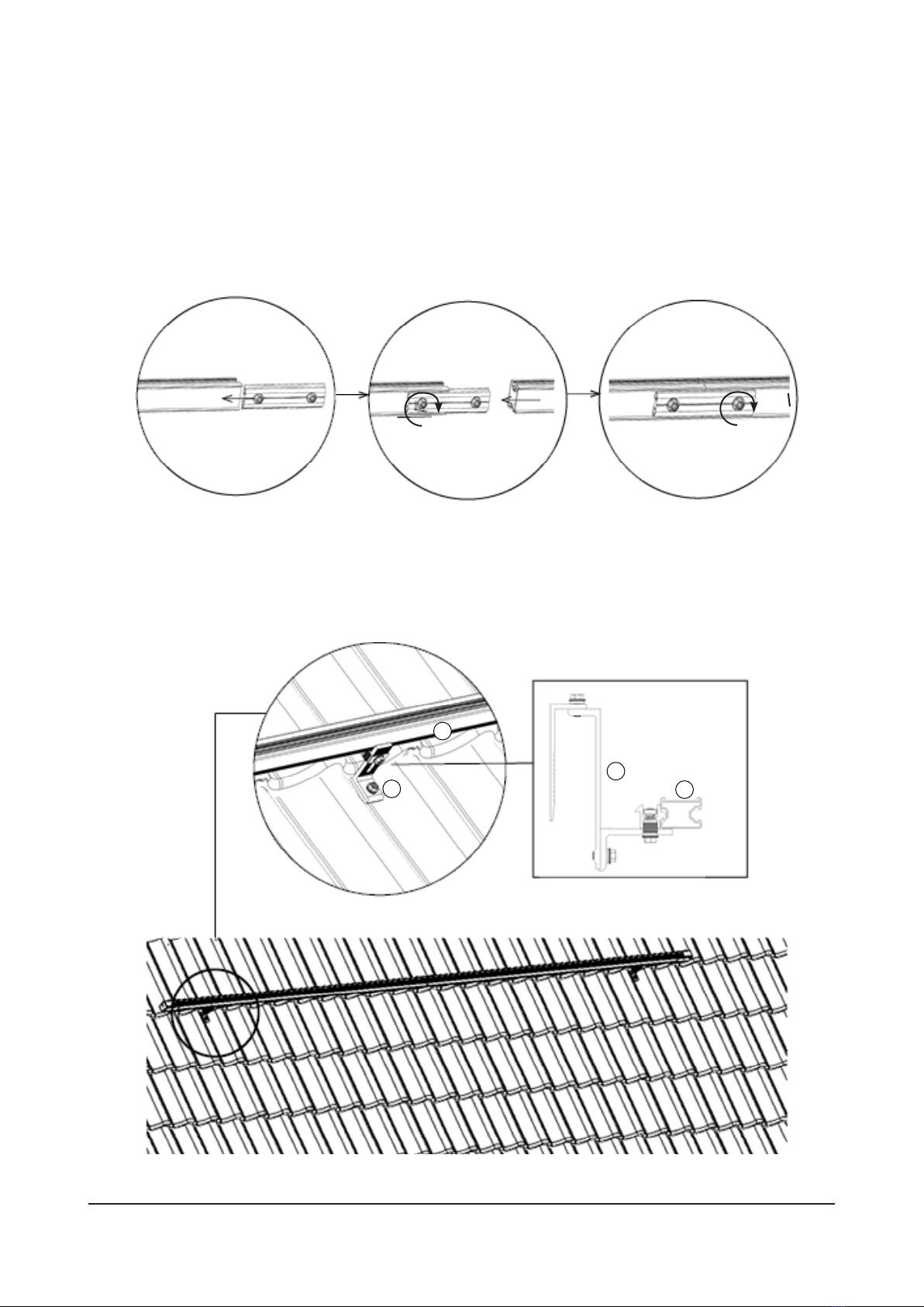
3.3 Aaching rails onto the hooks
Step 1 – Connect two or more R6 rails by sliding one extremity of the rail splice in the rail channel.
Step 2 – Tighten the screw to anchor to the rail
Step 3 – Slide the second rail over the other extremity of the rail splice
Step 4 – Tighten the second screw to secure the second rail in place
Step 5 – Adjust the orientaon of the bracket by unghtening the screw and reposioning the bracket before
reghtening the screw.
Step 6 – Place your rail over the bracket aachement and adjust the height of the bracket aachement.
Step 7 – Push down on the rail unl you hear a click.
Step 8 – Tightent the screw on the aachement.
7
7
Step 1 Step 2 and 3 Step 4
2
2

16 R6 mounting system (Portrait and landscape)
3.4 Clamping modules into the rails
3.4.1 How to assemble clamps onto the rails
End clamps 5and middle clamps 6can be easily ‘snapped’ into the rails using the steps given below. We use the
middle clamp 6 in this illustraon, but the steps are exactly the same for end clamps 5.
Step 1 – Hinge both legs of the clamp into the rail.
Step 2 – Press rmly down to snap the hinged legs in place.
Step 3 – Slide the clamp into the desired posion on the rail and screw bolt to x posion.
3.4.2 Anchoring the rails (portrait & landscape):
Step 1 – Adjust the orientaon of the bracket portrait or landscape by unghtening the
screw and reposioning the bracket before reghtening the screw
Step 2 – Place your rail over the bracket aachement
Step 3 – Adjust the height of the bracket aachement
Step 4 – Push down on the rail unl you hear a click
Step 5 – Tightent the screw on the aachement
Step 1 Step 2 Step 3
5or 6
5or 65or 6
2
22
5

installation manual
17
R6 mounting system (Portrait and landscape)
3.4.3 Installing rst module onto the rails with end clamps
Step 1 – Assemble the end clamps 5(see 3.4.1) into the R6 rails 2. Make sure less than 4cm rail is protruding
outwards from the end clamp.
Step 2 – Posion the solar module 1in portrait on the rails and align against the end clamps 5.
Step 3 – Tighten the screws preassembled on the end clamps 5to x the solar module 1onto the rails.
Step 4 – Slide the end caps 3into the the rail to secure the end clamps 5.
use the wire slot on the rail to tuck away any wires or cables (Fig. 1)
5
5
5
5
11
1
4
< 4cm
Step 2 Step 3
Step 4
Figure 1
Step 1
5
5
4

18 R6 mounting system (Portrait and landscape)
3.4.4 Installing modules onto the rails with middle clamps
Step 1 – Assemble the middle clamps 6 (see 3.4.1) into the R6 rails and slide the middle clamps le to align
with the adjacent module 1. Do not ghten the clamps yet.
Step 2 – Posion the solar module 1in portrait on the rails and align against the middle clamps 6.
Step 3 – Tighten the preassembled screws on the middle clamps 6to x the solar module 1onto the rails.
Step 4 – Repeat steps 1 to 3 unl the nal solar module along the rails is installed.
61
1
1
1
11
6
6
Steps 1 to 2 Step 3

installation manual
19
R6 mounting system (Portrait and landscape)
3.4.5 Securing nal module with end clamps
Step 1 – Assemble the end clamps 5 (see 3.4.1) into the R6 rails and slide the end clamps le to align with
the nal module 1.
Step 2 – Tighten the screws preassembled on the end clamps 5to x the solar module 1onto the rails 2.
Step 3 – If the rail is protruding outwards more than 4cm from the end clamp, saw o the excess rail.
Step 4 – Slide the end caps 3into the the rail to secure the end clamps 5.
55
3
1
1
Step 3 Step 4
Step 1 and 2
1

20 R6 mounting system (Portrait and landscape)
3.5 Installaon complete
Repeat installaon secons 3.4.2 to 3.4.4 to complete remaining rows of rails.
The installaon is now complete!
4. Disposal
To comply with European Direcve 2002/96/EC on waste Electrical and Electronic Equipment
and its implementaon as naonal law, electrical equipment that has reached the end of
its life must be collected separately and returned to an approved recycling facility. Ignoring
this EU Direcve may have severe eects on the environment and your healt.
Other manuals for Apex R6
1
Table of contents


