Autarco 3P User manual

Installation Manual
3P Smart Meter
IM-S2.3P-SMARTMETER-EN-V1.2

Contact Information
Autarco Group B.V.
Torenallee 20
5017 BC Eindhoven
The Netherlands
www.autarco.com
info@autarco.com
Other Information
This manual is an integral part of the unit. Please read the manual carefully before installation, operation or
maintenance. Keep this manual for future reference.
Product information is subject to change without notice. All trademarks are recognized as the property of
their respective owners.
© Autarco Group B.V.
All rights reserved.
IM-S2.3P-SMARTMETER-EN-V1.2
2

Installation manual
Table of Contents
1. Introduction 4
1.1 Read this first 4
1.2 Target Audience 4
1.3 Intended Application 5
2. Preparation 5
2.1 Safety instructions 5
3. Overview 5
3.1 Front Panel Display 6
4. Installation 7
4.1 Mounting the Consumption meter 7
4.2 Electrical Connections 7
4.3 Wiring 8
4.4 Monitoring 9
5. Specifications 10
IM-S2.3P-SMARTMETER-EN-V1.2
3

1 Introduction
1.1 Read this first
The main purpose of this user manual is to provide instructions and a detailed description of procedures
for installing, operating, maintaining and troubleshooting the Autarco 3-phase (3P) smart meter used with
Autarco inverters. Always keep this user manual available at all times.
1.2 Important symbols
To reduce the risk of electrical shock, and to ensure the safe installation and operation, the following safety
symbols appear throughout this document to indicate dangerous conditions and important safety
instructions.
WARNING! Indicates safety instruction, which if not correctly followed, can result in injury
or property damages.
RISK OF ELECTRIC SHOCK! Indicates safety instructions, which if not correctly followed,
could result in electric shock.
HOT SURFACE! Indicates safety instructions, which if not correctly followed, could result
in burns.
1.3 Target Audience
This manual is intended for anyone who installs or maintains Autarco inverters in conjunction with a
3-phase consumption meter (smart meter). Before any further action, the operators must first read all
safety regulations and be aware of the potential danger to operate high-voltage devices. Operators must
also have a complete understanding of this device’s features and functions.
ATTENTION! Qualified personnel means a person with valid license from the local authority in:
●Installing electrical equipment and PV power systems (up to 1000 V).
●Applying all applicable installation codes and using Personal Protective Equipment.
●Analyzing and reducing the hazards involved in performing electrical work.
WARNING! Do not use this product unless it has been successfully installed by qualified personnel in
accordance with the instructions in chapter 4 “Installation”.
IM-S2.3P-SMARTMETER-EN-V1.2
4

Installation manual
1.4 Content of package
3P smart meter
(3-phase consumption meter)
Brand: ACREL
Type: DTSD1352
3 CT clamps
RS485-cable
+ comm-connector
+ RJ45-connector
1.5 Intended Application
This manual applies to the following products;
●S2.3P-SMARTMETER Consumption meter for 3 phase inverters
All current inverter models have the possibility of internal power export limitation using an external
current clamp or consumption meter. The internal power export limitation (EPM) is only applicable for
systems with one inverter. Please read the relevant inverter series manual for more information. External
power export limitation with more than one inverter is possible using the external PELD. This is possible
with all inverters.
IM-S2.3P-SMARTMETER-EN-V1.2
5

2 Preparation
2.1 Safety instructions
DANGER! Do not touch any internal components whilst the inverter is in operation.
NOTICE! Do not directly connect AC output of the inverter to any private AC equipment. The PV
inverter is designed to feed AC power directly into the public utility power grid.
WARNING! The installation, service, recycling and disposal of the inverters must be performed by
qualified personnel in compliance with national and local standards and regulations.
Please contact your dealer to get the information of an authorized repair facility for any maintenance
or repairmen.
Any unauthorized actions including modification of product functionality of any form will affect the
validation of warranty service; Autarco may deny the obligation of warranty service accordingly.
IM-S2.3P-SMARTMETER-EN-V1.2
6

Installation manual
3 Overview
3.1 Front Panel Display
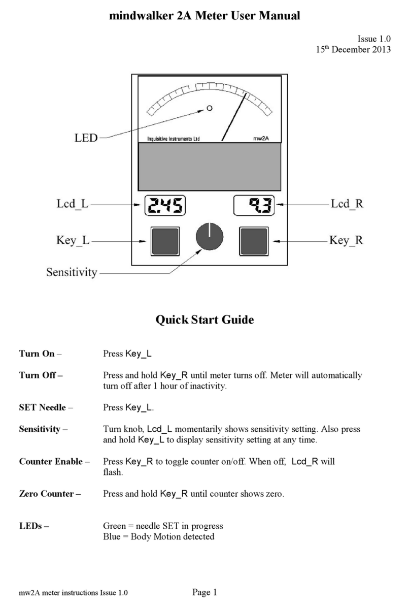
Figure 3.1: Front panel display
IM-S2.3P-SMARTMETER-EN-V1.2
7

4 Installation
4.1 Mounting the smart meter
The consumption meter needs to be installed in the meter cupboard and can be installed on a 35mm DIN
rail.
4.2 Electrical Connections
IM-S2.3P-SMARTMETER-EN-V1.2
8

Installation manual
4.3 Wiring
Install the current clamps (CT clamps) on the phase cables that directs to the grid. Note the arrow on the
current clamp and make sure it is installed in the right direction.
Use port 21 and 22 on the meter to connect it to the meter port of the inverter.
IM-S2.3P-SMARTMETER-EN-V1.2
9

4.4 Settings
It is possible that the CT ratio of the meter needs to be set up correctly, this also needs to be done if you
choose to use different CT clamps.
1. Press SET button to enter the Main Menu and get in “PASS” interface
2. Press Enter to show “0000”, and enter the code 0001
3. Press Enter and navigate to In. > Transformer settings >CT
4. Adjust CT ratio to correct value
5. Press Enter
6. Press Set x 2 times
7. Press Enter to save
8. Press Down to change to Yes
9. Press Enter to save
The CT ratio needs to be set to 30 if you use the delivered CT clamps.
4.5 Monitoring
In order to get consumption data, a WIFI-STICK-D, LAN-STICK-D or GPRS-STICK-D (one of our ‘D’ sticks,
either digital sticks) needs to be used, and settings on the inverter need to be changed.
Use the up and down buttons on the inverter to navigate through the menu.
NOTE! The access to this area is for fully qualified and accredited technicians only. Enter
menu “Advanced Info’ and “Advanced Settings” (password needed).
●Go to Advanced settings
●Enter password (contact Autarco Support for instructions)
●Select 24h Switch
●Set to ON and press ENTER
●Go to Internal EPM set -> Mode Select
●Select Consumption Monitor and press ENTER
IM-S2.3P-SMARTMETER-EN-V1.2
10

Installation manual
5 Specifications
Model name
S2.3P-SMARTMETER
Grid topology
3P+N
Rated voltage
3 x 230V/400V
Input current
3 x 1 (6) A (via CTs)
Operating temperature
-25°C - 55°C
Relative humidity
<95% (non-condensing)
Dimension (L*W*H)
127L*70W*89H (mm)
IM-S2.3P-SMARTMETER-EN-V1.2
11
Table of contents
Other Autarco Measuring Instrument manuals

