AUTEC ASG-3005 User manual
INSTALLATION-MANUAL
Scissor
ASG-3005
ASG-4005
ISSUED 11-02-04
AUTEC Hefbruggen bv
•Wheelfree scissorlifts –electro hydraulic
INDEX OF CONTENTS PG.
1. Introduction 02 2. Packing, transport and storage 02
3. Safety specifications 02 4. Description of the lift 02
5. Installation 03
Industrieterrein IJsselveld, Vlasakker 11, 3417 XT MONTFOORT, The Netherlands
Tel: +31 348 477000 Fax: +31 348 475104 Internet: www.autec.nl - E-mail: info@autec.nl
en/TD-ASG-4005-1
INSTALLATION-MANUAL
Scissor
ASG-3005
ASG-4005
ISSUED 11-02-04
AUTEC Hefbruggen bv
6. Connection to electrical mains
7. Safety checks
8. Goods received report
9Electrical circuit diagram
10 Hydraulic system diagram
04
05
05
06
07
1. INTRODUCTION
CAUTION
This instruction manual is intended
for the assembly personnel who are
going to carry out the installation of
the lift.
2. PACKING, TRANSPORT
AND STORAGE
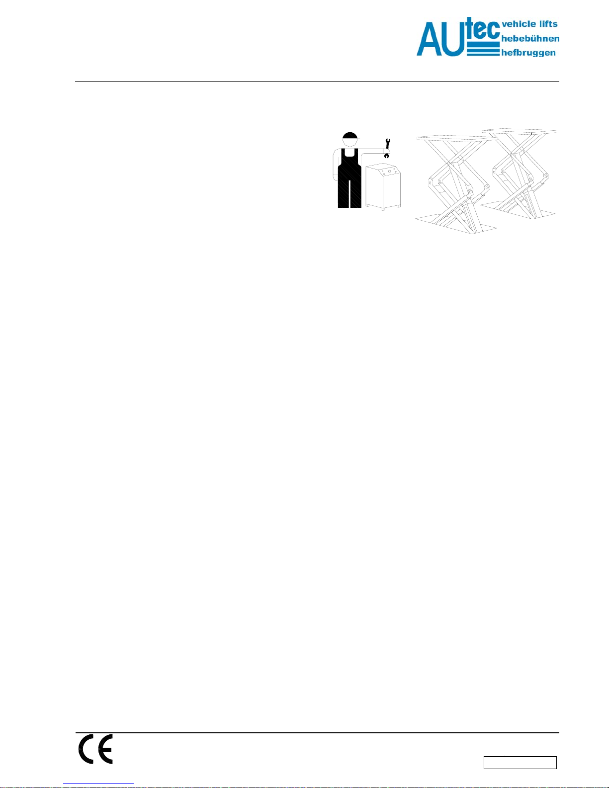
Every action involving the operation,
transportation or unpacking of the
equipment must only be done by
trained personnel who have a proper
knowledge of the lift, and who are
familiar with the contents of this
operating manual.
LIFTING AND MOVING THE
PACKING CRATES CONTAINING
THE EQUIPMENT
The wooden crates must be lifted and
moved with the help of a fork lift truck or
a lift crane. (Fig. 1)
Fig. 1
The equipment chosen must be
capable of lifting and moving the
equipment safely, keeping in mind
the dimensions of the vehicle, the
weight, the centre of gravity and
projecting and fragile parts.
STORAGE
The packed lift must always the placed
in a covered area at a temperature
between -10 oC and + 40 oC and must
not be exposed to direct sunlight.
OPENING THE CRATES
Check whether the machine have been
damaged during transportation, and
whether all the components as
mentioned in the Packing List are
physically present.
REMOVAL OF CRATES
The wood of the crates may be re-used.
It is strongly recommended
that you should first carefully read
the safety instructions.
3. SAFETY REGULATIONS
The manufacturer hereby refuses to
accept any responsibility for injury to
persons or damage to equipment or
property if it appears that incorrect
handling of the lift has taken place. This
instructions manual only describes the
operating- and safety aspects which
persons who are installing the machine
need to know. In order to understand
the terminology used in this manual, it is
necessary that the person performing
the installation work should have
specific experience in industrial work,
service, maintenance and repair
activities, and must also possess the
ability to explain the drawings and the
descriptions contained in this manual to
other people. At the same time he must
also be aware of the general and
specific safety regulations which apply
in the country where the lift is being
installed.
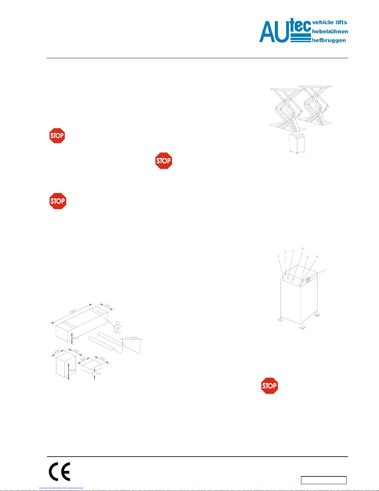
4. DESCRIPTION OF THE LIFT
(Fig.2)
The lift consists of the following :
Two lifts and two base frames the base
frames are fitted to the ground with the
help of wedge bolts. The vehicle to be
lifted is placed on four rubber support
plates which are supplied along with the
machine. The lifts are capable of being
extended, so that cars with a longer
wheel base can also be mounted. Both
the lifting systems consist of lifting
arms, as well as hydraulic cylinders.
The movement of the cylinder is
transmitted to the arms. The lift is
operated over a control cabinet which is
anchored to the floor next to the
scissors lift.
Fig.2
CONTROL BOX (FIG.3)
The controlpanel of the controlbox
consists of the following:
1. Safety switch for completing the
lowering of the platform over the
last 400 mm of the descent
2. Voltage monitoring lamp
3. Horn/signal lamp
4. Emergency stop button
5. Lowering motion button.
6. Lifting motion button.
7. Main switch.
Fig.3
In the control panel, there is a hydraulic
part, which consists of an oil tank, a
hydraulic pump and electrical motor,
solenoid valves and hydraulic hoses
5. INSTALLATION
Installation may only be done
by persons authorised to do so.
BEFORE STARTING INSTALLATION,
PLEASE RECHECK ALL THE
CONTROL POINTS.
The lift must be installed in an enclosed
space where weather influences do not
have any effect. The place of installation
must be at a sufficient distance from the
Industrieterrein IJsselveld, Vlasakker 11, 3417 XT MONTFOORT, The Netherlands
en/TD-ASG-4005-2

INSTALLATION-MANUAL
Scissor
ASG-3005
ASG-4005
ISSUED 11-02-04
AUTEC Hefbruggen bv
storage locations of paint and wax, and
also rooms where there is a danger of
explosion.
ELECTRICAL POWER SUPPLY
POINT.
The client must ensure that there is a
power supply point near the installation
site, which satisfies all the applicable
legal requirements (see page 4). If such
power supply is not available, the
installation technician will arrange for
an emergency cable. The lift shall be
tested after the emergency power
supply has been dismantled. The client
must then arrange for a duly qualified
and recognised installation technician to
lay the final wiring.
IMPORTANT INSTALLATION
MEASURES
The lift must be installed taking into
account the dimensions of other objects
(Fig. 4), and the rules and regulations
applicable in the country where the lift is
installed.
In particular, attention should be paid to
the following :
The minimum height from the floor,
at the installation location, must be
5000 mm
The minimum distance from the
walls must be 1 m.
The minimum working area is 500
mm
Industrieterrein IJsselveld, Vlasakker 11, 3417 XT MONTFOORT, The Netherlands
en/TD-ASG-4005-3
Adequate room for working
Adequate room for maintenance,
access-/ and exit routes.
Position with respect to other
machines
In the neighbourhood of the power
supply point to ensure problem-free
connection.
Fig. 4
LIGHTING
All the parts of the lifting lift must be
uniformly and adequately lighted.
During the installation work,
there must be no unauthorised
persons in the safety zone around
the lift (Fig. 4).
INSTALLATION OF THE LIFT
Take the two parts of the lift out of the
packing case. Seal the hydraulic hoses
openings with tape in order to prevent
the contamination of the hoses. To
move the vehicle loading tracks, one
must use a lifting vehicle having
sufficient lifting capacity. Lower the lift
onto the desired installation location.
Fig. 5
Lift the lifting tracks with the help of a
crane to a height of around 800 mm and
place the lift in its interlock.
Fig. 6
CONNECTING THE HYDRAULIC
SYSTEM (see figure 20)
Put the control cabinet in the selected
spot. Please keep in mind the minimum
distance to be maintained with respect
to other objects. Open the control
cabinet with the help of a socket
wrench. The connections to the
connecting block (Fig. 7) in the control
panel, and the hydraulic system hoses
are marked. Connect the hydraulic
hoses according to the following
drawing. Thereafter firmly tighten the
connections.
Fig. 7
Ref.A
Fig. 8
6. CONNECTING TO THE
MAINS
WARNING
The following actions must only be
carried out by duly authorised
personnel :
First check the following points before
connecting to the mains:
INSTALLATION-MANUAL
Scissor
ASG-3005
ASG-4005
ISSUED 11-02-04
AUTEC Hefbruggen bv
Industrieterrein IJsselveld, Vlasakker 11, 3417 XT MONTFOORT, The Netherlands
en/TD-ASG-4005-4
-
-
-
-
The electrical system at the
workplace must be protected
according to the applicable
standards.
The wires must be of the following
sizes : in the case of 400 V they
must be at least 2.5 mm2fuse max
16A. In the case of 230V 3-phase
supply, the wire size must be at
least 4 mm2.
The supply cable must be provided
with an earthing wire, and must be
suitable for a firm and final
connection.
Connect the power supply cable to
the control cabinet according to
Fig. 15.
Put the main switch in the “1” position.
Check the direction of rotation of the
motor by pressing the lifting-motion
button. The direction of location must be
anti-clockwise.
FILLING THE HYDRAULIC SYSTEM
Fill the hydraulic system with around 15
litres of hydraulic oil which satisfies the
standard ISO 6743/4 :For example Fina
Hydran TS32 or an equivalent oil.
Test Properties Value
ASTM
DF1298 Density at 20°C 0.8Kg/l
ASTM
D 445 Viscosity at 40°C 32cSt
ASTM
D 445 Viscosity at
100°C 5.43 cSt
ASTM
D 2270 Viscosity index 104 N°
ASTM
D 97 Freezing point -30°C
ASTM
D 92 Flame point 215°C
ASTM
D 644 Neutralisation
number 0.5 mg
KOH/g
DE-AERATE THE HYDRAULIC
SYSTEM
•
•
Put the main switch in the “1”
position.
Keep the button 1 in the control
cabinet on the underside of the
control panel (fig. 9) and the lifting
button (2) pressed until both the
lifts are in their highest position.
Hold both the buttons down for at
least 20 seconds. Now fill the oil
tank once more to a height of 5
meters.
Fig. 9
CONNECTING THE PNEUMATIC
SYSTEM (Fig.17 )
The pneumatic system to which the lift
is connected must have a water
separator and lubrication system as well
as a pressure reduction valve.
Raise the lift to its highest position.•
•
•
•
•
•
•
•
•
Connect the pneumatic hoses to
the connecting points in the control
cabinet according to figure 17.
Now connect the compressed air to
the pneumatic valve.
Check the system for proper
functioning. You can do this by
pressing the lowering-motion
button : the pneumatic protection
will thereby be removed.
Lower the lift fully.
Once more carry out the airing
procedure.
Put the panels back into the control
cabinet.
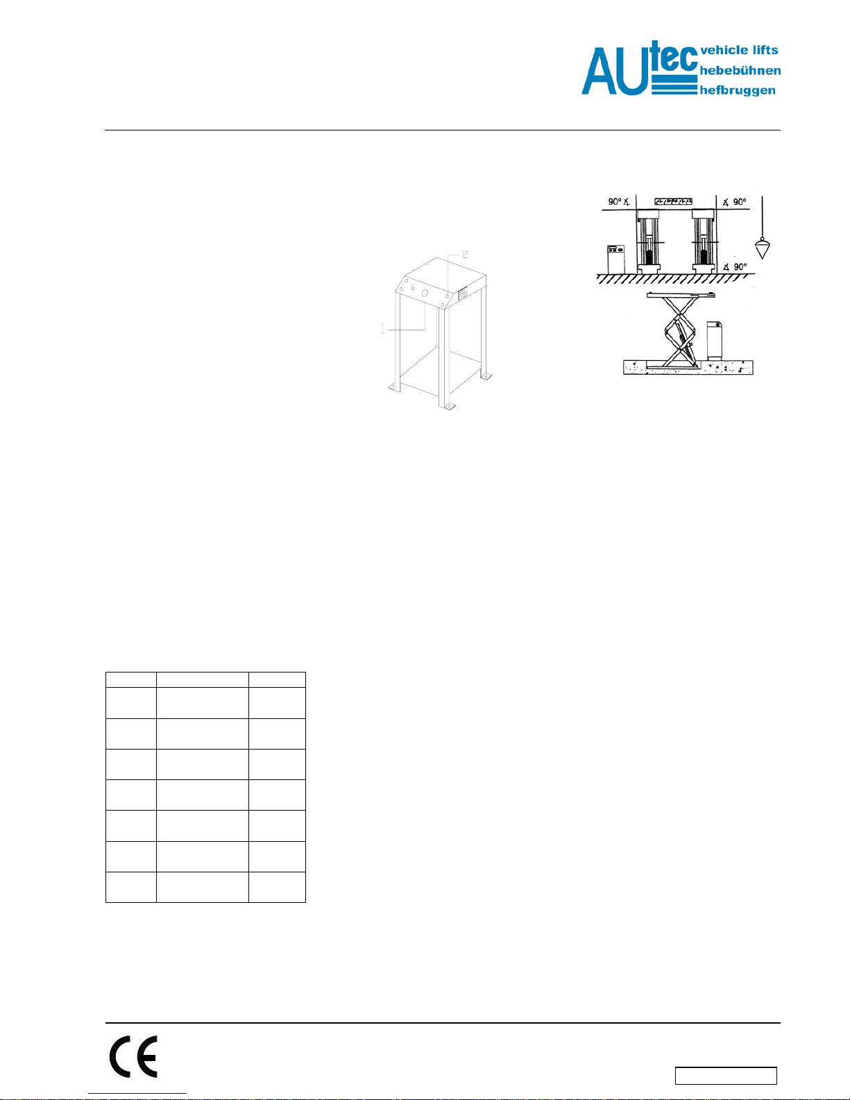
ALIGNING THE LIFT (Fig. 10)
Raise the lift to height of about 1.6
meters (check whether the
pneumatic-mechanical lock is
working).
Check whether the vehicle-
uploading plates are properly
aligned vertically and horizontally
with respect to the floor and each
other (Figure 10). This is
extremely important for the proper
functioning of the lift. If necessary,
insert packing shims under the
base frame to ensure proper
alignment.
Fig. 10
CHECK THE PHOTO CELL
Check whether the photocell
synchronisation guard is correctly
installed, for which you may proceed as
follows :
1. Raise the lift to height of
approximately 1 meter.
2. Cut out a piece of paperboard of
the dimensions 100x100mm, with a
25 mm hole in the middle.
3. Place the carton in the middle of
the reflection mirror.
4. Now press the lifting-motion button.
5. If the lift does not rise, it means
that the lift is not properly aligned.
6. Aligned the lift once again.
FIXING THE LIFT
The lift can be fixed in two ways,
depending on cassette selected:
1. Open cassette: Using a concrete
drill, bore holes of 12 mm and 125
mm depth in the floor. Use the
frame of the lift as a template.
Hammer in wedge bolts of the type
TIKM12x100 into the floor see ref.
2 Fig 11. Tighten the wedge bolts
using a torque wrench with a
torque of 45 Nm.

INSTALLATION-MANUAL
Scissor
ASG-3005
ASG-4005
ISSUED 11-02-04
AUTEC Hefbruggen bv
1
2
Fig. 11
Industrieterrein IJsselveld, Vlasakker 11, 3417 XT MONTFOORT, The Netherlands
en/TD-ASG-4005-5
2. Closed cassette : Screw M12x25
bolts in the tapped holes made for
the same. Tighten the bolts with a
torque of 80 Nm.
HEIGHT OF SETTING BOLTS
(REF. 1 FIG. 11)
Set the bolts in such a manner that the
upper edge of the vehicle-uploading
plates in the lowest position are level
with the floor.
LIMIT SWITCHES
The functions of the various limit
switches are as follows :
1. Limit switch : This is for the
lowering-motion in the last 40 cm.
2. The synchronisation switch
ensures the synchronisation of the
two lifts.
3. The lifting-motion limit switch limits
the lifting-motion.
4. Photocell for synchronisation
protection.
Check the working of the limit
switches.
The limit switches are pre-assembled in
the factory. Check to see whether the lift
gets limited at a height of 1850 mm. If
not, turn the lifting-motion cam ring to
the correct position (Fig. 12).
Check whether the lowering-motion limit
switch is so adjusted that the lift stops at
a safety height of 400 mm. If not, turn
the lowering-motion cam ring to the
correct position.
Caution : While rising to its maximum
position, the lifting-motion proximity
switch is in contact with the cam. At its
maximum working height, the proximity
switch loses contact with the cam, and
the lift will thereby get disconnected.
Caution : While rising to its maximum
position, the lowering-motion proximity
switch is in contact with the cam. At the
safety working height of 400 mm, the
proximity switch detects the cam, and
the lift will thereby get disconnected.
Fig. 12
SYNCHRONISATION SWITCH
(FIG. 13)
The synchronisation switch mounted on
the underside of the lift must be
installed in such a manner that in the
lowest position of the lift, it is 1 to 3 mm
away from the metal plate, see ref. 1
Fig. 13
1
Fig. 13
Monitoring the motion of the lift
without load :
Raise and lower the lift 2 or 3 times
without load, and check whether :
•
•
•
•
•
The lift stops at the maximum
height
Whether the lifting-motion limit
switch is working properly.
Whether the lowering-motion limit
switch is working properly
Whether the synchronisation
switch is working properly (the lifts
must get lifted and lowered
simultaneously).
Whether the lowering-motion signal
is working properly.
Monitoring the motion of the lift with
load :
Check the above points once more, but
this time with a vehicle mounted on the
lift.
7. SAFETY CHECKS
After the complete installation of the lift,
the responsible installation engineer
must check all the safety arrangements
on the lift to check whether they are
working properly.
CLEANING OF THE LIFT (Fig. 17)
The installation engineer responsible
must take care to see that the lift which
is installed is delivered to the client in a
'squeaky clean' condition.
Fig. 17
8. GOODS RECEIPT REPORT
The concerned installation engineer
must prepare a goods receipt report
after completion of the installation. The
goods receipt report must be prepared
as carefully as possible. Any complaints
and/or observations of the client will
also be noted in the report under the
heading ‘Remarks’. The report must be
signed by the responsible installation
engineer, and by the client. The
installation engineer will deliver the
report to the technical department. The
installation engineer must see to it that
the report are filled-in in time in the
service box.
This manual suits for next models
1
Table of contents
Other AUTEC Scissor Lift manuals


