AUTEC ASLP-3005 User manual

USER MANUAL
Scissor
ASLP-3005
ASLP-3005/IG
ISSUED 04-02-2004
AUTEC Hefbruggen bv
Industrieterrein Ijsselveld, Vlasakker 11, 3417 XT MONTFOORT, The Netherlands
•Wheel-free electro-hydraulic lifts
en/TA-ASLP-3005-01

USER MANUAL
Scissor
ASLP-3005
ASLP-3005/IG
ISSUED 04-02-2004
AUTEC Hefbruggen bv
Industrieterrein Ijsselveld, Vlasakker 11, 3417 XT MONTFOORT, The Netherlands
INDEX OF CONTENTS PAG
1Introduction 02
2How to use this manual 02
3Description of the lift 02
4Technical specifications 03
5Safety 03
6Controls and operation 05
7Maintenance 06
8Troubleshooting 07
9Conformity declaration 08
1. INTRODUCTION
CAUTION
This Manual is intended for factory
personnel who are going to operate
the lift; read the Manual before you
use the platform in any way or
perform any actions on it. This
Manual contains important
information about the following
points :
n THE PERSONAL SAFETY OF THE
OPERATOR
n PREVENT DAMAGE TO THE LIFTS
n PREVENT DAMAGE TO THE
VEHICLE
2. HOW TO USE THIS MANUAL
The Manual forms part of the lift and
must be available for reference in the
immediate vicinity of the lift at all times.
The operator of the lift must be able to
refer to the Manual quickly and at any
given moment.
IT IS STRONGLY RECOMMENDED
THAT YOU SHOULD FIRST
CAREFULLY READ THE SAFETY
INSTRUCTIONS.
The manufacturer hereby refuses to
accept any responsibility for injury to
persons or damage to equipment or
property if it appears that incorrect
handling of the lift has taken place. This
instructions manual only describes the
operating-and safety aspects which
persons who are installing the machine
need to know. In order to understand
the terminology used in this manual, it is
necessary that the person performing
the installation work should have
specific experience in industrial work,
service, maintenance and repair
activities, and must also possess the
ability to explain the drawings and the
descriptions contained in this manual to
other people. At the same time he must
also be aware of the general and
specific safety regulations which apply
in the country where the lift is being
installed. The word “operator”, which
has been used throughout this manual,
refers to a person who is authorised to
use the platform. The minimum legal
age for using the lift is 18 years.
3. DESCRIPTION OF THE LIFT
(see Fig. 1)
The electro hydraulic lift model ASLP-
3005, is anchored to the ground, and is
designed and manufactured for lifting
passenger cars and delivery vanes and
to hold them in a certain lifted position.
The main components of the lift are :
n Welded floor frame
n Movable parts (supports and arms)
n Lifting components
n Control cabinet
n Safety arrangements.
Fig. 1
See Fig. 2 for the following terms :
1. Operating side :the area in which
the operator does his work, and
from where he can access the
control cabinet.
2. Rear :The side where the support
extension pieces are mounted.
3. Front :The side where the cylinder
rod is mounted on the frame.
4. Sliding direction : Direction in
which the vehicle will come sliding
in, with the motor-side of the vehicle
in the front.
Fig. 2
CONTROL CABINET (Fig. 3)
The electrical control cabinet consists of
the following :
1. Safety switch for completing the last
400 mm of the lowering motion
2. Voltage monitoring lamp
3. Signal lamp/horn
4. Emergency stop button
5. Downward motion button
6. Lifting motion button
7. Main switch
Fig. 3
There is a hydraulic part in the control
cabinet which consists of an oil tank, a
hydraulic pump, an electrical motor,
solenoid valves and hydraulic hoses.
These include the following :
n Limit switches
n Electrical safety arrangements
n Overpressure valves
n Hose rupture protection
en/TA-ASLP-3005-02

USER MANUAL
Scissor
ASLP-3005
ASLP-3005/IG
ISSUED 04-02-2004
AUTEC Hefbruggen bv
Industrieterrein Ijsselveld, Vlasakker 11, 3417 XT MONTFOORT, The Netherlands
4. TECHNICAL SPECIFICATIONS
ASLP-3005
LIFTING CAPACITY : 3.000 kg
Lifting time : 45 sec
Lowering time : 45 sec
Total weight : 700 kg
Noise level : 74-dB(A)/1m
Working temperature : -10oC / +40oC
Working environment : covered
Dimensions : Fig. 4
ELECTRICAL MOTOR ASLP-3005
Motor power : 3.0 KW
Voltage: 230V/400V(3-Ph). +/-5%
Frequency : 50 Hz
Amperage : 230V: 13.5 A
400V: 7.8 A
No. of wires : 4
Speed : 1400 rpm
Fig. 4
THE WEIGHT OF THE VEHICLE
The lift can be used for practically all
vehicles provided that the maximum
loading capacity is not exceeded.
MAXIMUM DIMENSIONS OF THE
VEHICLE TO BE LIFTED (see Fig. 5)
Maximum breadth : 2200 mm
Maximum wheel base : 3000 mm
Keep in mind that low-slung cars (cars
with chassis close to the ground) do not
match with the lift structure. Take
particular care in case of low-slung
sports cars.
Fig. 5
Always keep in mind the lifting capacity
of the lift in the case of vehicles with
special characteristics (such as delivery
vans and other types of vans, etc.).
The safety zone (Fig. 6) is to some
extend determined by the
dimensions of the vehicle to be lifted.
Fig. 6
CHECK THE MAXIMUM LOADING
CAPACITY, THE MAXIMUM WEIGHT
AND THE DISTRIBUTION OF LOAD IN
THE CASE OF LARGE VEHICLES.
MAX.3000 kg ASLP-3005
5. SAFETY
It is important to read point number 5 of
this Manual properly since it contains
important information about the risks
which the operator of the lift will be
exposed to if the lift is not used
properly. In what follows, you will find
information about how to avoid
dangerous situations.
WARNING
The lift is designed and
constructed to lift vehicles
and to hold them in a certain
position in a covered working place. Any
other form of use is not permitted. In
short, the lift is not suitable for the
following purposes :
n Washing and spraying work.
n To be used as a device for applying
force.
n To be used as a goods lift.
n To be used as a jack or for lifting
vehicles for changing wheels.
The manufacturer hereby refuses
entertain any claims for damages
arising in connection with injury to
persons or damage to vehicle or other
property caused due to incorrect and/or
unauthorised use of the lift.
During lifting-and lowering movements,
the operator must be within the zone of
operation (1), as shown in Fig. 6. The
presence of any person in the safety
zone (2) is strictly forbidden. The
presence of persons under the vehicle
is only permitted if the vehicle is parked
in the lifted position.
USE THE LIFT ONLY IF ALL THE SAFETY
ARRANGEMENTS ARE WORKING
PROPERLY. IF THESE RULES ARE NOT
FOLLOWED, SERIOUS INJURY COULD
BE CAUSED TO PERSONS AS WELL AS
IRREPARABLE DAMAGE TO THE LIFT
AND THE VEHICLE ON THE LIFT.
GENERAL PRECAUTIONS:
•The operator is bound to follow the
regulations which apply in the
country in which these lifts are
installed.
In addition, the operator must :
•Always work in the operator area as
designated in the Manual.
•Never remove the protective guards
or dismantle or shut down the
mechanical, electrical or other types
of safety arrangements.
•Read the safety regulations relating
to the lift and take cognisance of the
safety information provided in this
Manual.
en/TA-ASLP-3005-03
USER MANUAL
Scissor
ASLP-3005
ASLP-3005/IG
ISSUED 04-02-2004
AUTEC Hefbruggen bv
Industrieterrein Ijsselveld, Vlasakker 11, 3417 XT MONTFOORT, The Netherlands
The following terms have been used in
this Manual to describe the various
types of risk :
DANGER : there is a direct possibility of
danger which could lead to serious
injury or death.
WARNING: this indicates situations
and/or actions which are unsafe and
could lead to injuries of various types
except death.
CAUTION :this indicates situations
and/or actions, which are unsafe and
could lead to light injuries to persons
and/or damage to the lift, the vehicle or
other properties.
RISK OF DAMAGE DUE TO
ELECTRICITY :Special safety
arrangements have been made on the
lift in places where the risks are very
high.
RISKS AND PROTECTIVE MEDIA
The risks to which the operator is
exposed when the vehicle is in a raised
position, together with the protective
media which have been installed, in
order to limit the possible dangers.
LONGITUDINAL AND LATERAL
MOVEMENTS OF THE VEHICLE.
Longitudinal and lateral movements
include the following : forward-and
backward movements of the load (the
vehicle). Lateral movements include
displacement of the vehicle to the left or
the right, particularly during the lifting
process. These movements can be
prevented by placing the vehicle
securely on the support arm rubbers (on
the car-jack support points).
WARNING
Do not move the vehicle when
it is on the platform. The
platforms and the rubber fittings
should only be removed at the lowest
lifting position, and when there is no
load.
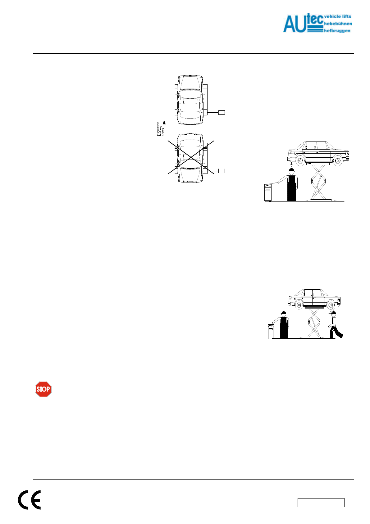
It is extremely important that the vehicle
is placed on the lift in such a manner
that there is an uniform distribution of
weight over the platforms (Fig. 7).
Please note that the motor side of the
vehicle must be placed on the side
which cannot be pushed out.
Fig. 7
To ensure the safety of persons and of
materials, you must see to it that :
n The safety zone is kept under
observation during the lifting
process.
n The motor of the vehicle is switched
off, that it is in gear, and that the
handbrake is also fully applied.
n The vehicle must be lifted on the
car-jack support points.
n Due account has been taken of all
the dimensions and weights.
RISKS INVOLVED IN LIFTING A
VEHICLE
The following safety arrangements have
been installed to prevent overloading
and damage :
n Limit switches limit the lifting and
lowering motion
n Overpressure valves protect the lift
against damage caused by
excessively high oil pressure.
n The hose rupture protection
arrangements prevent the platform
from sinking back to the original
position in case any hoses get
ruptured.
n The thermal protection cuts off the
power in case of overloading.
RISKS TO PERSONS
This paragraph describes the risks to
which the operator or any other person
near the working area where the lift is in
operation, in case the lift is not used in
the appropriate manner.
RISKS FOR THE OPERATOR (Fig. 8)
This risk arises in cases where the
operator is not standing at the
appointed place at the control cabinet;
when the lift with the vehicle is being
lowered, it is not permissible for the
operator to stand below the descending
system and its load to any extent. It is
imperative that the operator must be
standing in the operating zone during
the lifting and lowering operation.
Fig. 8
RISKS TO PERSONNEL
When the lift with the vehicle is moving
downward, it is not permissible for any
of the personnel to enter the room or
walk under the (downward) moving
parts of the lift.(Fig. 9)
The operator should not start the motion
of the lift until he has assured himself
that there are no persons within the
danger zone.
.
Fig. 9
CAUTION AGAINST COLLIDING ANY
PART OF THE SYSTEM
This is relevant in cases where the lift or
the vehicle are at head height. When
the lift is at standstill at a lower level, the
personnel should take care to see that
they do not bump into parts of the lift or
the vehicle. (Fig. 10).
en/TA-ASLP-3005-04

USER MANUAL
Scissor
ASLP-3005
ASLP-3005/IG
ISSUED 04-02-2004
AUTEC Hefbruggen bv
Industrieterrein Ijsselveld, Vlasakker 11, 3417 XT MONTFOORT, The Netherlands
Fig. 10
RISKS INVOLVED IN MOVING A
VEHICLE
Movements may be caused during
activities which involve the application
of an adequate amount of force for
moving the vehicle (Fig. 11). In cases
where the vehicle being lifted is almost
of the maximum permissible weight or
the maximum permissible dimensions,
movements in the vehicle could lead to
overloading or unbalancing.
Fig. 11
RISKS INVOLVED IN POSITIONING A
VEHICLE
This type of risk may arise if the vehicle
is not properly placed on the rubber
supports (Fig. 12), or if the platforms
are not properly aligned with respect to
the vehicle. One can avoid this by
always lifting the vehicle using the car-
jack support points, and to place the
vehicle as far as possible in the centre
of the platform.
Attention : while dismantling heavy
parts (for example the motor or shafts)
please note that the weight distribution
ratios change !
Fig. 12
Never rest any fittings or other objects
against the platform and never place
such objects under the platform when it
has a load mounted on it, since this can
impede the lowering operations and
may cause the vehicle to fall off the
platform (Fig. 13).
Fig. 13
Never enter the vehicle or start the
motor when the vehicle is on the lift
(Fig. 14).
Fig. 14
RISKS DUE TO INSUFFICIENT
LIGHTING The area surrounding the lift
must be properly lighted according to
the legal requirements applicable in the
place of installation.
RISKS OF USE/MAINTENANCE
Autec uses material of the highest
quality in its lift. These must be used
according to the standard specified, and
maintenance must be carried out
regularly.
RISK OF ELECTROCUTION
Never spray water or steam or solvents
or paint in the area immediately
surrounding the platform and the control
cabinet (Fig. 15).
Fig. 15
RISK OF SLIDING OUT
This risk can be overcome by avoiding
the spillage of oil or grease in the area
surrounding the lift (Fig. 16). Apart from
that, any oil spillage which may occur
should be thoroughly removed from the
spot.
Fig. 16
6. CONTROLS AND OPERATION
(Fig. 17)
The operating and control part consists
of :
1. Safety switch for lowering the last
400 mm
2. Voltage monitoring lamp
3. Signal lamp/horn
4. Emergency stop button
5. Lowering motion button
6. Lifting motion button
7. Main switch
Fig. 17
en/TA-ASLP-3005-05
This manual suits for next models
1
Table of contents
Other AUTEC Scissor Lift manuals


