AUTLED LC-004-304 User manual
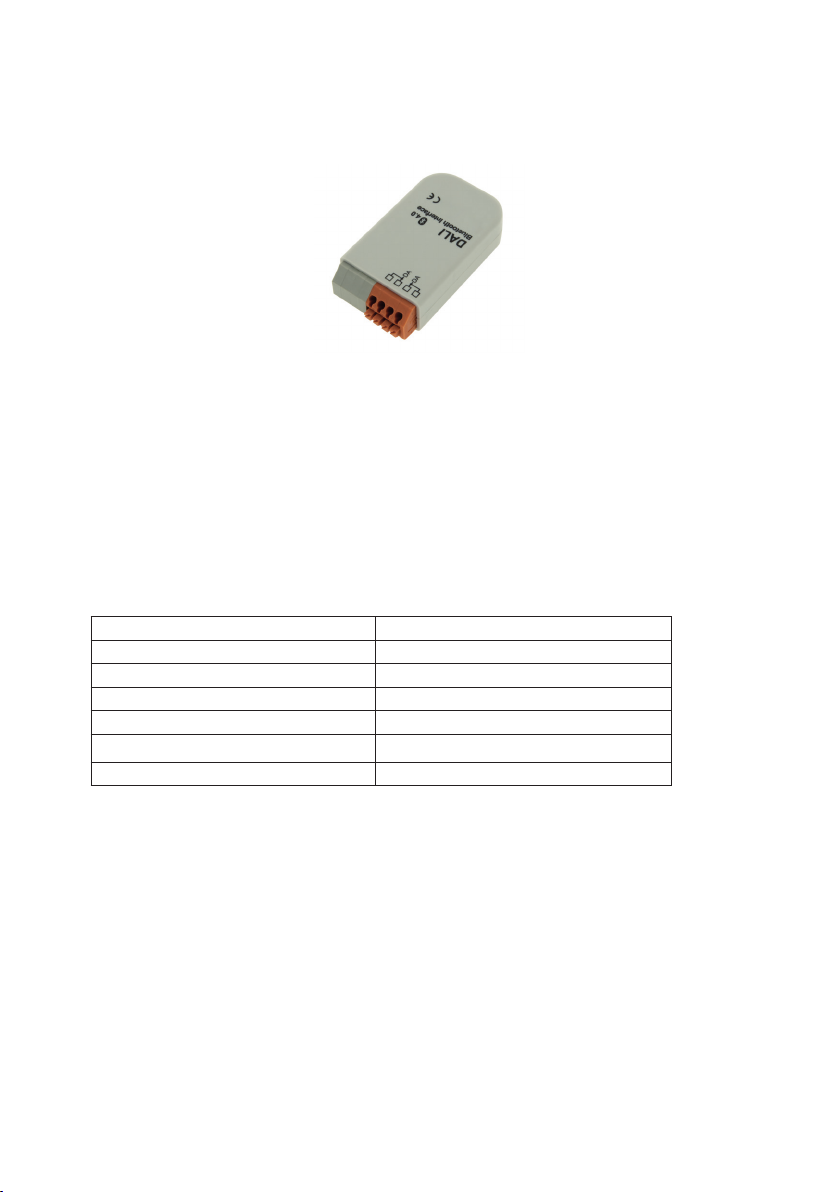
LED DALI Bluethooth Interface - User Manual
Item no: LC-004-304
1. Product Descripton
The DALI Bluetooth module are an interface device between IOS or Android Bluetooth
Low Energy capable mobile devices and DALI lighting systems. Apps are available for the menti-
oned operating systems.The function behind the layouts can be configured using the DALI-Cock-
pit software tool. It is supplied directly by the DALIline.
3. Description
2. Specification
1. Control of DALI systems via mobile devices (Android or iOS mobiel devices)
2. all Bluetooth modules are displayed in the reception are in the app
3. configurable up to 32 layouts
4. 5 predefined standard designs such as for switching and dimming, as well as for the control of
color and color temperature
5. Access code by pin-code us possible
6. Configuration of DALI Bluetooth module via DALI Cockpit and DALI USB Interface
7. freely positionable keys can be assigned functions
8. Ability to send DALI commands or command sequences to individual addresses (1-64), groups
(1-16) , and broadcast
9. Muli master operation, several modules can be installed per DALI circuit
10. The supply of the module is carried out directly via the DALI Line
Power Supply via DALI-Bus
typ. current consumption 4mA
Layout selectable
Output DALI
max. wire cross section 1,5 mm2
Dimensions (L x W x H) in mm 59 x 33 x 15 mm
weight 13g

4. Dimensions
5. User Manual
5.1. Function
The DALI Bluetooth module are an interface device between IOS or Android Bluetooth
Low Energy capable mobile devices and DALI lighting systems. Apps are available for the menti-
oned operating systems.
With the help of the App the DALI-system can be controlled using several layouts, but there can
be connected only one mobile device at the same time.
The function behind the layouts can be configured using the DALI-Cockpit software tool. For a
module up to 32 layouts and a maximum of 12 buttons per layout are supported (firmware 4.0
and higher). Furthermore 5 standard designs are availabe. They can be used either as
predefined or customized.
5.2. DALI-Touch App
The „DALI Touch“-App is available for IOS and android and can be downloaded from:
AppStore: https://itunes.apple.com/us/app/dalitouch/id994496429?ls=1&mt=8
Google Play: https://play.google.com/store/apps/details?id=com.lunatone.dalitouch
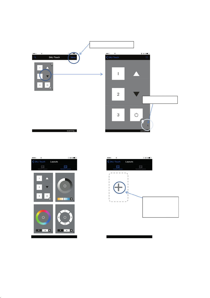
After app installation has been finished and the Bluetooth-module has been connected to
the DALI line (see chapter 4 - installation), the app is already connected to the module. In the
“app-overview” all Bluetooth modules located within the range are shown with their currently
“active layout” (see figure 1).
If one of the modules is selected in the “app-overview”, the layout comes up (figure 2) and the
DALI circuit can already be controlled by the functions defined in the layout.
On the right bottom of the layout the layout number is shown. If any changes on the function are
required, then this number indicates the layout which has to be adapted in the DALI-Cockpit.
The pics used for the different layouts are managed in the “layout-library”. It can be accessed
via the ”Manage Layouts“ in the main menu (“app overview”). In “Standard-Layouts“ (figure 3)
the predefined layouts (number 1-5) are listed whereas in the „Customized-Layouts“ (figure 4)
for each number from 100-255 (range for customized layouts) a pic from the memory of your
mobile device can be assigned. Already assigned pics can at any time be removed, changed or
assigned to another layout by changing the number (figure 5 and figure 6).
Finally the used pics can be sent per email e.g. for using exactly the same pic in the
DALI-Cockpit config tool when configuring the corresponding layout.
Menu - > Manage Layouts
layout number
1: „app-overview“ located modules 2: „active layout“
Manage Layouts:
add a pic as
customized layout
3: „layout-library“ - standard 4: „layout-library“ - customized

5: Customized Layout 100 6: Edit option
additional hints:
7: searching for connection 8: coordinates of lasst pressing action
Layout 100 added:
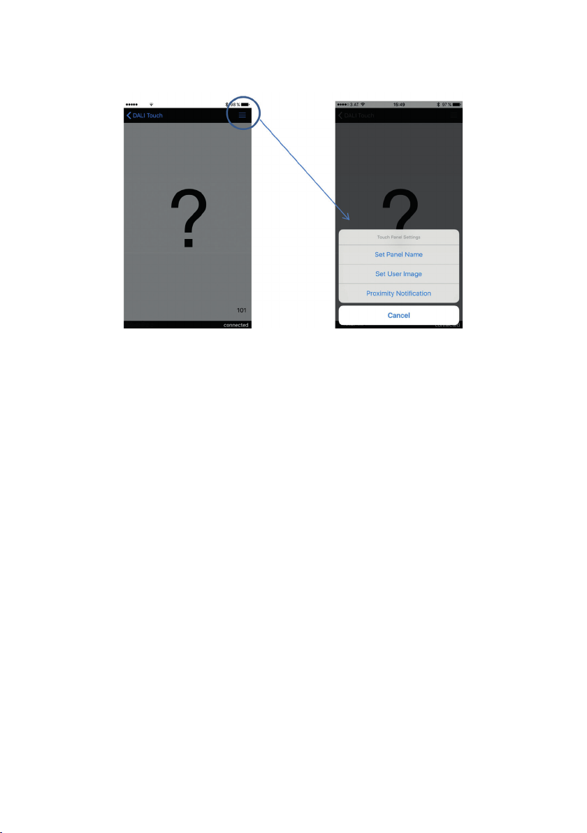
9: unknown layout (no pic assigned) 10: layout menu
The search for a bluetooth connection is indicated by the symbol shown in figure 7.
After a pressing action the coordinates at which the action has been located is shown (in% rela-
tive to the screen size) for about 3 seconds on the bottom right (see figure 8). This information is
quiet helpful for the definition of button coordinates in the DALI-Cockpit.
If the case occurs that a layout gets active, for which no pic has been assigned (like it is the case
with layout 101 in figure 9), a big question mark will indicate this behaviour. The pic can then be
assigned to Layout 101 either via “Manage Layouts” as already mentioned above or using menu
function ”Set User Image“ (see layout menu figure 10).
The difference between these methods is as follows: The app has one “layout-library” in use,
that means that each Bluetooth module that connects to the app uses the same layout-library
and as a result the same pics for the same layout numbers. In difference a “User image” is
only assigned to the currently active layout of the connected device, the pic defined in the layout
manager is overruled in this case.
Besides the definition of a user image the panel name can be set as well as the proximitiy notfi-
cation can be enabled/disabled in the layout menu (see figure 10).

5.3. DALI-Cockpit - Layout Configuration
The DALI Cockpit is the configuration tool for DALI systems and it is available as free
download. Please check that you have the last recent version in use, otherwise it cannot ensure
that all functions and devices are supported (for DALI BT-modules please use DALI-Cockpit
Version 1.25 and higher).
With the help of the DALI-Cockpit DALI control gear and control devices can be addressed and
configured. All devices that are connected to the DALI-line and have been addressed are listed in
the component tree (figure 11).
11: Component-Tree
DALI Touch BT module
DALI Bluetooth module
Selecting a device in the component tree will open the corresponding configuration site.
5.3.1. General Settings
The configuration site of the DALI Bluetooth modules is separated in tabs, one for each layout
and a general settings tab.
On the left there general functions like the info-field about the number of layouts and the but-
tons for adding/removing layouts and assigning/removing pics to layouts are located. The touch-
panel-type offers an additional button for calibration of the physical touchpanel (see figure 12).
The header, marked as device info, provides information about the device (like manufacturer,
article number, serial number and firmware version).
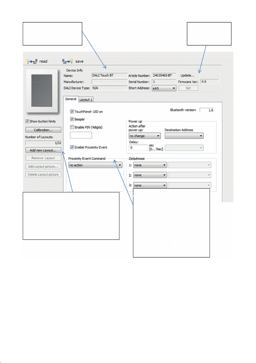
device info:
type, manufacturer, etc.
firmware version
update function
Add Layout:
Standard layout
Empty layout
Copy of already existing layouts
General Settings:
pincode (access protection)
proximity event
power-up behaviour
touchpanel LED
General Settings:
Enable PIN: access protection by a 4 digit pin code. Once activated the app of a connected mobile
device will ask for a valid pin.
proximity event: the proximity function offers the possibility to set a predefined action if a mobile
device comes into the range of the bluetooth connection (e.g. for automatic switch on the light).
The proximity function has to be enabled on the mobile device as well (function is supported up
from Bluetooth version 1.0 and firmware version 4.3).
power-up: behaviour after a power brake has occured
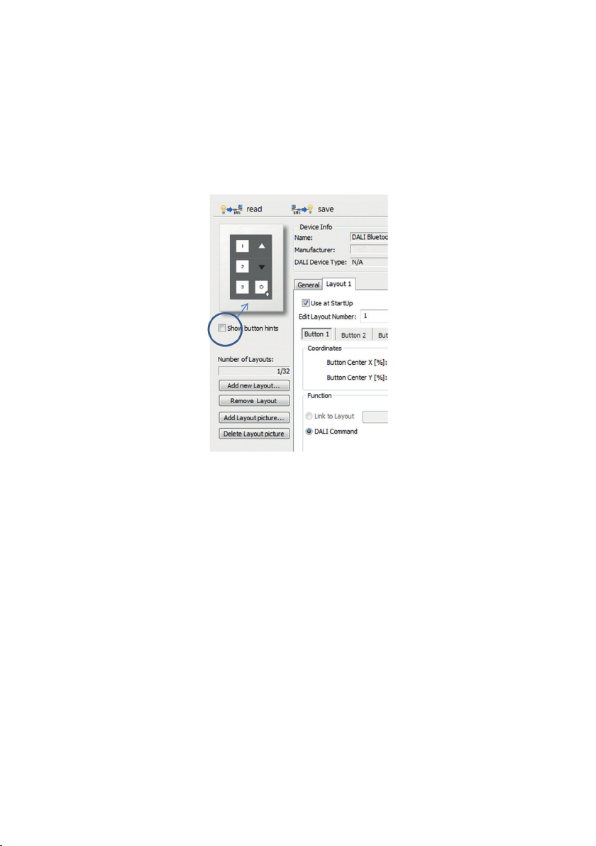
5.3.2. Layout Settings
Once a layout is selected addional options are available in the menu on the left. The selected
layout can be deleted and the image that should be used for the layout can be selected. This
is useful for defining the coordinates of the buttons. The buttons defined in the layout can be
superimposed or supressed dependent on the „Show button hints“ checkbox.
13: DALI Bluetooth Module
Hint: A Start-Layout (DALI Bluetooth, „Use at StartUp“) must be available at any time.
This layout cannot be deleted. If the currently active layout has been deleted accidentally, a pow-
er cycle restarts the module in a defined state using the startup-layout as active layout.
Layout Number:
The number of the layout can be changed in the field „Edit Layout Number“ (100…255), the num-
ber is used by the module to tell the app which layout (pic) should be shown.
Furthermore the layout numbers are used for the link-function. Assigning a link to another
layout to a button offers the possibility to switch between several layouts and generate menu
structures and so on.
Buttons:
Each layout supports up to 12 buttons. The position of each button is defined by its coordinates,
in detail by its centre as well as its width and height. The coordinates are entered in % relative to
the layout size (0/0 is top left, 100/100 is bottom right – see figure 8 and figure 15).
The coordinates shown in the app when touching the layout are very helpful for defining the
centre of a button.
If the checkbox „Show button hints“ is selected, the areas of the defined buttons will be
superimposed to the background pic. The currently active button is highlighted.
Button areas may overlap, in this case the button with the higher number has higher priority
(like in fig 15 at which button 7 has higher priority than button 6).
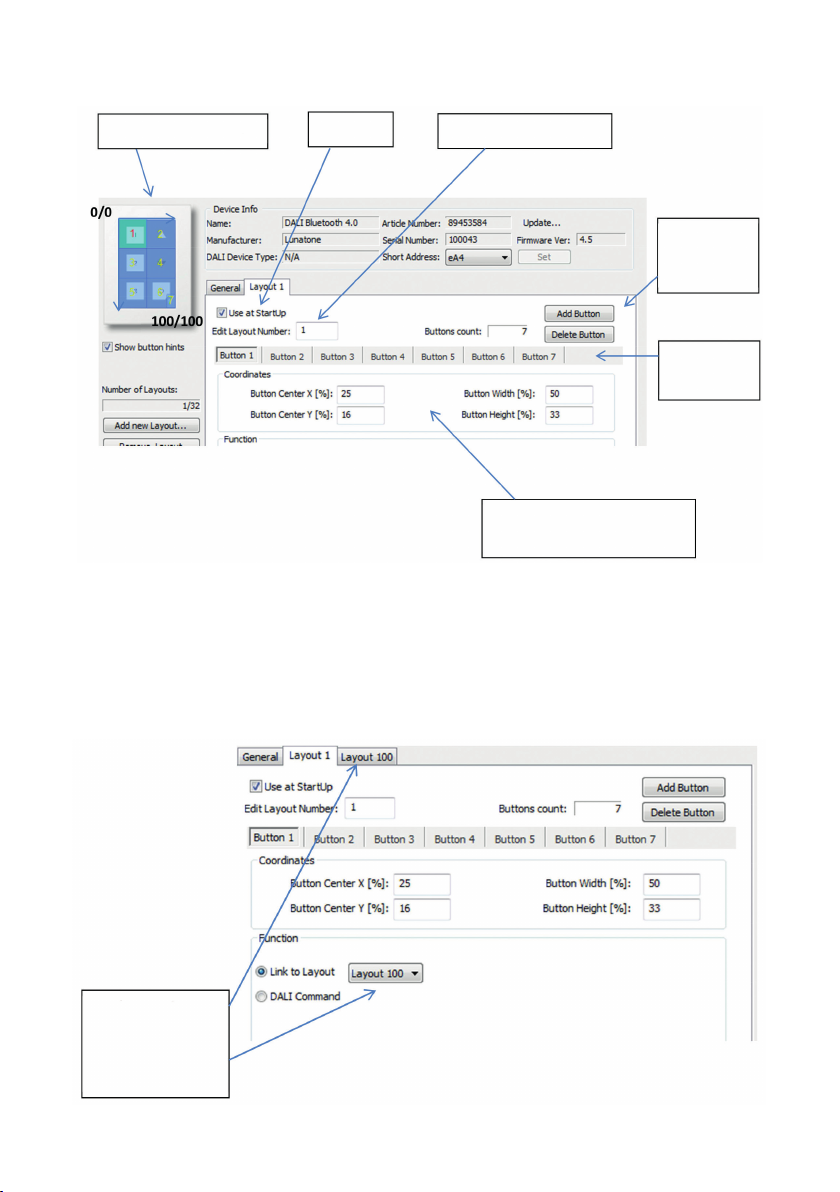
Visualisation of Buttons Power Up Layout Number (App)
Button Coordinates (Centre,
Width, Height)
Add /
Remove
Button
Tabs for
Buttons
15: Layout Page Settings
Function:
Each button a function can be assigned to. As function 2 different types are available:
· a link to another layout, this allows switching between different layouts and thus offers the
generation of structures with submenus and so on
Function: Link
selectable only if
other layouts are
available
16: Link-Function

· a DALI command, this option includes several possibilities to send DALI commands on the
DALI-line
Detailed DALI Settings:
Effective range
Switching function
DALI command
DALI-Function:
Adress(es) +
Commands
17: DALI-Function
5.4. Installation
The DALI-Bluetooth module is connected directly to the DALI-line. It is supplied directly by the
DALI line. The connection to the DALI-line is polarity-free.
The DALI Touch BT can be mounted on a wallbox, the DALI Bluetooth module can be inserted
inside. Connecting wire cross section is 1,5mm2 (Interface only type).
The DALI-Bluetooth modules are mutlimaster capable, that means that several modules can be
connected to the same DALI-line.
The DALI-Bluetooth module does not use a DALI address, hence all 64 addresses can be used
for control gear..
5.5. Firmwareupdate
Please ensure that you are using the last recent DALI-Cockpit version.
Update Procedure:
1. Connect the DALI-Bluetooth Modul to the DALI-line. Connect your computer with the DALI-
Cockpit to the DALI-line using a DALI-USB or DALI RS232 interface.
2. Open the DALI-Cockpit and address the devices. Select the device in the component tree

The site will look similar to the example: (old firmware version 3.6)
Update
Button
Firmware
Version
18: DALI Cockpit view with DALI Bluetooth Firmware 3.6
3. Press the update button and enter the code from the Zip-File for enabling the update feature
4. The update window pops up -> Select the hex-file from the Zip and press start. The update
can last up to 15 minutes.
19: Firmware Update
5. After the Update has finished, the device must be readdressed (right click on the device in
the component-tree and selecting “delete” removes the device from the component-tree
and deletes the address).
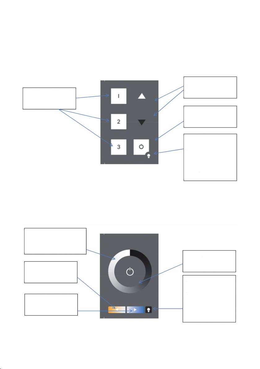
6. Appendix A: Standard-Layouts
The well known layouts used by the DALI-Touchpanel can be loaded as presets and modified by
the customer. Standard Layouts:
Finder-LED:
Red LED to find the physical
touch in the dark
Long Press:
LED On/Off
Scene Buttons:
Recall Scene 1-3
Dim Buttons
Dim Up and Dim Down
ON/OFF:
On/Off Button
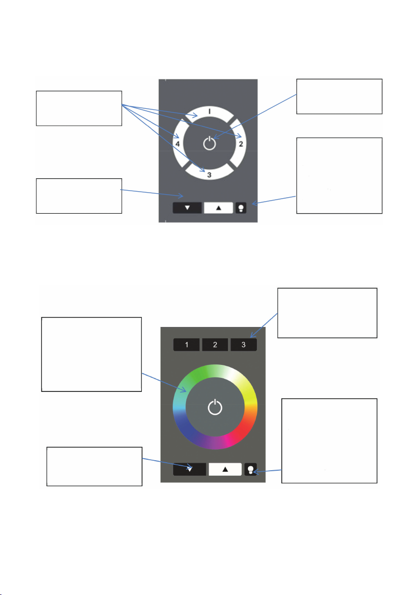
6-Button Layout (Standard Layout No. 1)
Finder-LED:
Red LED to find the
physical touch in the
dark.
Long press: LED On/Off
Dim Wheel:
Recalls discrete DAP-Values
Color Temperature:
Warmer
Color Temperature:
Cooler
Tunable White Layout (Standard Layout No. 2)
On(Off:
On/Off dependent on
the light status
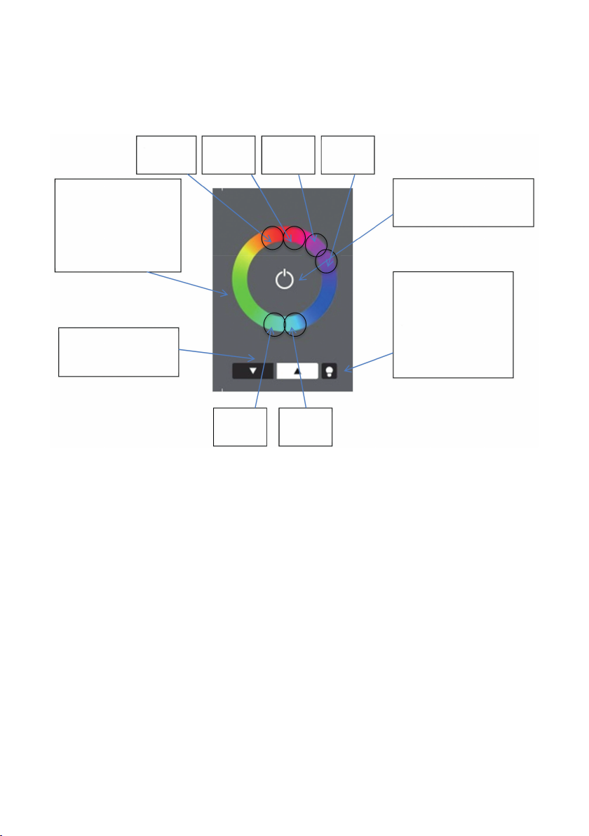
Color Layout (Standard Layout No. 3)
The Color Wheel is divided in 16 scenes. When you touch the wheel a GOTO SCENE X command
is sent to the effective range. The scene number depends on the position.
Finder-LED:
Red Led to find the physical
touch in the dark.
Long Press:
LED On/Off
Color Wheel:
Selecting a Color, the
corresponding GOTO
SCENE Cmd is sent.
Dim Buttons
Dim Up and Dim Down
On/Off:
On/OFF dependent on
the light status
Goto
Scene 15
Goto
Scene 8
Goto
Scene 7
Goto
Scene 0
Goto
Scene 1
Goto
Scene 2
The device does only recall scenes when using this layout. The color values have to be stored in
the scenes of the control gear itself. The big advantage of this method is that it can be used for
DT8 capable control gear as well as for systems using one address for each color.
Finder-LED:
Red LED to find the
physical touch in the
dark.
Long Press: LED On/Off
Scene Buttons:
Recall Scene 1-3
Dim Buttons
Dim Up and Dim Down
On/Off:
On/Off dependent on
the light status
7-Button Layout (Standard Layout No. 4)
Finder-LED:
Red Led to find the
physical touch in the
dark.
Long press: Led On/Off
Color Wheel:
Selecting a Color, the
corresponding GOTO
SCENE Cmd is sent.
Dim Buttons
Dim Up and Dim Down
Color Layout with Address-Selection (Standard Layout No. 5)
Address Select Button
Select effectie Range

DA
DA
DALI
AKTOR
DA
DA
DALI
AKTOR
DA
DA
DALI
AKTOR
DA
DA
DALI
AKTOR
Max. 64 DALI Aktoren
Max. 64 DALI Actuators
L
N
230V~
POWER
PE
DALI PS2 Bus Stromversorgung
Leuchteneinbau | Bus Power Supply
Fitting In Luminaires
LC-004-150
DA
POWER
IN
230V~
DA
L
N
DALI
OUTPUT
max.
220mA
ca.16V=
DALI Bluetooth Interface
LC-004-304
DALI
DA
DA
5. Wiring Diagram
Connection
The DALI Bluetooth has to be connected directly to the DALI bus. It is supplied with power by
the DALI bus and does not need any additional power supply. A typical value of the current
consumption is approximately 4mA. In order to supply additional components on a DALI line the
installation of a power supply (DALI PS) is required. The connection to the DALI-line is polarity
free and immune to overvoltage. The module fits into a standard lush mount box.
Table of contents
Other AUTLED Recording Equipment manuals


Popular Recording Equipment manuals by other brands


Lexicon
Lexicon 300L - owner's manual
 Output... user guide")
Altinex
Altinex Wall Mount Interface with Twisted Pair (TP) Output... user guide

Phonocar
Phonocar 5/845 Manual instructions

Roland
Roland TD-6 quick start guide

Homematic IP
Homematic IP HmIP-FWI Installation and operating manual

Bosch
Bosch HPC 410 Installation instructions for contractors