SeaSTAR Pro Series Quick start guide

SeaStar Sport Tilt Helms
INSTALLATION INSTRUCTIONS
AND OWNERS MANUAL
Before you do it your way,
please try it our way
www.seastarsteering.com
ISO 9001
MANUFACTURED BY
TELEFLEX CANADA LIMITED
PARTNERSHIP

SEASTAR
Don't compromise performance... use genuine
SeaStar parts only!
• SeaStar helms • SeaStar Cylinders
• SeaStar hoses • SeaStar Oil
Substituting non SeaStar parts in any part of the SeaStar hydraulic
steering system, may seriously compromise system performance.
Throughout this publication, Warnings and Cautions (accompanied by
the International Hazard Symbol ) are used to alert the manufacturer
or installer to special instructions concerning a particular service or
operation that may be hazardous if performed incorrectly or carelessly.
Observe Them Carefully!
These “safety alerts” alone, cannot eliminate the hazards that they
signal. Strict compliance to these special instructions when performing the
installation and maintenance plus “common sense” operation are major
accident prevention measures.
Notice to Boat Manufacturer
or Installer
Hazards or unsafe
practices which
COULD result in
minor injury or
product or property
damage.
Hazards or unsafe
practices which
COULD result in
severe personal
injury or death.
CAUTION
NOTICE
WARNING
Information which
is important to
proper installation or
maintenance, but is
not hazard-related.
Immediate hazards
which WILL result
in severe personal
injury or death.
DANGER
Cleaning fluids containing ammonia, acids or any other corrosive
ingredients MUST NOT be used for cleaning any part of this
Hydraulic Steering System. Failure to comply will cause serious
damage to the steering system, resulting in possible loss of
steering, causing property damage, personal injury and/or death.
WARNING

Sport Tilt Helms i
SAFETY INFORMATION
The safe operation of the steering system is dependant upon proper
installation and maintenance, common sense, safe judgment and
the knowledge/expertise of the operator. Every installer/user of the
steering system should know the following requirements 'before'
installing/using the steering system.
If you have any questions regarding any of these warnings, contact
Teleflex Marine.
To reduce risk of severe injury or death. Always wear a Coast Guard
Approved personal flotation device (PFD) and use an engine shut-off
cord (lanyard).
1. Read and understand the Installation and Owner’s Manuals
provided with your steering components.
2. Ensure that all components required to complete the installation
are on hand (including hoses, fittings, oil and the proper tools
required for the installation).
3. SeaStar components are highly engineered and safety tested to
ensure system integrity, DO NOT substitute any component with
non-SeaStar components as this may compromise system
performance/reliability.
1.
Install components as directed in all Installation Manuals (including
helm pumps, hoses and fitting kits).
2. DO NOT modify or substitute any component in any way without
written consent from Teleflex Marine.
3. Comply with all system ratings/regulations (boat/engine, U.S.C.G.).
- Cylinder MUST be compatible with engine(s)/rudder(s) and/or
outdrive(s) installed.
-
Cylinder MUST be rated for use on the engine(s) installed (outboard
applications).
4.
Confirm that there is no interference between the steering cylinder(s),
tiebars and the transom, splashwell, outboard engine or jackplate or
any combination of these parts by performing the following steps;
a)
With engine fully tilted DOWN, turn steering wheel from hard over
to hard over and confirm that no interference occurs.
-
if using a hydraulic jack plate the above must also be performed
at all the positions of the jack plate
.
b) Repeat step 4a) with engines tilted UP.
c) Perform step 4a) with each engine in DOWN/UP positions
confirming that independent TRIM/TILT can be done without
any interference.
5. Confirm that the steering cylinder can be fully stroked in both
directions as well as full tilt and trim without stretching, chafing,
rubbing and/or kinking of the hydraulic hoses.
6. Confirm that extruded nylon tubing has NOT been substituted
for SeaStar Steering Hose. Outboard applications only.
7. DO NOT use a wire coil type trim switch with a hydraulic steering
system as the wire can wind up tight around the steering wheel
shaft and prevent further steering.
8. Conduct Oil Level and System Check as outlined in your steering
cylinder manual.
Before installation
Installation
The safety information provided below is intended to inform you of the
dangers that may be present before, during and after the installation.
It is critical that you read and understand ALL the points noted.
WARNING

ii SEASTAR
TILT HELM INSTALLATION
SEASTAR ProSeries
During use
After use
Maintenance
Prior to every use 1. Check Fluid level in highest helm pump (refer to your steering
cylinder manual for proper fluid level setting).
2.
Verify immediate steering response when turning steering wheel(s).
(Ensure engine turns when steering wheel is turned.)
3. Visually inspect all steering hoses and fittings for wear, kinking
and/or leaks.
4. Check for binding, loose, worn or leaking steering components.
DO NOT OPERATE BOAT IF ANY COMPONENT IS NOT IN PROPER
WORKING CONDITION.
1. WEAR A COAST GUARD-APPROVED PERSONAL FLOTATION
DEVICE (PFD).
2. ATTACH ENGINE SHUT-OFF CORD (LANYARD) TO YOUR PDF.
3. Never allow anyone not familiar with the operation of the
steering system operate the boat at any time.
4. Know and adhere to the operator restrictions for your area
including;
- Federal Laws/Regulations,
- State Laws/Regulations and
- Municipal Laws/Regulations.
DO NOT OPERATE BOAT IF ANY COMPONENT IS NOT IN PROPER
WORKING CONDITION.
1.
Rinse off steering system thoroughly using 'fresh, clean water only'.
- Cleaning fluids containing ammonia, acids or any other corrosive
ingredients MUST NOT be used for cleaning any part of the
hydraulic steering system.
1.
Maintain steering system at a minimum of twice per year.
- See Maintenance section
in your steering cylinder manual
.
Keep our waters clean for all current and future users. Dispose of
ALL fluids in accordance with your local regulations.
Safety Information Continued
The safety information provided below is intended to inform you of the
dangers that may be present before, during and after use. It is critical
that you read and understand ALL the points noted.
WARNING

Sport Tilt Helms 1
The SeaStar Steering System is the smoothest and most efficient
hydraulic steering system available today. They have been designed
for normal pleasure and commercial use where standard rigging
arrangements are used. Before proceeding with the installation of
this tilt helm, read these instructions thoroughly. Teleflex Marine
cannot accept responsibility for installation where instructions have
not been followed, where substitute parts have been used, or where
modifications have been made to our products.
This Installation and Owner's Manual covers ALL SeaStar, Sport and
Sport Plus Tilt helms. Any differences between the helms will be
noted where required.
Due to a small amount of internal oil slip, a “master spoke” or
“centered” steering wheel (such as those used in automobiles) will
not maintain a straight ahead wheel setting. For best results, use
an “equal distance spoke” steering wheel.
NOTICE
Help protect your boating environment by ensuring that all used oil
is disposed of properly.
INTRODUCTION
Index
Safety Information ...................................................................... i
Introduction .............................................................................. 1
System Installation Overview ..................................................... 2
Tilt Helm Template .................................................................... 3
Sport Tilt Helm Mounting .......................................................... 5
Sport Tilt Helm Installation ....................................................... 6
Sport Plus Tilt Helm Mounting .................................................. 7
Sport Plus Tilt Helm Installation ................................................ 8
Remote Fill & Vent Kit Installation ............................................. 9
Troubleshooting Guide ............................................................. 10
Warranty policy/procedures .................................................... 11
To assist in future troubleshooting, note your helm pump part
number here:
HH_____________________.
NOTICE

2SEASTAR
REMOTE FILL AND VENT KIT INSTALLATION:
Using page 8 In this manual, install the helm fill and vent kit
FILLING AND PURGING OF STEERING SYSTEM:
Using the Fill and Purge instructions provided in your steering cylinder
manual, fill and purge the steering system.
OIL LEVEL AND SYSTEM CHECK:
Using the “Oil level and system checks” provided in your steering
cylinder manual, confirm proper operation of your steering system.
TILT HELM INSTALLATION:
Install your Tilt Helm as per the detailed installation instructions on
pages 6–7 of this manual,
STEERING CYLINDER INSTALLATION:
Install your steering cylinder as per the Installation manual provided
with your cylinder.
Step 3
SYSTEM INSTALLATION
OVERVIEW
Step 1
Step 4
Step 2
Step 5
CYLINDER

Sport Tilt Helms 3
TILT HELM INSTALLATION
SEASTAR ProSeries
Tilt Helm Mounting Template
✁
E L O H 1
) m m 7 7 ( . A I D " 3
) m m 5 . 2 8 ( " 4 / 1 - 3
) m m 5 . 1 2 ( " 5 8 . 0
1-27/32" (47mm)
S E L O H 3
) m m 8 ( . A I D " 6 1 / 5
2-3/8" (60mm)
29/32" (23mm)
2.57" (65mm)
E N I L T U O E G N A L F M L E H
) m m 5 . 0 2 1 ( " 4 / 3 - 4
) y l n o e c n e r e f e r r o f (
If you must photocopy this mounting
template for use, check ALL
measurements using a measuring device
prior to using as a template.
NOTICE
TILT HELM TEMPLATE

4SEASTAR

Sport Tilt Helms 5
TILT HELM INSTALLATION
SEASTAR ProSeries
SPORT TILT HELM
MOUNTING
13
15
6
10
DASHBOARD
1HELM PUMP
14
LIP #1
LIP #1
LIP #2
LIP #2
THREAD LOCK
PRE-APPLIED
BY FACTORY
11
12
9
2
3
5
4
7
8
Figure 1
WARNING Use the self-locking fasteners provided ONLY; substituting non-self
locking fasteners can result in loosening or separation of equipment
leading to loss of steering control causing property damage and/
or personal injury.
ITEM PART # QTY DESCRIPTION
1 279068 1 Tilt Plate
2 954829 3 CB 1/4" NC x 2"
3 201429 3 Washer, 1/4" Flat SS
4 067424 3 Nut, 1/4" NC, Nyloc®
5 007279 4 HHCS 1/4" NC x 2-1/2" SS
6 279021 1 Tilt Mechanism
7 757927 1 SCHS #10-24 x 7/8" SS
8 958627 2 PHMS 5/16" NC x 3/4"
ITEM PART # QTY DESCRIPTION
9 957725 2 Washer, Star
10 157616 1 Boot Latch
11 157477 1 Bezel, Lower
12 952623 2 #8-32 x 1"
13 157512 1 Below
14 260130 1 Shaft Key
15 747521 1 Wheel Shaft Nut

6SEASTAR
TILT HELM INSTALLATION
SEASTAR ProSeries
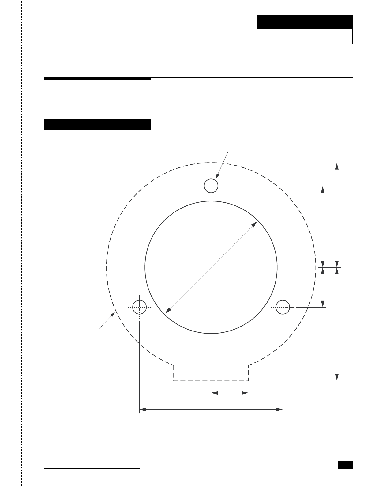
STEP 1. Using the template provide on page 3. Confirm that the
location of the Tilt Helm will allow unrestricted operation of the
steering wheel in ALL tilting positions and will NOT interfere with
other functional equipment.
STEP 2. Tape the template to the dash and use a center punch for
locating the holes on the dash. Double check to ensure unrestricted
operation of the steering wheel in ALL tilting positions.
STEP 3. Drill the required diameter center hole and the specified
number and size of mounting bolts as shown in the template.
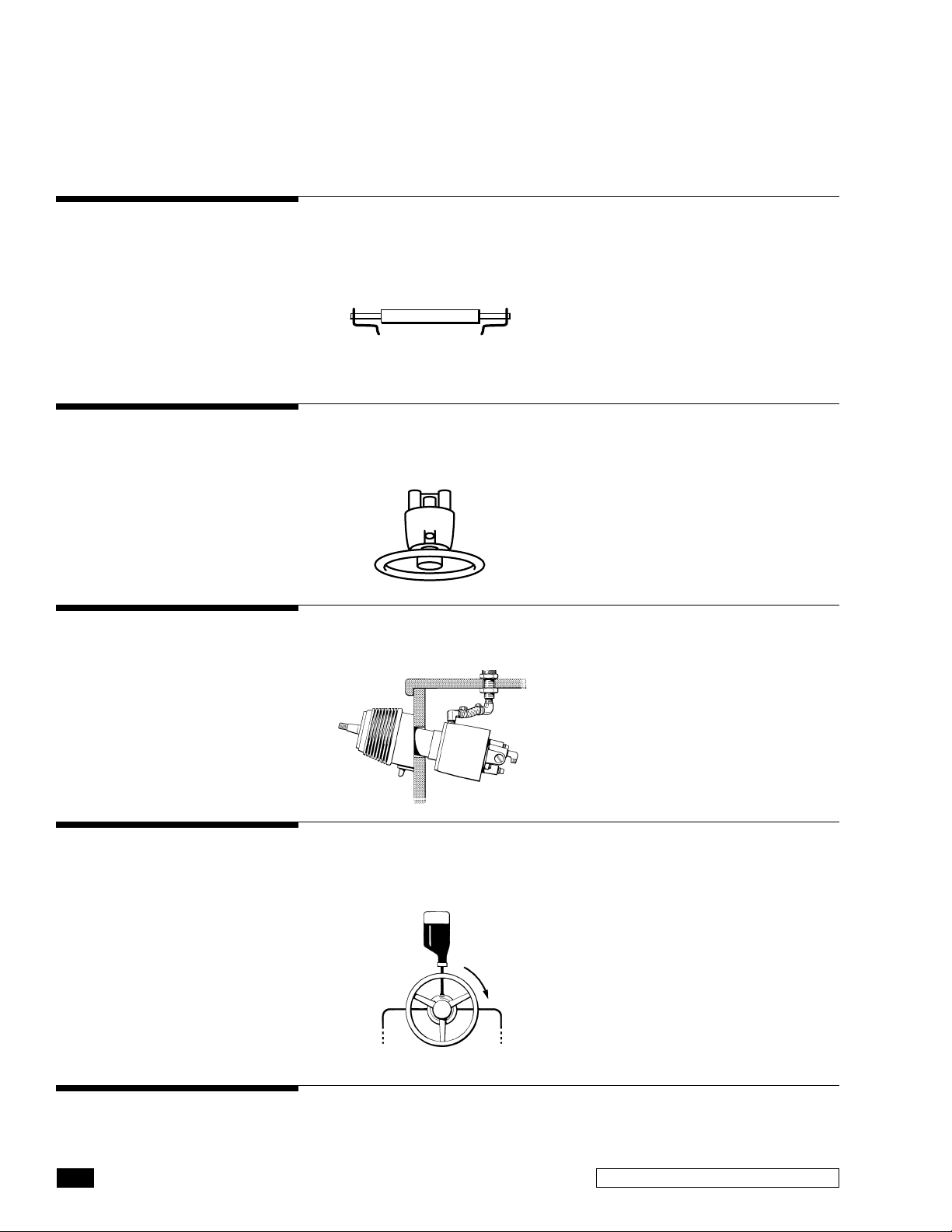
STEP 4.
Mount Tilt Plate (Item 1) to the dash using the three 1/4" NC x 2"
carriage bolts (Item 2), washers (Item 3) and self locking nuts (Item 4)
STEP 5.
Prior to mounting helm pump to the dash plate, install desired
fittings into the rear of the helm pump using Teflon based pipe sealant.
DO NOT use Teflon Tape, ONLY use paste style Teflon based pipe sealant.
STEP 6.
Mount the helm pump from behind the dash to the tilt
mounting plate (Item 1) so that the four helm mounting holes align with
the applicable holes in the tilt mounting plate. Apply a small mount of
the supplied Loctite® on ALL four of the 1/4 x 2-1/2" hex head bolts
(Item 5) and secure them to the helm pump.
STEP 7.
Attach the helm shaft to the tilt mechanism (Item 6) by
lining up the coupling slot with the helm shaft tongue and secure
with the no. 10 - 24 x 7/8" (Item 7).
STEP 8.
Tighten the two PHMS 5/16" NC x 3/4" screws (Item 8), and
star washers (Item 9) to secure the tilt mechanism to the dash plate.
STEP 9.
Install boot latch (Item 10) onto the tilt latch of tilt mechanism.
STEP 10.
Position the tilt unit in the middle position and mount the
lower bezel (Item 11) to the tilt mechanism ensuring that the boot latch
(Item 10) is held into the slots provided in the lower bezel (Item 11).
Secure the bezel with the two PHMS #8-32 x 1" (Item 12).
STEP 11.
Install boot cover (Item 13) over lip 1 of the tilt mechanism
and around lip 2 of the lower bezel. (shown in Figure 1).
STEP 12.
Grease steering shaft with a good quality marine grease.
STEP 13.
Install woodruff key (Item 14) and wheel shaft nut (Item 15).
Tighten wheel shaft nut prior to continuing on with instructions.
Torque wheel shaft nut to 150 in/lb, DO NOT exceed 200 in.lb.
STEP 14.
Confirm proper function of the tilt mechanism:
• Push the tilt latch forward to unlock the tilt mechanism
•
Check ALL positions of the tilt and confirm that the latch locks in place
for each position, tilt lever will click back into the locked p
osition.
STEP 15.
ONLY if the tilting function is confirmed to function, continue
to page 8 for remote fill kit installation.
Sport Tilt Helm Installation
WARNING
NOTICE
WARNING
Use self-locking fasteners
provided ONLY; substituting
non-self locking fasteners
can result in loosening or
separation of equipment leading
to loss of steering control
causing property damage
and/or personal injury. DO
NOT exceed 110 in.lb. (12Nm)
torque on helm nuts and bolts.
If the helm pump shaft is difficult
to locate into the tilt mechanism
coupling, loosen the TOP screw in
the coupling by NO MORE than 1⁄4
of a turn. Ensure that this screw
is fully tightened before installing
the bezel.

Sport Tilt Helms 7
TILT HELM INSTALLATION
SEASTAR ProSeries
WARNING
SPORT PLUS TILT HELM
MOUNTING
ITEM PART # QTY DESCRIPTION
1 279064 1 Tilt Plate
2 984829 3 CB 1/4" NC x 2”
3 201429 3 Washer 1/4" Flat SS
4 067424 3 Nut, 1/4" NC, Nyloc®
5 007279 4 HHCS 1/4" NC x 2-1/2” SS
6 182110 1 Tilt Mechanism
7 757927 1 SCHS #10-24 x 7/8" SS
8 958627 2 PHMS 5/16” NC x 3/4"
ITEM PART # QTY DESCRIPTION
9 957725 2 Washer, Star
10 279049 1 Latch Boot
11 279041 1 Upper Bezel
12 279045 1 Lower Bezel
13 279082 5 BHSCS 8-32 x 1/2" SS
14 260130 1 Shaft Key
15 747521 1 Wheel Shaft Nut
13
15
6
10
DASHBOARD
1
HELM PUMP
14
LIP #1
THREAD LOCK
PRE-APPLIED
BY FACTORY
11
12
9
2
3
5
4
7
8
Figure 2
Use the self-locking fasteners provided ONLY; substituting non-self
locking fasteners can result in loosening or separation of equipment
leading to loss of steering control causing property damage and/
or personal injury.

8SEASTAR
TILT HELM INSTALLATION
SEASTAR ProSeries
NOTICE
Ensure that tilt latch boot (Item
10) is properly fitted into the slots
provided in the lower bezel.
STEP 1 Using the template provided on page 3. Confirm that the
location of the helm will allow unrestricted operation of the steering
wheel in ALL tilting positions and will NOT interfere with any other
functional equipment.
STEP 2 Tape the template to the dash and use a center punch for
locating the holes on the dash. Double check to ensure unrestricted
operation of the steering wheel in ALL tilting positions.
STEP 3 Drill required diameter center hole and the specified number
and size of the mounting bolts as shown in the template.
STEP 4 Mount Tilt plate (Item 1) to the dash using the three 1 ⁄4" NC
x 2" carriage bolts (Item 2, washers (Item 3) and self locking nuts
(item 4). Torque to 110 in/lb.
STEP 5 Prior to mounting the helm pump to the dash plate, install
desired fittings into the rear of the helm pump using a Teflon Based
pipe sealant. DO NOT use Teflon tape, ONLY use a paste style
Teflon based pipe sealant.
STEP 6 Mount the helm pump from behind the dash to the tilt
mounting plate (Item 1) so that the four helm mounting holes align
with the applicable holes in the tilt mount plate. Install the four 1⁄4"
x 2-1/2" hex head bolts (Item 5) and secure them to the helm
pump. Torque to 110 in/lb.
STEP 7 Attach the helm shaft to the tilt mechanism (Item 6) by lining
up the coupling slot with the helm shaft tongue and secure with the
one 10–24 NC x 7/8" bolt (Item 7). Torque to 20–24 in/lb.
STEP 8 Install and tighten the two PHMS 5/16" NC x 3⁄4" screws
(Item 8) and the star washers (Item 9) to secure the tilt mechanism
to the dash plate. Torque to 160–180 in/lb.
STEP 9 Install the boot latch (Item 10) onto the tilt latch of the tilt
mechanism.
STEP 10 Fit the upper bezel (Item 11) into the lower bezel (Item 12)
and position two parts over the tilt mechanism. Install the 5 x BHSCS
8-32 x 1⁄2" SS (Item 13) screws into the position show.
STEP 11 Grease steering shaft with good quality marine grade grease.
STEP 12 Install the woodruff key (Item 14) and wheel shaft nut
(Item 15), Tighten steering wheel shaft nut prior to continuing with
installation instructions. Torque wheel shaft nut to 150 in/lb.
DO NOT exceed 200 in/lb.
STEP 13 Confirm proper function of the tilt mechanism using the
following points.
Push tilt latch forward to 'unlock' the tilt mechanism.
Check ALL positions of the tilt and confirm that the latch 'locks' in
place for each position, tilt lever will click back into the locked position.
STEP 14 ONLY if the tilting function is confirmed to function,
continue with the 'Remote Fill and Vent Installation' as shown in the
installation manual included with the helm pump.
NOTICE
If the helm pump shaft is difficult
to locate into the tilt mechanism
coupling, loosen the TOP screw
in the coupling by NO MORE
than 1/4 of a turn. Ensure that
this screw is fully tightened
before installing the bezels.
Sport Plus Tilt Helm Installation

Sport Tilt Helms 9
TILT HELM INSTALLATION
SEASTAR ProSeries
This kit will provide means to fill and vent the steering system
above the dash or consul. A 3/4" hole will need to be drilled into
the dash/consul ABOVE the helm pump, prior to drilling any holes,
confirm that you will not drill into any functioning equipment.
1. Locate desired location for placement of the helm fill plug onto of
the dash/consul. Look beneath the dash/consul to confirm that
there is sufficient space for the fill hose and fittings. Confirm that
there is no interference with any other equipment. Mark the location
and drill a 3/4" hole from above or below the dash/consul.
2. Apply a Teflon based pipe sealant to the threads of the elbow
fitting going into the helm pump, DO NOT use Teflon Tape, ONLY
use the paste type pipe sealant. Screw one of the elbow barb
fittings into the applicable helm filling port.
Remote Fill & Vent
3.
Attach the vinyl tubing to the elbow fitting that you just installed into
the helm pump and secure with a hose clamp. A small amount of
oil inside the vinyl tube will help slide it onto the elbow barb fitting.
4. Insert fill fitting from the top of the dash/consul and secure with
the jam nut.
A spacer may be required if mounting surface is less than 3/8"
thick, this spacer is provided in this kit
5. Apply Teflon based pipe sealant to the threads of the elbow fitting
that will be installed into the fill fitting. DO NOT use Teflon Tape;
ONLY use the paste type pipe sealant.
6. Vinyl hose MUST have a gradual rise from the helm fitting to the
fill fitting to allow air to rise. Cut vinyl tube to the required length
and secure to the fill fitting with a hose clamp.
ELBOW HOSE
BARB FITTING
FILL FITTING
VENT PLUG
HELM PUMP
Figure 3
Remote Fill & Vent Kit Installation
NOTICE
Sport Tilt Shown, Sport Plus similar.

10 SEASTAR
TILT HELM INSTALLATION
SEASTAR ProSeries
TROUBLESHOOTING GUIDE
FAULT CAUSE SOLUTION
1. Cannot get helm shaft
to go into U-Joint.
U-Joint bolt is too tight. Loosen the "Top" bolt no more than 1/4"
to allow the Helm shaft to be installed.
2. Tilt will not lock into
place.
Spring has come undone.
Or a broken Tilt tooth.
Re-attach spring. Replace Tilt mechanism.
3. Fluid is leaking from
where the elbow fitting
is installed into the Helm
pump fill port.
No pipe sealant installed
onto threads. Hose clamp
not tightened down.
Re-apply Teflon
®
based pipe sealant, NO
TEFLON
®
TAPE. Tighten hose clamp fully.
4. Wheel is really hard to
turn in both directions.
Tilt boot is rubbing on the
steering wheel hub.
Confirm that the rubber boot is installed over
both lips and is NOT rubbing on the wheel
hub.
5. Cannot remove
steering wheel.
Seized in place. No grease
applied to shaft before
wheel installation.
Using your knee under the wheel and your
hand on top, with the wheel shaft nut installed
one turn on shaft, lightly tap helm shaft to
release wheel.

Sport Tilt Helms 11
Statement of Limited Warranty
Return Goods Procedure
We warrant to the original retail purchaser that Teleflex Canada
Limited Partnership products have been manufactured free from
defects in materials and workmanship. This warranty is effective
for two years from date of purchase, excepting that where Teleflex
Canada Limited Partnership products are used commercially or in
any rental or income producing activity, then this warranty is limited
to one year from the date of purchase.
We will provide replacement product without charge, for any Teleflex
Canada Limited Partnership product meeting this warranty, which is
returned (freight prepaid) within the warranty period to the dealer
from whom such product were purchased, or to us at the appropriate
address. In such a case Teleflex Canada Limited Partnership
products found to be defective and covered by this warranty, will be
replaced at Teleflex’s option, and returned to the customer.
The above quoted statement is an extract from the complete
Teleflex Canada Limited Partnership products warranty statement.
A complete warranty policy is available in our Teleflex Canada
Limited Partnership products catalogue.
Prior to returning product to Teleflex Canada Limited Partnership
under warranty, please obtain a Return Goods Authorization number
(claim number).
Be sure to label the goods with:
a) the name and address of the sender, and
b) the return goods authorization number (claim number)
Please address the returned goods as follows:
From U.S.A.
RGA # ?
Teleflex Canada Limited Partnership
c/o UPS–Supply Chain Solutions Inc.
Door A37
1201 C Street NW
Auburn, WA, 98001
From Canada
RGA # ?
Teleflex Canada
3831 No.6 Road
Richmond, B.C.
Canada V6V 1P6

TELEFLEX CANADA
3831 NO.6 ROAD
RICHMOND, B.C.
CANADA V6V 1P6
FAX 604-270-7172
www.seastarsteering.com
© 2006 TELEFLEX CANADA LIMITED PARTNERSHIP
PRINTED IN CANADA
FORM NO. 279102 04/11 Rev. F
ISO 10592
Table of contents
Other SeaSTAR Boating Equipment manuals
Popular Boating Equipment manuals by other brands

Vetus
Vetus RimDrive RD125 Operation manual

Sea Ray
Sea Ray Sport Series Installation/Care

TOHMEI
TOHMEI ANTI ROLLING GYRO ARG375T Operation instructions

Vetus
Vetus BOW16024C Operation manual and installation instructions

SureShade
SureShade Power Bimini Installation and owner's manual

EZ Dock
EZ Dock EZ Port & Stow Owner's manual and installation instructions