AUTOFLAME MM80006 User manual
04.08.2020
Combustion Management Systems
AUTOFLAME
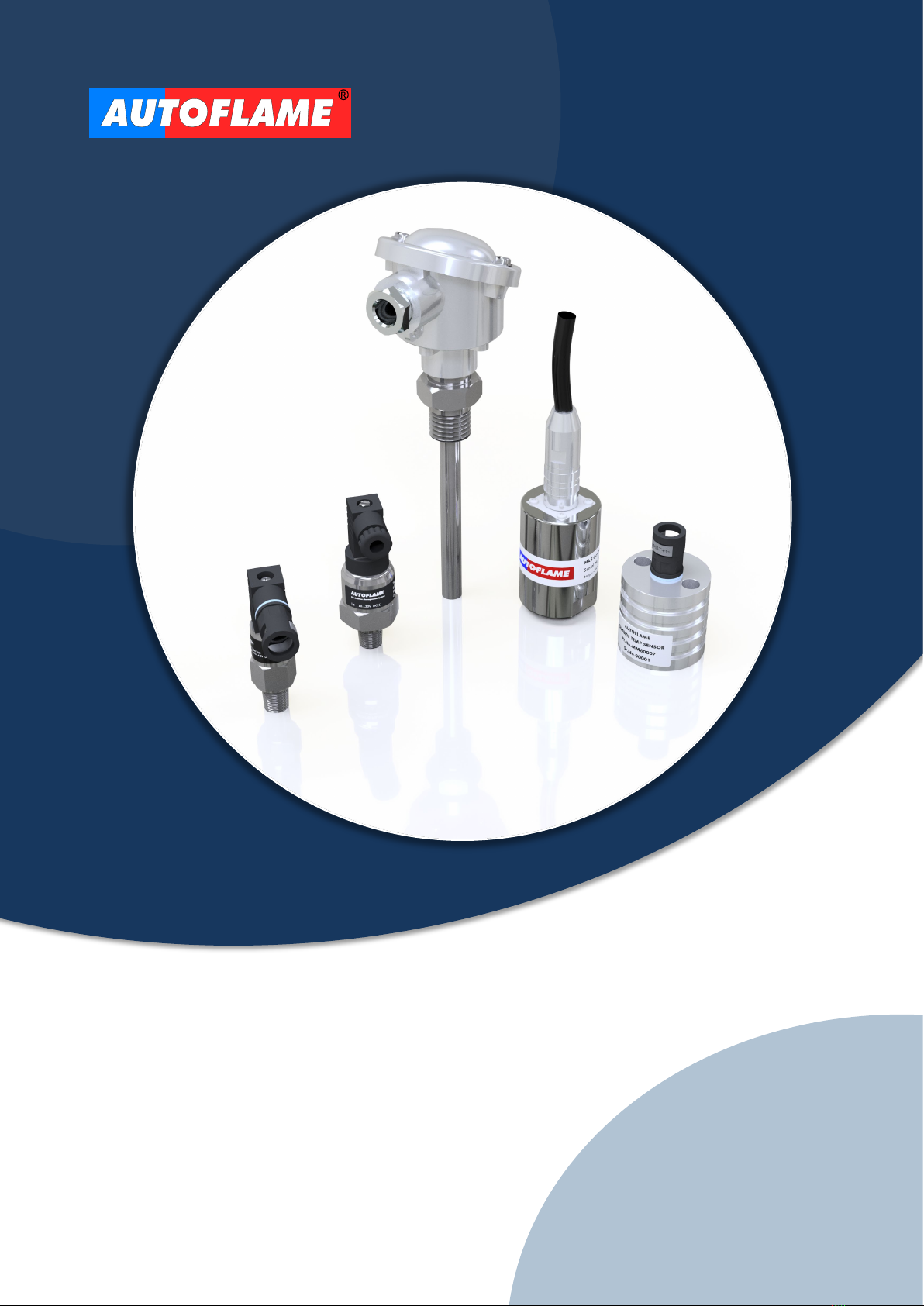
SENSORS GUIDE

Autoflame Engineering Ltd.
Unit 1-2 Concorde Business Centre
Airport Industrial Estate
Wireless Road, Biggin Hill
Kent TN16 3YN
United Kingdom
Combustion Management Systems
+44 (0)1959 578 820
Tel:
technicalsupport@autoflame.com
Email:
www.autoflame.com
Web:
AUTOFLAME
SENSORS GUIDE
04.08.2020
This manual and all the information contained herein is copyright of Autoflame Engineering Ltd. It may not be
copied in the whole or part without the consent of the Managing Director.
Autoflame Engineering Ltd’s policy is one of continuous improvement in both design and manufacture. We
therefore reserve the right to amend specifications and/or data without prior notice. All details contained in this
manual are correct at the time of going to print.

Important Notes
A knowledge of combustion related procedures and commissioning is essential before embarking work on any
of the MM/EGA systems. This is for safety reasons and effective use of the MM/EGA system. Hands on training
is required. For details on schedules and fees relating to group training courses and individual instruction,
please contact the Autoflame Engineering Ltd. offices at the address listed on the front.
Short Form - General Terms and Conditions
A full statement of our business terms and conditions are printed on the reverse of all invoices. A copy of these
can be issued upon application, if requested in writing.
The System equipment and control concepts referred to in this Manual MUST be installed, commissioned and
applied by personnel skilled in the various technical disciplines that are inherent to the Autoflame product
range, i.e. combustion, electrical and control.
The sale of Autoflame’s systems and equipment referred to in this Manual assume that the dealer, purchaser
and installer have the necessary skills at their disposal. i.e. A high degree of combustion engineering
experience, and a thorough understanding of the local electrical codes of practice concerning boilers, burners
and their ancillary systems and equipment.
Autoflame’s warranty from point of sale
•Two years on all electronic and electro-mechanical equipment, assemblies and components.
•One year on all EGA systems and UV & IR scanners, including parts, components, cells and sensors.
The warranty assumes that all equipment supplied will be used for the purpose that it was intended and in
strict compliance with our technical recommendations.
Autoflame’s warranty and guarantee is limited strictly to product build quality, and design. Excluded absolutely
are any claims arising from misapplication, incorrect installation and/or incorrect commissioning.

IMPORTANT SAFETY NOTES
Autoflame sensors must only be installed, wired, commissioned or
adjusted by an Autoflame trained and certified technician.
Any person installing, wiring, commissioning or adjusting the sensors
without undergoing proper Autoflame training and without full understanding of the Micro
Modulation (MM) system may put themselves and others in a seriously dangerous
situation that can result in serious injury or even death, and may cause permanent
equipment failure and substantial property damage.
Some of the wiring connections are live, make sure to totally and safely isolate the mains
power before undergoing any work related to the sensors. Failure to do so can result in
fatal injury.
It is the responsibility of the commissioning technician to ensure that all relevant Valve
Proving System (VPS) and air pressure proving standards are adhered to.
This guide must be read in conjunction with the relevant MM system manual.
!

Contents
1. AUTOFLAME SENSORS............................................................................................................... 6
2. GAS & AIR PRESSURE SENSORS (MK8 SERIES) .................................................................... 7
2.1. Installation........................................................................................................................................ 10
2.2. Mk8 MM Gas Pressure Sensor Applications................................................................................... 13
2.2.1. VPS / Pressure Limits with Vent Valve............................................................................. 13
2.2.2. VPS / Pressure Limits, No Vent Valve.............................................................................. 14
2.2.3. VPS / Pressure Limits with Vent Valve, Single Valve Pilot............................................... 14
2.2.4. VPS / Pressure Limits, No Vent Valve, Single Valve Pilot ............................................... 15
2.2.5. External VPS .................................................................................................................... 15
2.3. Mini Mk8 MM Gas Pressure Sensor Applications ........................................................................... 16
2.3.1. VPS / Pressure Limits with Vent Valve............................................................................. 16
2.3.2. VPS/ Pressure Limits, No Vent Valve............................................................................... 17
2.3.3. VPS / Pressure Limits with Vent Valve, Single Valve Pilot............................................... 17
2.3.4. VPS / Pressure Limits, No Vent Valve, Single Valve Pilot ............................................... 18
2.3.5. VPS Using Low Pressure Switch...................................................................................... 18
2.3.6. External VPS .................................................................................................................... 19
2.4. Valve Proving Time and Pressure Change ..................................................................................... 20
2.5. Combustion Air Pressure Proving ................................................................................................... 22
2.6. Draft Pressure Control – Mk8 MM ................................................................................................... 23
2.7. Gas / Air Pressure Monitoring with Mk8 DTI ................................................................................... 24
3. OIL PRESSURE SENSOR........................................................................................................... 25
3.1. Dimensions ...................................................................................................................................... 26
5.2. Installation........................................................................................................................................ 26
4. STEAM PRESSURE SENSOR .................................................................................................... 27
4.1. Dimensions ...................................................................................................................................... 28
4.2. Installation........................................................................................................................................ 29
5. TEMPERATURE SENSOR .......................................................................................................... 30
5.1. Dimensions ...................................................................................................................................... 32
5.2. Temperature Sensor’s Applications................................................................................................. 33
6. OUTSIDE TEMERATE COMPENSATION .................................................................................. 35
6.1. Outside Temperature Sensor .......................................................................................................... 37
6.2. Outside Temperature Compensation Module.................................................................................. 38
Annex: IP Ratings ............................................................................................................................... 40
This manual suits for next models
13
Table of contents
Other AUTOFLAME Accessories manuals


