AUTOFLAME MM Series User manual
Combustion Management Systems
MM APPLICATION
POSSIBILITIES
Technical Manual 18.12.2019

AUTOFLAME ENGINEERING LTD
Unit 1-2, Concorde Business Centre
Airport Industrial Estate
Wireless Road, Biggin Hill
Kent TN16 3YN
United Kingdom
Combustion Management Systems
+44 (0)1959 578 820
Tel:
technicalsupport@autoflame.com
Email:
www.autoflame.com
Website:
Technical Manual
MM Application Possibilities
18 December 2019
This manual and all the information contained herein is copyright of Autoflame Engineering Ltd. It may
not be copied in the whole or part without the consent of the Managing Director.
Autoflame Engineering Ltd’s policy is one of continuous improvement in both design and
manufacture. We therefore reserve the right to amend specifications and/or data without prior notice.
All details contained in this manual are correct at the time of going to print.

Important Notes
A knowledge of combustion related procedures and commissioning is essential before embarking
work on any of the MM./EGA systems. This is for safety reasons and effective use of the MM/EGA
system. Hands on training is required. For details on schedules and fees relating to group training
courses and individual instruction, please contact the Autoflame Engineering Ltd. offices at the
address listed on the front.
Short Form - General Terms and Conditions
A full statement of our business terms and conditions are printed on the reverse of all invoices. A copy
of these can be issued upon application, if requested in writing.
The System equipment and control concepts referred to in this Manual MUST be installed,
commissioned and applied by personnel skilled in the various technical disciplines that are inherent to
the Autoflame product range, i.e. combustion, electrical and control.
The sale of Autoflame’s systems and equipment referred to in this Manual assume that the dealer,
purchaser and installer has the necessary skills at his disposal. i.e. A high degree of combustion
engineering experience, and a thorough understanding of the local electrical codes of practice
concerning boilers, burners and their ancillary systems and equipment.
Autoflame’s warranty from point of sale
•Two years on all electronic systems and components.
•One year on all mechanical systems, components and sensors.
The warranty assumes that all equipment supplied will be used for the purpose that it was intended
and in strict compliance with our technical recommendations.
Autoflame’s warranty and guarantee is limited strictly to product build quality, and design. Excluded
absolutely are any claims arising from misapplication, incorrect installation and/or incorrect
commissioning.

Contents
1SENSORS....................................................................................................................................... 1
1.1 Gas Pressure Sensor .......................................................................................................... 1
1.1.1 Mk8 MM Valve Proving Schematics.................................................................................... 4
1.1.2 Mini Mk8 MM Valve Proving Schematics ............................................................................ 9
1.1.3 Calculating Proving Time and Pressure Change ..............................................................15
1.2 Oil Pressure Sensor .............................................................................................................. 18
1.3 Air Pressure Sensor .............................................................................................................. 20
1.3.1 Air Pressure Proving ......................................................................................................... 23
1.3.2 Air Pressure Tapped Fitting .............................................................................................. 24
1.4 Steam Pressure Sensor ........................................................................................................ 25
1.5 Water Temperature Sensor................................................................................................... 27
1.6 Outside Temperature Sensor................................................................................................ 29
1.6.1 Night Setback .................................................................................................................... 34
2FLAME SAFEGUARD .................................................................................................................. 35
2.1 Burner Control Sequence Diagrams ..................................................................................... 35
2.1.1 Interrupted Pilot – Gas ...................................................................................................... 36
2.1.2 Interrupted Pilot – Oil ........................................................................................................ 37
2.1.3 Intermittent Pilot – Gas with Post VPS.............................................................................. 38
2.2 Flame Scanner Types ........................................................................................................... 39
2.2.1 IR End View Scanner ........................................................................................................ 39
2.2.2 Self-Check End View UV Scanner – High Sensitivity ....................................................... 41
2.2.3 Self-Check Side View UV Scanner – High Sensitivity ......................................................43
2.2.4 Mk8 Series Side View UV Scanner................................................................................... 45
2.2.4 Standard European Side Viewing UV Scanner................................................................. 46
2.2.6 Standard North American UV Scanner – End Viewing ..................................................... 48
2.2.7 Standard North American UV Scanner – End Viewing High Sensitivity ...........................50
2.2.8 Swivel Mount Assembly .................................................................................................... 51
2.3 Selection Of UV Scanner Types ........................................................................................... 52
2.3.1 UV Installation ................................................................................................................... 53
2.3.2 UV Self Adaptive Pulse Width Modulation ........................................................................ 54
2.3.3 Dual Flame Scanner Operation......................................................................................... 55
2.4 Mk8 MM Flame Detection Using An External Flame Switch ................................................56
2.5 Mini Mk8 MM Flame Detection Using Ionisation................................................................... 56
2.6 No Pre-Purge ........................................................................................................................ 57
2.7 Continuous Pilot .................................................................................................................... 58
2.7.1 Continuous Pilot with Interrupted Pilot Sequence............................................................. 59
2.7.2 Continuous Pilot with Intermittent Pilot Sequence ............................................................60
2.8 Mini Mk8 MM Single Servomotor .......................................................................................... 61

2.8.1 Single Servomotor with VSD............................................................................................. 61
2.8.2 Digital Fan Adapter............................................................................................................ 63
2.8.3 No Air Servomotor............................................................................................................. 64
2.9 Mk8 MM External 4-20mA Servomotor................................................................................. 65
2.9.1 Overview ........................................................................................................................... 65
2.9.2 External 4-20mA Servomotor Requirements .................................................................... 65
2.9.3 Wiring ................................................................................................................................ 66
2.9.4 Settings ............................................................................................................................. 67
2.9.5 Commissioning.................................................................................................................. 67
3HAND, LOW FLAME HOLD AND AUTO..................................................................................... 68
3.1Hand Operation ..................................................................................................................... 68
3.2 Low Flame Hold .................................................................................................................... 68
3.3 Auto Operation ...................................................................................................................... 68
4PID CONTROL.............................................................................................................................. 69
4.1 Proportional Band ................................................................................................................. 69
4.2 Integral Control...................................................................................................................... 70
4.3 Derivative Control.................................................................................................................. 71
5INTELLIGENT BOILER SEQUENCING....................................................................................... 72
5.1 Sequencing Schematics........................................................................................................ 73
5.1.1 Sequencing Connection Diagram ..................................................................................... 73
5.1.2 DTI Connection Diagram................................................................................................... 74
5.1.3 Hot Water Example ........................................................................................................... 75
5.1.4 Single/ Multi-Burner Examples.......................................................................................... 76
5.1.5 IBS Communications......................................................................................................... 77
5.2 Sequencing Options and Parameters ................................................................................... 78
5.3 Hot Water Sequencing .......................................................................................................... 79
5.3.1 Implementing Hot Water Sequencing ............................................................................... 79
5.3.2 Two Port Valve Operation ................................................................................................. 80
5.4 Steam Sequencing................................................................................................................ 81
5.4.1 Warming Steam Boilers .................................................................................................... 81
5.4.2 Implementing Steam Sequencing ..................................................................................... 81
5.4.3 Low Pressure Steam Sequencing..................................................................................... 82
5.5 Troubleshooting – Sequencing ............................................................................................. 83
6MULTI-BURNER OPERATION – MK8 MM .................................................................................84
6.1 Multi-Burner Overview........................................................................................................... 84
6.2 Configuring Multi-Burner Operation ...................................................................................... 85
6.2.1 Wiring ................................................................................................................................ 85
6.2.2 Options and Parameters ................................................................................................... 86
6.2.3Commissioning in Multi-Burner Operation ........................................................................ 86
6.2.4 Fuel Flow Metering in Multi-Burner Operation .................................................................. 86

6.2.5 Single Point Change in Multi-Burner Operation ................................................................ 86
6.3 Multi-Burner Operation.......................................................................................................... 87
6.3.1 Fully Linked Operation ...................................................................................................... 87
6.3.2 Independent on Fault ........................................................................................................ 88
6.3 Multi-Burner with Water Level Control .................................................................................. 89
6.4 Multi-Burner with EGA........................................................................................................... 89
6.4.1 Multi-Burner with Single EGA............................................................................................ 89
6.4.2 Multi-Burner with individual EGAs..................................................................................... 90
6.5 Multi-Burner External Modulation.......................................................................................... 91
6.5.1 Permanent External Modulation........................................................................................ 91
6.5.2 Switched External Modulation........................................................................................... 91

1Sensors
Page | 1
MM Application Possibilities
1 SENSORS
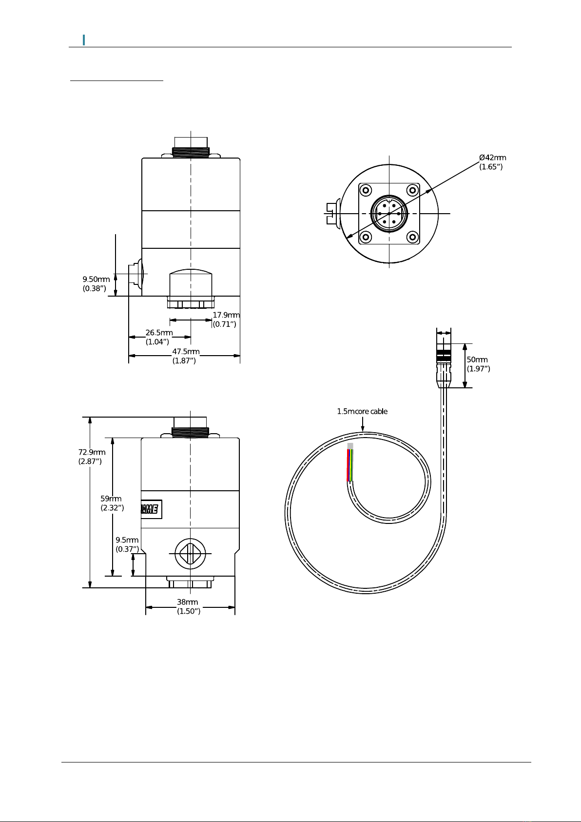
1.1 Gas Pressure Sensor
IP
65
NEMA
4
Housing & Lid
Aluminium
Power Consumption
0.1 Watts
Mounting
Breather hole to be piped or used as differential pressure for IP65/NEMA 4
Installation
Sensor should be installed vertically
Operating Temp.
-25OC to 85OC (-13OF to 185OF)
Part No.
Min. Pressure
Max. Pressure
Zero Range
mbar
“wg
PSI
mbar
“wg
PSI
mbar
“wg
PSI
MM80006
Digital
-68
-27
-1
68
27
1
-1.36 to 1.36
-0.54 to 0.54
-0.02 to 0.02
Analogue
12.5
5
0.18
65
25
1
-2.5 to 1.25
-1.0 to 0.5
-0.04 to 0.02
MM80008
Digital
-344
-138
-5
344
138
5
-6.88 to 6.88
-2.76 to 2.76
-0.1 to 0.1
Analogue
52
25
0.75
340
135
5
-12.5 to 6.25
-5.0 to 2.5
-0.2 to 0.1
MM80011
Digital
-1034
-415
-15
1034
415
15
-20.68 to 20.68
-8.3 to 8.3
-0.3 to 0.3
Analogue
115
50
1.8
750
300
11
-30.0 to 15.0
-12.0 to 6.0
-0.44 to 0.22
MM80012
Digital
-2068
-831
-30
2068
831
30
-41.36 to 41.36
-16.62 to 16.62
-0.6 to 0.6
Analogue
207
83
3
1380
550
20
-55.0 to 27.6
-22.0 to 11.0
-0.8 to 0.4
MM80014
Digital
-6894
-2770
-100
6894
2770
100
-137.88 to 137.88
-55.4 to 55.4
-2 to 2
Analogue
400
162
6
4000
1620
60
-166.0 to 82.0
-67.0 to 32.0
-2.4 to 1.2
Digital - when used with Mk8 MM, Mini Mk8 MM and Mk8 DTI
Analogue - when used with Mk7 MM
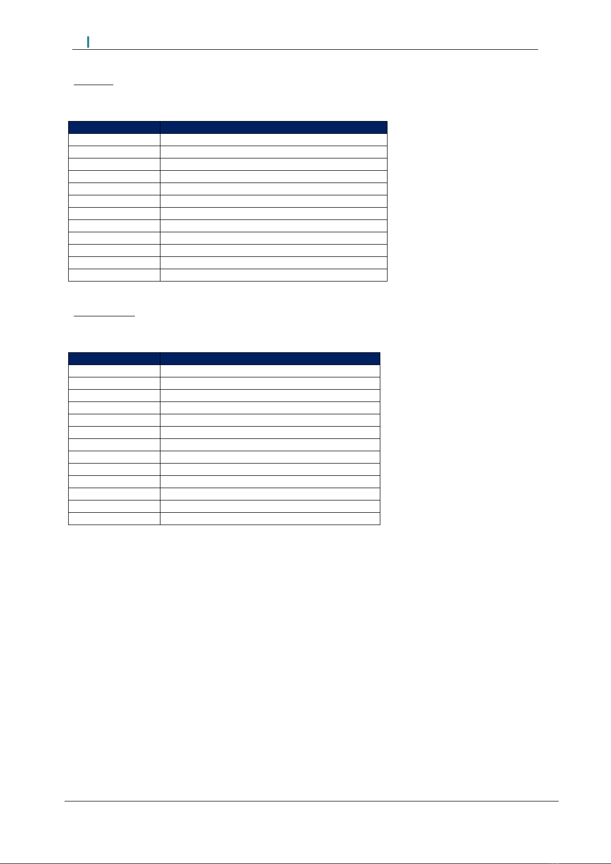
Gas Sensor
Mk8 MM
Mini Mk8 MM
Brown
T31
T29
Purple
T32
T30
Blue
T33
T48
Red
T34
T49
Connect screen at one end only
Drawing No. 9004
Socket
Plug
Circuit board
Pressure
switching unit
Sealing O-rings
1/8” NSP Nylon
plug with
breather hole
Quick connection
screened flying
lead (1.5m)
Plug
¼” Tapered male
nipple
1Sensors
Page | 2
MM Application Possibilities
Gas Pressure Sensor
1Sensors
Page | 3
MM Application Possibilities
Mk8 MM
If the Valve Proving System (VPS) facility is to be used then specific options/parameters must be set.
Option/Parameter
Mk8 MM
125
Fuel pressure sensor mode – fuel 1
126
Fuel pressure sensor mode – fuel 2
127
Fuel pressure sensor mode – fuel 3
128
Fuel pressure sensor mode – fuel 4
129
VPS operation
130
Gas valve configuration
132
Gas valve proving time
133
Maximum pressure change allowed during VPS
134
VPS valve opening time
136
Gas pressure switch – offset lower limit
137
Gas pressure switch – offset upper limit
Parameter 41
Gas pressure units
Mini Mk8 MM
If the Valve Proving System (VPS) facility is to be used then specific options/parameters must be set.
Option/Parameter
Mini Mk8 MM
125
Fuel pressure sensor mode – fuel 1
126
Fuel pressure sensor mode – fuel 2
128
VPS sensor type
129
VPS operation
130
Gas valve configuration
131
Gas pressure units
132
Gas valve proving time
133
Maximum change allowed during proving time
134
VPS valve opening time
136
Gas pressure switch – offset lower limit
137
Gas pressure switch – offset upper limit
138
Gas static line pressure lower limit offset
156
Terminal T82 function
IT IS THE RESPONSIBILITY OF THE COMMISSIONING ENGINEERS TO ENSURE THAT
THE RELEVANT VALVE PROVING SYSTEM STANDARDS ARE ADHERED TO.
1Sensors
Page | 4
MM Application Possibilities
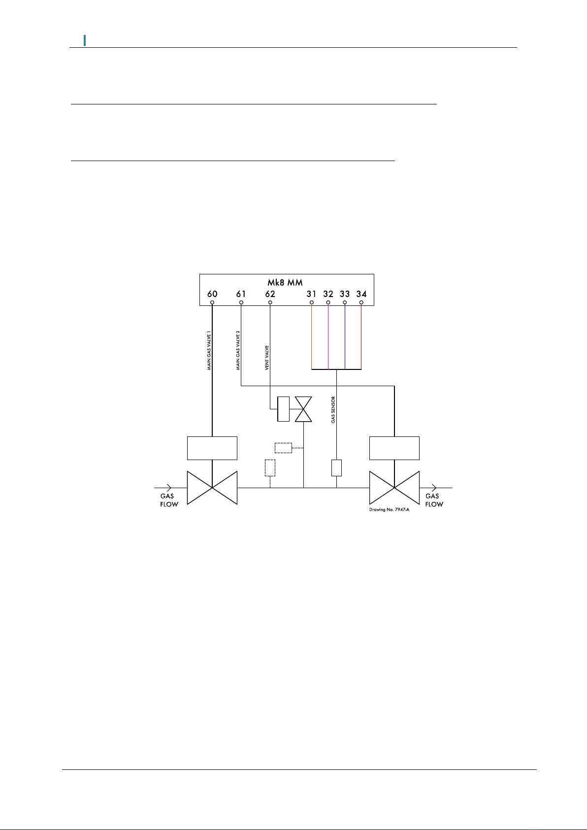
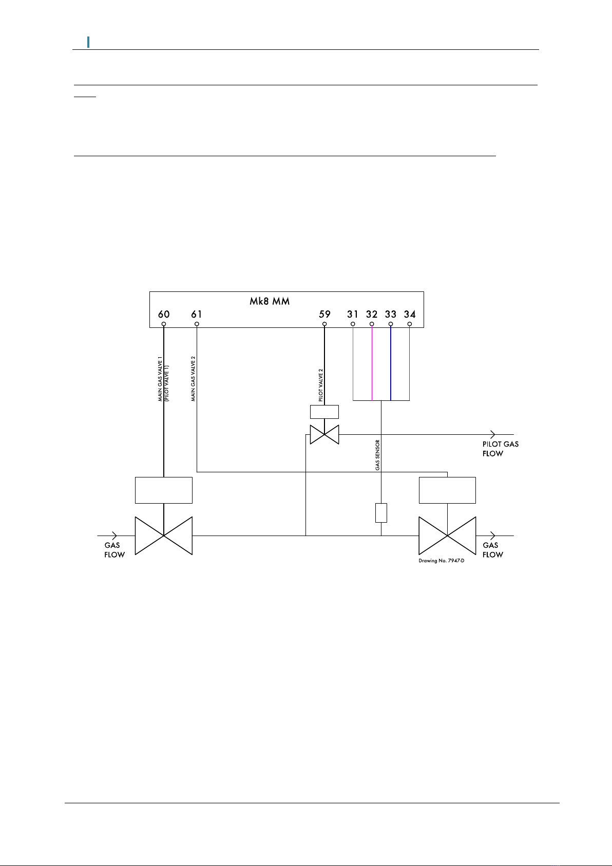
1.1.1 Mk8 MM Valve Proving Schematics
VPS and High/low Pressure Limits using Autoflame Gas Pressure Sensor (3 valves)
Option/ parameter 125 (126, 127, or 128 if fuel 2, 3 or 4) to 1
Option/ parameter 130 to 1 or 2
High/low Pressure Limits using Autoflame Gas Pressure Sensor (3 valves)
Option/ parameter 125 (126, 127, or 128 if fuel 2, 3 or 4) to 2
Option/ parameter 130 to 1 or 2
Note: Please refer to page 3 for full list of VPS options/parameters.

1Sensors
Page | 5
MM Application Possibilities
VPS and High/Low Pressure Limits using Autoflame Gas Pressure Sensor (2 valves)
Option/ parameter 125 (126, 127, or 128 if fuel 2, 3 or 4) to 1
Option/ parameter 130 to 0
High/Low Pressure Limits using Autoflame Gas Pressure Sensor (2 valves)
Option/ parameter 125 (126, 127, or 128 if fuel 2, 3 or 4) to 2
Option/ parameter 130 to 0
Note: Please refer to page 3 for full list of VPS options/parameters.

1Sensors
Page | 6
MM Application Possibilities
VPS and High/Low Pressure Limits using Autoflame Gas Pressure Sensor (3 valves, single valve
pilot)
Option/ parameter 125 (126, 127, or 128 if fuel 2, 3 or 4) to 1
Option/ parameter 130 to 4 or 5
High/Low Pressure Limits using Autoflame Gas Pressure Sensor (3 valves, single valve pilot)
Option/ parameter 125 (126, 127, or 128 if fuel 2, 3 or 4) to 2
Option/ parameter 130 to 4 or 5
Note: Please refer to page 3 for full list of VPS options/parameters.
1Sensors
Page | 7
MM Application Possibilities
VPS and High/Low Pressure Limits using Autoflame Gas Pressure Sensor (2 valves, single valve
pilot)
Option/ parameter 125 (126, 127, or 128 if fuel 2, 3 or 4) to 1
Option/ parameter 130 to 3
High/Low Pressure Limits using Autoflame Gas Pressure Sensor (2 valves, single valve pilot)
Option/ parameter 125 (126, 127, or 128 if fuel 2, 3 or 4) to 2
Option/ parameter 130 to 3
Note: Please refer to page 3 for full list of VPS options/parameters.

1Sensors
Page | 8
MM Application Possibilities
External VPS
Option / parameter 125 (126, 127, or 128 if fuel 2, 3 or 4) to 3
Note: Please refer to page 3 for full list of VPS options/parameters.
1Sensors
Page | 9
MM Application Possibilities
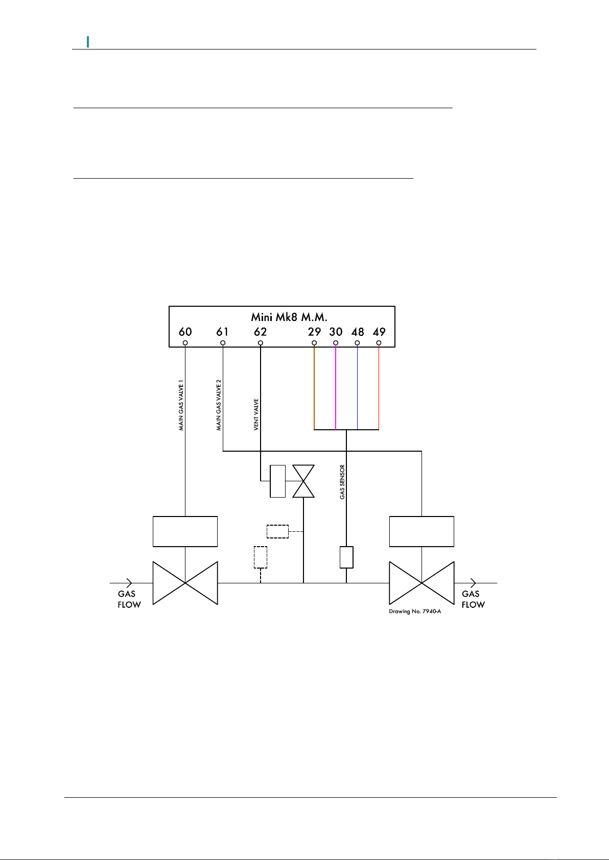
1.1.2 Mini Mk8 MM Valve Proving Schematics
VPS and High/Low Pressure limits using Autoflame Gas Pressure Sensor (3 valves)
Option/ parameter 125 (126 if fuel 2) to 1
Option/ parameter 128 to 1
Option/ parameter 130 to 1 or 2
High/Low Pressure Limits using Autoflame Gas Pressure Sensor (3 valves)
Option/ parameter 125 (126 if fuel 2) to 2
Option/ parameter 128 to 1
Option/ parameter 130 to 1 or 2
Note: Please refer to page 3 for full list of VPS options/parameters.
1Sensors
Page | 10
MM Application Possibilities
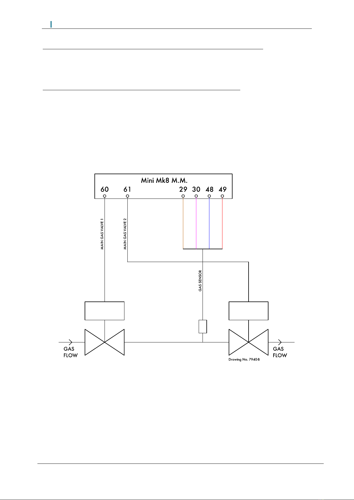
VPS and High/Low Pressure limits using Autoflame Gas Pressure Sensor (2 valves)
Option/ parameter 125 (126 if fuel 2) to 1
Option/ parameter 128 to 1
Option/ parameter 130 to 0
High/Low Pressure Limits using Autoflame Gas Pressure Sensor (2 valves)
Option/ parameter 125 (126 if fuel 2) to 2
Option/ parameter 128 to 1
Option/ parameter 130 to 0
Note: Please refer to page 3 for full list of VPS options/parameters.

1Sensors
Page | 11
MM Application Possibilities
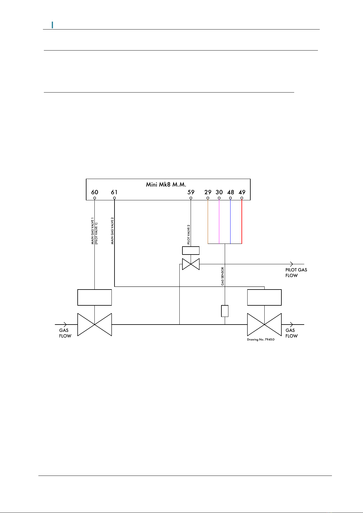
VPS and High/Low Pressure limits using Autoflame Gas Pressure Sensor (3 valves, single valve pilot)
Option/ parameter 125 (126 if fuel 2) to 1
Option/ parameter 128 to 1
Option/ parameter 130 to 4 or 5
High/Low Pressure Limits using Autoflame Gas Pressure Sensor (3 valves, single valve pilot)
Option/ parameter 125 (126 if fuel 2) to 2
Option/ parameter 128 to 1
Option/ parameter 130 to 4 or 5
Note: Please refer to page 3 for full list of VPS options/parameters.
1Sensors
Page | 12
MM Application Possibilities
VPS and High/Low Pressure limits using Autoflame Gas Pressure Sensor (2 valves, single valve pilot)
Option/ parameter 125 (126 if fuel 2) to 1
Option/ parameter 128 to 1
Option/ parameter 130 to 3
High/Low Pressure Limits using Autoflame Gas Pressure Sensor (2 valves, single valve pilot)
Option/ parameter 125 (126 if fuel 2) to 2
Option/ parameter 128 to 1
Option/ parameter 130 to 3
Note: Please refer to page 3 for full list of VPS options/parameters.
Note: Void to boiler phase is done via the pilot valve.
1Sensors
Page | 13
MM Application Possibilities
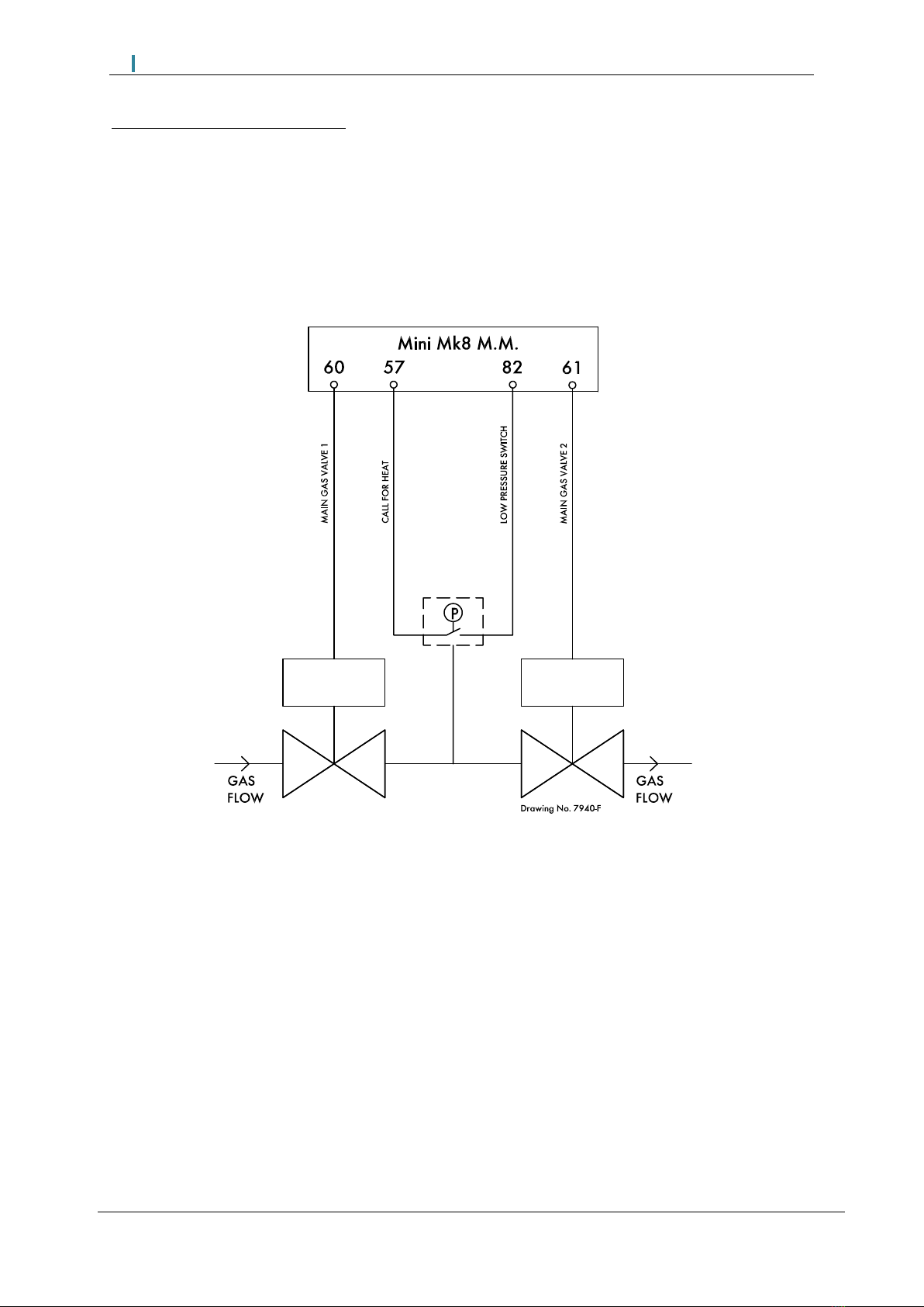
VPS using a Low Pressure Switch
Option/ parameter 125 (126 if fuel 2) to 1
Option/ parameter 128 to 0
Option/ parameter 156 to 1
Note: Please refer to page 3 for full list of VPS options/parameters.
Note: During VPS, the input on terminal 82 should be on during the VPS air proving and gas proving
phases, and at all other VPS phases, the input to terminal 82 should be off. The pressure detected is
the static line pressure, so the pressure switch should be set at a value just below this line pressure.
When the burner is firing, terminal 82 is not checked.
1Sensors
Page | 14
MM Application Possibilities
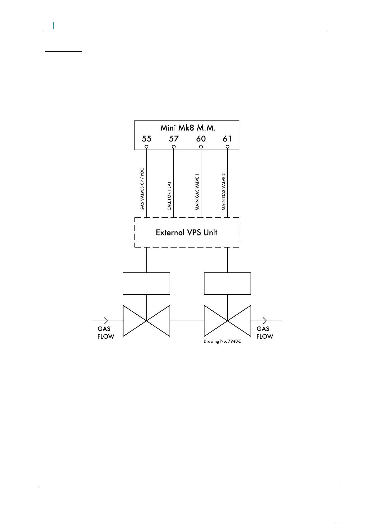
External VPS
Option/ parameter 125 (126 if fuel 2) to 3
Note: Please refer to page 3 for full list of VPS options/parameters.
This manual suits for next models
7
Other AUTOFLAME Accessories manuals

Popular Accessories manuals by other brands

C.P. Electronics
C.P. Electronics SPIR-F/C-IP installation guide

Silvercrest
Silvercrest SPB 5200 A1 Operating instructions and safety instructions

Concept2
Concept2 DV7420 instruction manual

Fire-Lite
Fire-Lite CHG-120 series instruction sheet

MD SPORTS
MD SPORTS SOC054_017E Assembly instructions

Remo+
Remo+ REMOBELL quick start guide


1 BY ONE
1 BY ONE O00QH-050 instruction manual

Pegasus Astro
Pegasus Astro FocusCube operating manual

Kieback&Peter
Kieback&Peter DU0/5 manual

Closet Maid
Closet Maid In-Cabinet Trash Pull-Out 3185 Use and care guide

Metalcraft
Metalcraft GR-4100 Mounting and user instructions

New Air
New Air AB1200BC1 owner's manual