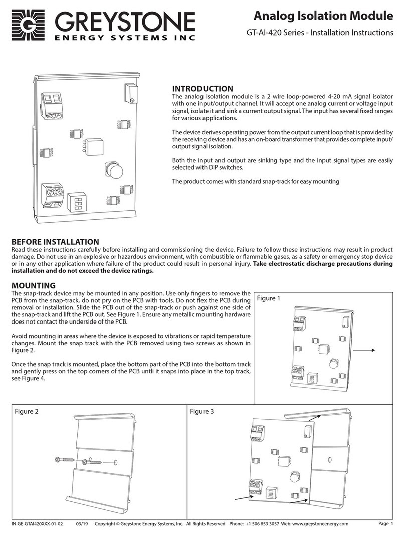
Automation Controls Group UniDrive SCC-3 Guide

Installation and
Troubleshooting Guide
UniDrive
®
Smart Conveyor Control
Generation III (SCC-3)
Product 110515

Copyright ©2013-2018 Automation Controls Group, Inc. A division of MEC Companies, Inc. All Rights Reserved.
This document is the property of Automation Controls Group, Inc., and may not be reproduced in hole or in part ithout prior ritten approval.
Other trademarks and service marks used or referenced in this document are the property of their respective o ners.
C O N T E N T S
1
Product Diagram
4
2
General Notes
5
2.1
Motor Cable & Connection Header ......................................................................................................................... 5
2.2
+24V DC Power Input Connection Header ........................................................................................................... 5
2.3
PNP ensor Connection Header .............................................................................................................................. 5
2.4
mart/User Input-Output Connection Header ..................................................................................................... 5
2.5
Feedback LED Indicators............................................................................................................................................ 6
2.6
Configuration witches ............................................................................................................................................... 6
2.7
Upstream Cable Connection ..................................................................................................................................... 6
2.8
Downstream Cable Connection ............................................................................................................................... 6
2.9
Mounting Plate/Heat ink ......................................................................................................................................... 6
2.10
Cover ................................................................................................................................................................................. 6
3
Installation Guide
6
3.1
Mount the Control ......................................................................................................................................................... 7
3.2
elect a Motor ................................................................................................................................................................ 7
3.3
elect a peed ............................................................................................................................................................... 7
3.4
Configure the Location ................................................................................................................................................ 7
3.5
Configure the Operating Mode ................................................................................................................................. 7
3.6
Configure the Rotation ................................................................................................................................................ 7
3.7
Configure Communications ....................................................................................................................................... 7
3.8
Connect User Input/Output ....................................................................................................................................... 8
3.8.1
Entry Zone ................................................................................................................................................................... 8
3.8.2
Intermediate Zone .................................................................................................................................................... 8
3.8.3
Exit Zone ...................................................................................................................................................................... 8
3.8.4 Braking & Zero Motion Hold (ZMH)……………………………………………………………………………………….. 9
3.8.5 lug & Reverse lug Input Operation………………………………………………………..….……………………….. 9
3.8.6 Other Modes of Operation……………………………………………………………………………………………………...9
4
Special Functions
9
4.1
Zone Hold Input…………………………………………………………………………………………………….…………………9
4.2
Configuring an CC-3 as a BMC……………………………………………………………………………………….……….9
4.3
earch and Rescue ...................................................................................................................................................... 9
4.3.1
During Power Up ....................................................................................................................................................... 9
4.3.2
After Discharge of a Parcel from the Downstream Edge of a Zone……………………………………...…..9
4.3.3
After Removal of a lug ignal…………………………………………………………………………………………….10
4.3.4
After Removal of a Rev lug ignal………………………………………………………………………………………10
5
Diagnostics Troubleshooting
10
5.1
Feedback LEDs ........................................................................................................................................................... 10
5.1.1
Fuse LED (Red)……………………………………………………………………………………………………………………10
5.1.2
Fault LED (Red)…………………………………………………………………………………………………………………..10
5.1.3
Motor LED (Amber) ................................................................................................................................................ 10
5.1.4
Power LED (Green) ................................................................................................................................................ 10
5.2
Firmware Version Display ....................................................................................................................................... 10
5.3
6-Wire Modular Cable Orientation ……………………………………………………………………………………….…11
5.4
Additional Assistance……………,,,,,,,,,,,,,,,,,,,,,,,,,,,,,,,,,,,,,,,,,,,,,,,,,,,,,,,,,,,,,,,,,,,,,,,,,,,,,,,,,,,,,,,,,,,,,,,,,,,,,,,,,,,,,,,,,,,,,,,,11

SCC-3 Product 110515 Revision 1.3 April 19, 2018 | Pa e 3
L I S T O F F I G U R E S
Figure 1: SCC-3 Controller Components ................................................................................................ 4
Figure 2: Motor Connector Orientation ................................................................................................... 5
Figure 3: Firmware Version Displa Example ....................................................................................... 10
L I S T O F T A B L E S
Table 1: DC Power Inputs Pinout............................................................................................................ 5
Table 2: Sensor Connections Pinout ...................................................................................................... 5
Table 3: Smart PNP Inputs and Outputs Pinout ..................................................................................... 5
Table 4: Configuration Switch Settings ................................................................................................... 6
Table 5: Motor Selection Switch Settings ............................................................................................... 7
Table 6: Operating Speeds ..................................................................................................................... 7
Table 7: Switch 3 Settings for Control Location ...................................................................................... 7
Table 8: Switch 2 Settings for Operating Mode ...................................................................................... 7

SCC-3 Product 110515 Revision 1.3 April 19, 2018 | Pa e 4
1
Product Diagram
1) Motor Connection Header
2) +24V DC Power Input Header (plug included)
3) PNP Sen or Connection Header (plug included)
4) Smart/U er Input-Output Connection Header (plug included)
5) Feedback LED Indicator
6) Configuration Switche
7) Up tream Peer-to-Peer NPN RJ-25 Connection
8) Down tream Peer-to-Peer NPN RJ-25 Connection
9) Mounting Plate/Heat Sink
10) Cover
NOTE: This guide refers to the components by their item number as listed above.
Figure 1: SCC-3 Controller Components

SCC-3 Product 110515 Revision 1.3 April 19, 2018 | Pa e 5
2
General Notes
2.1
Motor Cable & Connection Header
C UTION: Use of extension cables may cause permanent
damage and will void the product warranty.
UniDrive® motors and controls are designed to operate together as
a complete and compatible drive system. Proper care must be
taken to prevent damage to the Automation Controls Group (ACG)
control motor and connection cable.
UniDrive® motors come with a permanent built-in power & control
cable having either a 20 inch or a 72 inch cable length for connection
solely to compatible ACG controls. See the specific UniDrive® motor
or PowerCube™ specification sheet for details. Do not attempt to
connect the motor cable to any control other than one
manufactured by Automation Controls Group (ACG).
Do not put tension on the motor cable connection. Tension cable
strain or stress on the motor cable could deform the pressure
contacts inside the motor connector. This could result in
intermittent motor connections and in extreme cases may bend the
pins on the control board.
The motor connector is designed to be installed on the control and
then remain connected to the control for the life of the motor. Do
not remove the motor connector except in the rare in tance of
motor or control replacement. The motor connector mu t not be
u ed a a power on/off witch.
If the motor connector must be removed from the control remove
the connector slowly by carefully lifting while also gently rocking the
connector from side-to-side (“inch-worming”) in order to lift the
connector off the control pins a little at a time. Lift the motor
connector straight up by grasping the sides of the motor connector
and avoid using the cable strain relief as a handle to lift the
connector.
Power to the control and motor must be removed by turning off or
removing input power at the source (Lock-out & Tag-out preferred).
Alternately by disconnecting the +24V DC Power Input Connection
Header (see section 2.2 below) on the control. The motor
connector mu t not be u ed a a power on/off witch.
Do not disassemble the motor cable. If the motor cable becomes
damaged obtain a replacement motor.
NOTE: The motor connection cable must be oriented on the
control header pins as shown in the figure below.
2.2
+24V DC Power Input Connection Header
C UTION: Power must be applied with proper polarity to
avoid potentially damaging the controller. Follow the
pinout shown in Table 1 below.
A 2-pin Phoenix PT1.2/2-PVH-3.5 plug is supplied. The SCC-3 operates
off a +22 to +28 Volt DC power supply. The control reads the
configuration switches only when the unit is powering up. Make the
power connection only after all other connections have been made.
Pin: Signal:
1 +22 to +28 Volts DC
2 DC Ground
Table 1: DC Power Inputs Pinout
NOTE: When adjacent zones are operating from separate
power supplies you should connect their 0VDC grounds.
However, do not connect their positive voltage pins together.
2.3
PNP Sen or Connection Header
C UTION: If the sensor is mounted on non-conductive
equipment, such as a plastic slide, ground the body of
the sensor to provide a non-destructive discharge path in
the event of a static electric shock.
A 3-pin Phoenix PT1.5/3-PVH-3.5 plug is supplied.
Pin: Signal:
1 DC Ground
2 Input From Sensor
3 +VDC*
Table 2: Sensor Connections Pinout
*NOTE: The +VDC signal for pin number 3 is fused with a 0.1
mp self-resetting fuse. Use of this output for any purpose
that requires more than 0.1 mps will cause the fuse to
open and temporarily disable this output.
2.4
Smart U er Input-Output Connection Header
A 7-pin Phoenix PT1.5/7-PVH-3.5 plug is supplied. Function depends
upon the controller’s current configuration based on the
configuration switch settings. If the smart I/O is not being used
leave the connector in place to avoid accidentally shorting the pins.
Pin: Description:
1 Smart Input 1*
2 Slug Input*
3 Rev Slug Input*
4 Smart Output 2
Analog Input +
6 Analog Input –
7 Zone Hold Input*
Table 3: Smart PNP Inputs and utputs Pinout
*NOTE: Smart I/O is active above +18 Volts DC (PNP)
Figure 2: Motor Connector rientation

SCC-3 Product 110515 Revision 1.3 April 19, 2018 | Pa e 6
2.5
Feedback LED Indicator
The control board contains four (4) LED feedback indicators:
One (1) Red Fuse LED
One (1) Red Fault LED
One (1) Amber Motor LED
One (1) Green Power LED
To learn more see 5.1 Feedback LEDs and 5.2 Firmware
Version Display.
2.6
Configuration Switche
The control reads the configuration switches only when the
unit is powering up. To change a setting disconnect power
set the switch and then reconnect power. The OFF position
is to the Left and the ON position is to the Right as seen in
Figure 1: SCC-3 Controller Components. Switch descriptions
are given in the following table:
Switch:
Description: OFF Setting ON Setting
1 Rotation Direction Counter-Clockwise* Clockwise*
2 Mode ZPA/ZIP ZPA ZIP
3 Zone Type Exit/Xport Entry/Xport
4 Target Speed
(with SW , SW6)
See Table 6: Operating Speeds. Target Speed
(with SW4, SW6)
6 Target Speed
(with SW4, SW )
7 Motor Selection 100W24 12 W24
8 Braking & ZMH Enabled Disabled
Table 4: Configuration Switch Settings
*NOTE: The direction of rotation is defined when viewed
from the back side of the motor with the shaft extending
away from the viewer.
NOTE: The switches are read during power-up only.
Set the switches, and then connect power to the board.
2.7
Up tream Cable Connection
This connector is intended for use with a 6-wire modular phone
cable to connect to an adjacent upstream SCC board. See Section
5.3 for information on the cable. The cable is not provided.
2.8
Down tream Cable Connection
This connector is intended for use with a 6-wire modular phone
cable to connect to an adjacent downstream SCC board. See
Section 5.3 for information on the cable. The cable is not provided.
2.9
Mounting Plate/Heat Sink
This component is for mounting the control assembly to the
conveyor frame using two ¼ inch or 0.25 in (6.35 mm) bolts to keep
the controller cooler.
C UTION: If mounting the control on a curved section of
conveyor, use washers between the mounting plate and
the conveyor frame. This is to assure that the mounting
plate is not distorted, causing damage to the enclosed
printed circuit board assembly.
2.10
Cover
C UTION: Removal of the cover will void the warranty.
The cover does not make the controller waterproof or
dustproof.
The cover can help reduce the severity of damage to the
controller from foreign objects.
3
Installation Guide
This section describes how to install and use the SCC-3 and
UniDrive® Motor in the most common configurations. For
additional information refer to the application notes.
1. Mount the Control
2. Select a Motor
3. Select a Speed
4. Configure the Location
5. Configure the Operating Mode
6. Configure the Rotation
7. Configure Communication
8. Connect U er Input/Output

SCC-3 Product 110515 Revision 1.3 April 19, 2018 | Pa e 7
3.1
Mount the Control
Mount the control in a location where the motor cable
reaches the connection header without putting strain on the
cable connector or the header.
3.2
Select a Motor
Select the motor you will be using. Properly match the
control settings to the motor in use to deliver the best and
most predictable performance.
SW8: SW7: Motor: omments:
OFF OFF 100W24 Previously STD
OFF ON 12 W24 Previously HO.
Table 5: Motor Selection Switch Settings
3.3
Select a Speed
Three switches determine the operating speed making it
simple to match speeds in multiple zones. The actual speed
selected also depends on the motor that you selected in the
previous step so set those switches first.
There is also an option to use a 0-10 V differential input for
remote dynamic speed adjustment while the system is
running.
Switches
:
Speed
Selection (RPM)
:
SW6 SW5 SW4 100W24 125W24
OFF OFF OFF 280 3 0
OFF OFF ON 248 310
OFF ON OFF 216 270
OFF ON ON 184 230
ON OFF OFF 1 2 190
ON OFF ON 120 1 0
ON ON OFF 88 110
ON ON ON 6 70
Table 6: perating Speeds
3.4
Configure the Location
Identify the location of the control and then set Switch 3.
If this control is placed at the entry end of the conveyor
section where objects are loaded set Switch 3 to the ON
position.
If this control is placed between two other SCC-3
controls set Switch 3 to either ON or OFF.
If this control is placed at the exit end of the conveyor
section where objects are discharged set Switch 3 to the
OFF position.
Entry: In Between: Exit:
ON ON or OFF OFF
Table 7: Switch 3 Settings for Control Location
3.5
Configure the Operating Mode
Identify the operating mode that this section of conveyor will
use for transporting objects and then set Switch 2.
If the conveyor will be operating in the most
conservative conventional Zero-Pressure Accumulation
(ZPA) mode set Switch 2 to the OFF position.
If the conveyor will be operating in the higher
throughput enhanced accumulation ZIP mode set
Switch 2 to the ON position.
If the conveyor will be operating in the Slug or Slug
Reverse mode or as a stand-alone unit Switch 2 may be
set to the ON or OFF position because the Slug and Slug
Reverse inputs override all of the accumulation logic.
ZPA: Slug, Slug Reverse,
or Stand-alone: ZIP:
OFF OFF or ON ON
Table 8: Switch 2 Settings for perating Mode
3.6
Configure the Rotation
Identify the proper direction of rotation for the motor shaft
in order to move objects from the upstream (entry) end of
the conveyor towards the downstream (exit) end of the
conveyor. The direction of rotation is defined when viewed
from the back side of the motor with the shaft extending
away from the viewer.
For clockwise rotation set Switch 1 to the ON position.
For counter-clockwise rotation set Switch 1 to OFF.
3.7
Configure Communication
Make the peer-to-peer communication connections. These
controls pass request and permission signals between adjacent
zones over 6-wire modular phone cables. See Section 5.3 for
information on the cable orientation.
At the exit end of the conveyor do not connect the
phone cable to the Downstream Peer-to-Peer NPN RJ-25
Connection (item 8).
Connect one end of a 6-wire phone cable to the
Upstream Peer-to-Peer NPN RJ-25 Connection (item 7)
and then connect the other end of the phone cable to
the downstream phone jack on the adjacent upstream
control.
At each adjacent intermediate control connect another
6-wire phone cable to the Upstream Peer-to-Peer NPN
RJ-25 Connection (item 7) and then connect the other
end of that cable to the downstream phone jack on the
adjacent upstream control.
At the entry end of the conveyor do not connect a
phone cable to the Upstream Peer-to-Peer NPN RJ-25
Connection (item 7).

SCC-3 Product 110515 Revision 1.3 April 19, 2018 | Pa e 8
3.8
Connect U er Input/Output
3.8.1
Entry Zone
1.
Use Smart 1 (a PNP input called a request) to notify the
control that there is a parcel ready for input to the zone. If
the zone is not already occupied when this signal is active it
will cause the zone to run. The signal may be provided by
any number of alternative sources such as a PLC a simple
switch a photo sensor etc. as long as the input voltage is
positive and between 18 volts and 29 volts DC.
2.
Use Smart 2 (a PNP output called permission) to notify an
external device that the zone is empty and ready to receive a
parcel.
3.
Use Slug (a PNP input) to override all logic internal to the
control and force this zone to run regardless of whether it is
occupied or empty.
NOTE: When this signal is active, parcels are pushed into
the next downstream zone even if it is already occupied.
4.
Use Rev Slug (a PNP input) in one of two ways:
Alone: Assert it by itself to cause the zone to coast. The
motor will not be energized and will not provide any
active braking power.
In Combination: Assert it in combination with the Slug
input to override all logic internal to the control and force
this zone to run in the reverse direction regardless of
whether it is occupied or empty.
NOTE: When this signal is active, parcels are pushed out
of the upstream end of the zone regardless of the
availability of any upstream device to accept the parcel.
In this scenario, if there is nothing there, any parcels
could potentially fall to the floor.
5.
Use Analog In+ and Analog In- in combination to provide a
0-10 V differential signal that overrides the settings on the
speed control switch. If the voltage differential is less than
0.5 VDC the control ignores the input and the speed control
switch settings will prevail. If the signal is 9.5 VDC or higher
the control operates the motor at its maximum speed
setting of 280 or 350 RPM depending on the motor selected.
3.8.2
Intermediate Zone
An intermediate zone is between two adjacent SCC-3
controlled zones.
NOTE: Do not connect anything to Smart Input 1 or
Smart Output 2.
1.
Use Slug (a PNP input) to override all logic internal to the
control and force this zone and all adjacent upstream zones
to run regardless of whether they are occupied or empty.
Note that when this signal is active parcels will be pushed
into the next downstream zone even if it is already occupied.
2.
Use Rev Slug (a PNP input) in one of two ways:
Alone: Assert it by itself to cause this zone and all adjacent
upstream zones to coast. The motor will not be energized
and will not provide any active braking power.
In Combination: Assert it in combination with the Slug
input to override all logic internal to the control and force
this zone and all adjacent upstream zones to run in the
reverse direction regardless of whether they are occupied
or empty.
NOTE: When this signal is active, parcels are pushed out
of the upstream end of the conveyor regardless of the
availability of any upstream device to accept the parcels.
In this scenario, if there is nothing there, any parcels
could potentially fall to the floor.
3.
Use Analog In+ and Analog In- in combination to provide a
0-10 V differential signal that overrides the settings on the
speed control switch. If the voltage differential is less than
0.5 VDC the control ignores the input and the speed control
switch settings will prevail. If the signal is 9.5 VDC or higher
the control operates the motor at its maximum speed
setting of 280 or 350 RPM depending on the motor selected.
3.8.3
Exit Zone
1. Use Smart 1 (a PNP input called permission) to notify the
control that it has permission to discharge a parcel. The
signal may be provided by any number of alternative sources
such as a PLC a simple switch a photo sensor etc. as long as
the input voltage is positive and between 18 volts and 29
volts DC. Note that when permission is removed the zone
will attempt to stop any discharge that may be in process.
2. Use Smart 2 (a PNP output called request) to notify an
external device that the zone is occupied and ready to
discharge a parcel.
3. Use Slug (a PNP input) to override all logic internal to the
control and force this zone and all upstream zones to run
regardless of whether they are occupied or empty.
NOTE: When this signal is active, parcels will be pushed
off the end of the conveyor if there is nothing in place to
receive them.
4.
Use Rev Slug (a PNP input) in one of two ways:
Alone: Assert it by itself to cause the zone and all
upstream zones to coast. The motors will not be
energized and will not provide any active braking power.
In Combination: Assert it in combination with the slug
input to override all logic internal to the control and force
this zone and all upstream zones to run in the reverse
direction regardless of whether they are occupied or
empty.
NOTE: When this signal is active, parcels are pushed out
of the upstream end of the zone regardless of the
availability of any upstream device to accept the parcels.
In this scenario, if there is nothing there, any parcels
could potentially fall to the floor.
5.
Use Analog In+ and Analog In- in combination to provide a
0-10 V differential signal that overrides the settings on the
speed control switch. If the voltage differential is less than
0.5 VDC the control will ignore the input and the speed
control switch settings will prevail. If the signal is 9.5 VDC or
higher the control will operate the motor at its maximum
speed setting of 280 or 350 RPM depending on the motor
selected.

SCC-3 Product 110515 Revision 1.3 April 19, 2018 | Pa e 9
3.8.4
Braking & Zero Motion Hold (ZMH)
When DIP Switch 8 is placed in the OFF position motor
dynamic braking will be used to bring the motor to a stop as
quickly as possible. When DIP switch 8 is in the OFF position
Zero Motion Hold (ZMH) will also be active so that if the
motor shaft continues rotating due to inertia increasing
current will be applied to the three motor phase windings in
an attempt to hold the motor shaft at the requested stop
position.
When DIP Switch 8 is placed in the ON position the motor
will be allowed to coast and no motor braking will be
applied.
3.8.5
Slug & Rever e Slug Input Operation
1. Use Slug (a PNP input) to override all logic internal to the
control and force this zone and all upstream zones to run
regardless of whether they are occupied or empty. Slug is
sometimes also referred to as Jog
NOTE: When this signal is active, parcels will be
pushed off the end of the conveyor if there is
nothing in place to receive them.
2. Use Rev Slug (a PNP input) in one of two ways:
Alone: Assert it by itself to cause the zone and all
upstream zones to coast. The motors will not be
energized and will not provide any active braking power.
In Combination: Assert it in combination with the slug
input to override all logic internal to the control and force
this zone and all upstream zones to run in the reverse
direction regardless of whether they are occupied or
empty.
NOTE: When this signal is active, parcels are pushed
out of the upstream end of the zone regardless of
the availability of any upstream device to accept the
parcel. In this scenario, if there is nothing there, any
parcels could potentially fall to the floor.
______________________________________________________
3.8.6
Other Mode of Operation
If you need to do something other than those things listed
above please contact either our Sales or Application
Engineering Departments for assistance at (619) 677-6530.
4
Special Functions
4.1
Zone Hold Input
When the zone hold input (I/O pin 7) goes active prior to an
object reaching the primary (downstream-edge) sensor then
that object will be held in that zone and will not exit while the
zone hold signal remains active.
All objects in the upstream zones will also be held while the
zone hold input is active.
When an object is actively exiting the zone hold input will have
no effect on that object exiting.
4.2
Configuring an SCC-3 a a BMC
In certain applications it may be necessary to eliminate the 2.5
second motor run-on feature which is a part of the Search &
Rescue function (see section 4.3). To accomplish this the SCC-3
control can be configured as a Basic Motor Control (BMC) or
standalone motor control. To accomplish this implement the
following steps;
1) Place Control DIP switch 3 in the ON position (slide the
switch to the right)
2) On the GREEN 3-pin sensor connector wire the sensor
input (center pin) to the sensor +voltage (pin on the right).
3) Apply a 24Vdc signal to the Slug input (I/O pin 2) to start
and stop the motor
4) When the Slug input goes high then I/O pin 4 will go high
to indicate that the motor is running
4.3
Search and Re cue
This function has been added to the control in order to avoid
situations where parcels could become stranded between
photo sensors creating a nuisance at the very least. The
function works under the following circumstances:
During Power Up
After Discharge of a Parcel from the Downstream Edge of a Zone
After Removal of a Slug Signal (if Rev Slug is Not Active)
After Removal of a Rev Slug Signal (if Slug is Not Active)
4.3.1
During Power Up
When the power is off parcels are not tracked. When power is
first applied each control goes through a self-check and report its
firmware revision as described in 5.2 Firmware Version Display.
Beginning at the Exit end and then flowing zone by zone after very
brief intervals to avoid creating high inrush current at the power
supply each zone then runs for up to 2.5 seconds or until a parcel
arrives at the respective zone sensor whichever comes first.
In this fashion any parcels that may have been stranded between
sensors when power was removed are discovered and will then
be processed by the conveyor in either ZPA or ZIP control mode as
determined by the switch settings.
NOTE: 2.5 seconds is a nominal time period. The actual
time is adjusted up if zones are set to a lower than
maximum speed. For example, if a zone is set to half its
maximum speed, the run time is doubled to 5.0 seconds.
4.3.2
After Di charge of a Parcel from the
Down tream Edge of a Zone
It is not unusual for operators who are manually loading parcels
onto a conveyor to place two small parcels in a single zone. If the
zone stopped immediately after a parcel passed its downstream
sensor the second parcel could become stranded. Therefore each
zone will operate for up to 2.5 seconds after these events. When
the zone is already running very little additional power is
consumed. This is a local function that directly affects only the
zone that just discharged its parcel.

SCC-3 Product 110515 Revision 1.3 April 19, 2018 | Pa e 10
4.3.3
After Removal of a Slug Signal
(If Rev Slug is Not Active)
During Slug mode of operation parcels are not tracked by the
system logic. Some parcels will likely be between sensors at the
time the Slug signal is removed.
Beginning with the zone where the Slug signal was asserted and
cascading upstream each zone will run for up to 2.5 seconds
until either the time expires or a parcel is discovered.
4.3.4
After Removal of a Rever e Slug Signal
(If Slug is Not Active)
Since Reverse (Rev) Slug causes the zones to coast parcels that
were in motion will come to rest in more or less random
locations. Beginning with the zone where the Rev Slug signal
was asserted and cascading upstream each zone will run for up
to 2.5 seconds until either the timer expires or a parcel is
discovered.
5
Diagnostics Troubleshooting
5.1
Feedback LED
The SCC-3 provides four (4) LED indicators shown as item 5 in Figure
1: SCC-3 Controller Components. These LEDs are often useful in
diagnosing various wiring and connection problems. If power is
connected there will always be at least one LED illuminated or
flashing. When no LED is illuminated there is no power.
5.1.1
Fu e LED (Red)
C UTION: This robust next-generation fuse will not blow
under normal circumstances. Inspect all wiring
connections to assure that there are no short circuits.
This LED is off under normal circumstances. It illuminates
constantly if the 10 amp replaceable fuse is blown and power is
applied with the proper polarity. The 10 amp fuse on the board is
not user-accessible. If the blown fuse LED is illuminated return
the board to your distributor or supplier for analysis or repair.
NOTE: The control’s on-board fuse is NOT replaceable.
5.1.2
Fault LED (Red)
This LED is off under normal circumstances. If a problem is
detected it provides one of the following five signals:
One (1) fla h in 4 econd : The board has a hardware
problem. Return it to your supplier.
Two (2) fla he in 4 econd : The input voltage is too high.
Reduce the voltage.
Three (3) fla he in 4 econd : The input voltage is too low.
Increase the voltage.
Four (4) fla he in 4 econd : There is a problem with the
motor cable or connection. Check to see that the cable is not
damaged and that all of the wires are secure.
Five (5) fla he in 4 econd : Control over temperature.
Six (6) fla he in 4 econd : Extreme over current.
Con tantly ON: The motor is stalled or the sensor is
continuously blocked. Check for mechanical obstructions.
5.1.3
Motor LED (Amber)
Four fla he in 4 econd : Components on the board
have overheated and the circuit is limiting the power to
the motor to about half (50%) of normal. This problem
will correct itself when the board has cooled adequately.
Check for mechanical obstructions.
Con tantly ON: Motor current is at the maximum
allowed and is being electronically limited. Check for
mechanical obstructions.
Flickering: If the motor starts under significant load the
current may be limited briefly causing the LED to flicker.
If the LED flickers constantly this is an indication that the
motor is operating at its upper limit and may never reach
the full speed. This is not a cause for concern and no
corrective action is required.
5.1.4
Power LED (Green)
Con tantly ON: Power is properly applied as long as the fuse
is not blown.
5.2
Firmware Ver ion Di play
Three (3) of the feedback LEDs are used to communicate
the firmware revision of the control assembly during the
start-up sequence. Each time that power is applied to the
board the green (power) and red (fault) LEDs will turn on
immediately. After 1.0 second the amber LED will flash on
for 0.75 seconds followed by an off period. An off period of
1.5 seconds represents a decimal point separating major
revisions from minor revisions. An example is shown below.
The example sequence above represents firmware revision
1.2. When the red (fault) LED turns off the start-up sequence
has ended and normal operation begins.
Figure 3: Firmware Version Display Example

SCC-3 Product 110515 Revision 1.3 April 19, 2018 | Pa e 11
5.3
RJ25,6-Wire,Modular Cable Orientation, L<10ft
5.4
Additional A i tance
To request the latest revision to our user manual visit our
website at www.automationcontrolsgroup.com.
For additional assistance please contact our National
Sales Manager at (414)-426-6539 or our Application
Engineering Department for assistance at (619) 677-6530.
6
Document Revision History
Rev: Date: Summary:
1.0 Feb 2014 Original Release.
1.1
May 2016 Eliminate reference to 4 0 and 60 RPM
1.2 Apr 2018 Add Zone Hold, BMC Conversion & Cable info
1.3 Apr 2018 Add Braking & ZMH and Appendix Information
Appendix A
ZPA Mode (Standard Sigulation) compared to ZIP Mode
This manual suits for next models
1
Table of contents
Popular Control Unit manuals by other brands
steute
steute SRM 21 Multi Mounting and wiring instructions

emmeti
emmeti T3 Installation and commissioning instructions

HP
HP Synergy 480 Gen9 Maintenance and service guide
GEM
GEM B56 operating instructions

Canford
Canford 58-321 Technical data sheet

Telit Wireless Solutions
Telit Wireless Solutions GE864 DUAL V2 Hardware user's guide
