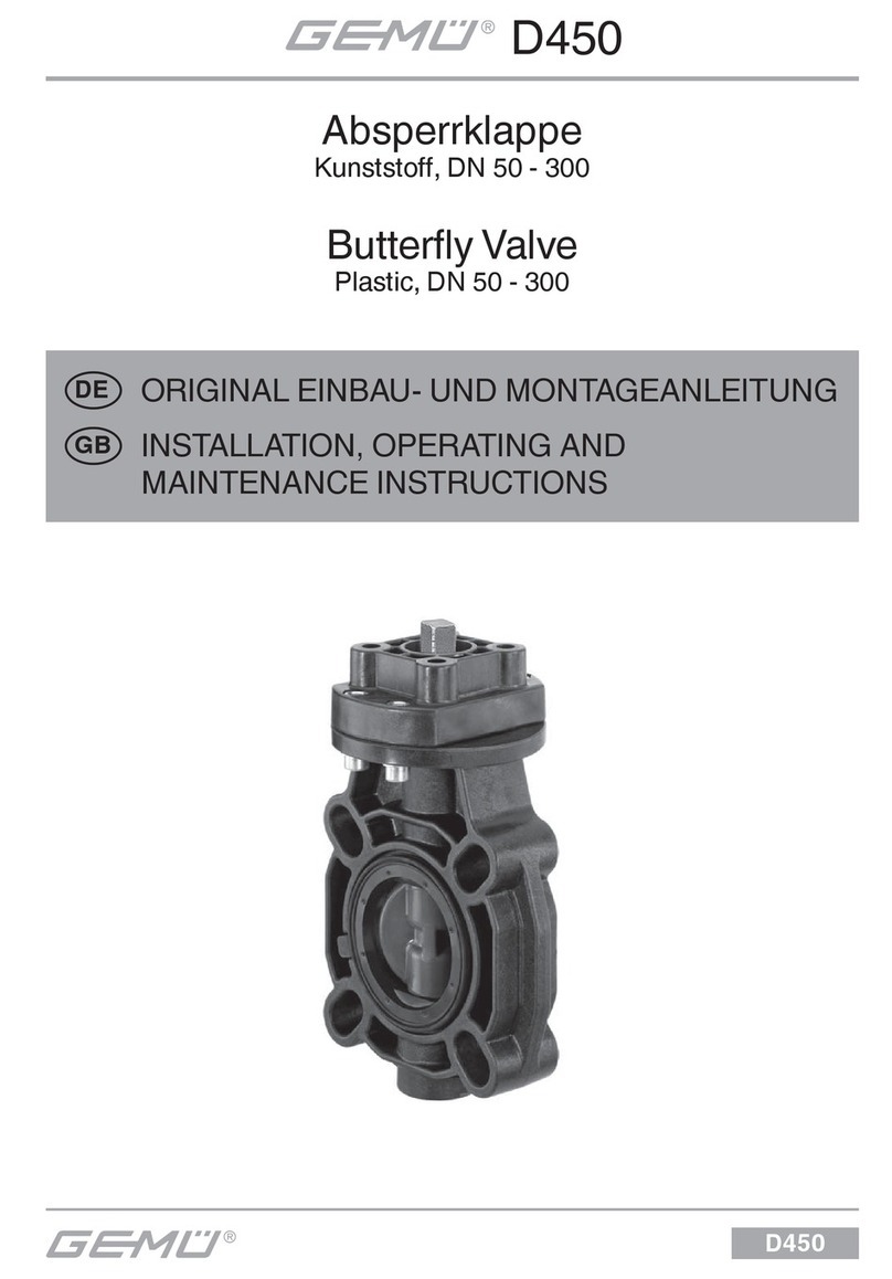
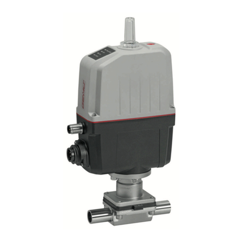
GEM B56 User manual

GEMÜ B56
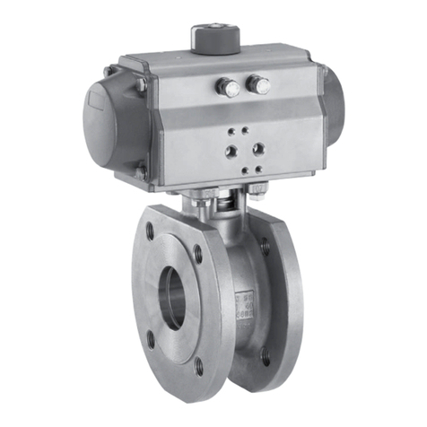
Motorized compact flanged ball valve
Operating instructions
EN
further information
webcode: GW-B56

All rights including copyrights or industrial property rights are expressly reserved.
Keep the document for future reference.
© GEMÜ Gebr. Müller Apparatebau GmbH & Co. KG
07.03.2023
www.gemu-group.com2 / 48GEMÜ B56

Contents
1 General information ............................................. 4
1.1 Information .................................................... 4
1.2 Symbols used ................................................ 4
1.3 Definition of terms ........................................ 4
1.4 Warning notes ............................................... 4
2 Safety information ............................................... 5
3 Product description ............................................. 5
3.1 Construction .................................................. 5
3.2 Pressure-relief hole ....................................... 5
3.3 Control ball .................................................... 6
3.4 Description ..................................................... 6
3.5 Function ......................................................... 6
4 GEMÜ CONEXO .................................................... 6
5 Correct use .......................................................... 7
6 Order data ........................................................... 8
6.1 Ball valve with GEMÜ 9428, 9468 actuator .. 8
6.2 Ball valve with J+J actuator ......................... 10
6.3 Ball valve with Bernard actuator ................... 12
7 Ball valve technical data ...................................... 14
7.1 Medium .......................................................... 14
7.2 Temperature .................................................. 14
7.3 Pressure ......................................................... 14
7.4 Product conformities .................................... 17
7.5 Mechanical data ............................................ 17
8 Technical data of actuator ................................... 18
8.1 GEMÜ 9428, 9468 actuators ......................... 18
8.2 Bernard, J+J actuators ................................. 19
9 Dimensions .......................................................... 20
10 Manufacturer's information .................................. 25
10.1 Delivery .......................................................... 25
10.2 Packaging ...................................................... 25
10.3 Transport ....................................................... 25
10.4 Storage ........................................................... 25
11 Installation in piping ............................................ 25
11.1 Preparing for installation .............................. 25
11.2 Installation with flanged connections .......... 26
12 Electrical connection ........................................... 28
12.1 Connection and wiring diagram – actuator
version 1015 .................................................. 28
12.2 Connection and wiring diagram – actuator
version 2070, 4100, 4200 .............................. 30
13 Limit switches ..................................................... 33
13.1 Setting the limit switch for 1015, 2015 and
3035 ............................................................... 33
13.2 Setting the limit switch for 2070, 4100,
4200 ............................................................... 34
14 Commissioning .................................................... 34
15 Operation ............................................................. 35
15.1 Normal operation .......................................... 35
15.2 Optical position indicator .............................. 35
15.3 Manual override ............................................. 35
16 Troubleshooting .................................................. 37
17 Inspection/maintenance ...................................... 38
17.1 Spare parts .................................................... 39
17.2 General information regarding actuator re-
placement ...................................................... 40
17.3 Replacing the actuator .................................. 40
17.4 Replacing the seals ....................................... 41
18 Removal from piping ............................................ 43
19 Disposal .............................................................. 43
20 Returns ................................................................ 43
21 EU Declaration of Incorporation according to the
EC Machinery Directive 2006/42/EC, Annex II B ... 44
22 EU Declaration of Conformity in accordance with
2014/68/EU (Pressure Equipment Directive) ........ 45
23 EU Declaration of Conformity in accordance with
2014/30/EU (EMC Directive) ................................ 46
24 EU Declaration of Conformity in accordance with
2014/35/EU (Low Voltage Directive) .................... 47
GEMÜ B56www.gemu-group.com 3 / 48

www.gemu-group.com4 / 48GEMÜ B56
1 General information
1.1 Information
- The descriptions and instructions apply to the standard ver-
sions. For special versions not described in this document
the basic information contained herein applies in combina-
tion with any additional special documentation.
- Correct installation, operation, maintenance and repair work
ensure faultless operation of the product.
- Should there be any doubts or misunderstandings, the Ger-
man version is the authoritative document.
- Contact us at the address on the last page for staff training
information.
1.2 Symbols used
The following symbols are used in this document:
Symbol Meaning
Tasks to be performed
Response(s) to tasks
– Lists
1.3 Definition of terms
Working medium
The medium that flows through the GEMÜ product.
1.4 Warning notes
Wherever possible, warning notes are organised according to
the following scheme:
SIGNAL WORD
Type and source of the danger
Possible
symbol for the
specific
danger
Possible consequences of non-observance.
Measures for avoiding danger.
Warning notes are always marked with a signal word and
sometimes also with a symbol for the specific danger.
The following signal words and danger levels are used:
DANGER
Imminent danger!
▶Non-observance can cause death or
severe injury.
WARNING
Potentially dangerous situation!
▶Non-observance can cause death or
severe injury.
CAUTION
Potentially dangerous situation!
▶Non-observance can cause moderate
to light injury.
NOTICE
Potentially dangerous situation!
▶Non-observance can cause damage to
property.
The following symbols for the specific dangers can be used
within a warning note:
Symbol Meaning
Corrosive chemicals!
Hot plant components!
Risk of electric shock!

www.gemu-group.com 5 / 48 GEMÜ B56
2 Safety information
The safety information in this document refers only to an indi-
vidual product. Potentially dangerous conditions can arise in
combination with other plant components, which need to be
considered on the basis of a risk analysis. The operator is re-
sponsible for the production of the risk analysis and for com-
pliance with the resulting precautionary measures and re-
gional safety regulations.
The document contains fundamental safety information that
must be observed during commissioning, operation and main-
tenance. Non-compliance with these instructions may cause:
- Personal hazard due to electrical, mechanical and chemical
effects.
- Hazard to nearby equipment.
- Failure of important functions.
- Hazard to the environment due to the leakage of dangerous
substances.
The safety information does not take into account:
- Unexpected incidents and events, which may occur during
installation, operation and maintenance.
- Local safety regulations which must be adhered to by the
operator and by any additional installation personnel.
Prior to commissioning:
1. Transport and store the product correctly.
2. Do not paint the screws and plastic parts of the product.
3. Carry out installation and commissioning using trained
personnel.
4. Provide adequate training for installation and operating
personnel.
5. Ensure that the contents of the document have been fully
understood by the responsible personnel.
6. Define the areas of responsibility.
7. Observe the safety data sheets.
8. Observe the safety regulations for the media used.
During operation:
9. Keep this document available at the place of use.
10. Observe the safety information.
11. Operate the product in accordance with this document.
12. Operate the product in accordance with the specifications.
13. Maintain the product correctly.
14. Do not carry out any maintenance work and repairs not de-
scribed in this document without consulting the manufac-
turer first.
In cases of uncertainty:
15. Consult the nearest GEMÜ sales office.
3 Product description
3.1 Construction
4
3
2
1
3a
3b
5
C
Item Name Materials
1 Ball valve body 1.4408 / CF8M
2 Pipe connections 1.4408 / CF8M
3 Mounting flange ISO 5211 1.4408 / CF8M
3a Actuator housing cover
Actuator version 1015
Actuator version 2070
Actuator version 4100, 4200
PPO (10% glass fibre
reinforced)
ABS
Aluminium
3b Actuator housing base
Actuator version 1015
Actuator version 2070
Actuator version 4100, 4200
PP (30% glass fibre re-
inforced)
ABS
Aluminium
4 Optical position indicator PP-R natural
Seal PTFE
5 Anti-static unit 1.4408
C CONEXO RFID chip
3.2 Pressure-relief hole
Pressure-relief
hole
3 Product description

www.gemu-group.com6 / 48GEMÜ B56
4 GEMÜ CONEXO
3.3 Control ball
Control ball Code U Code Y Code W
30°
60°
90°
Note: The control ball cannot be retrofitted to standard 2/2-
way bodies at a later date.
3.4 Description
The GEMÜ B56 3-piece 2/2-way metal ball valve is motorized.
It has a plastic actuator housing. A manual override and an
optical position indicator are integrated as standard. The seat
seal is made of PTFE.
3.5 Function
The product is equipped with a top flange in stainless steel. It
has an electric actuator with a powerful DC motor. The reduc-
tion gear in the motor, consisting of a threaded spindle with a
lever, provides the rotation through 90°. The actuator has an
optical position indicator and a manual override as standard.
4 GEMÜ CONEXO
The interaction of valve components that are equipped with
RFID chips and an associated IT infrastructure actively in-
crease process reliability.
Thanks to serialization, every valve and every relevant valve
component such as the body, actuator or diaphragm, and
even automation components, can be clearly traced and read
using the CONEXO pen RFID reader. The CONEXO app, which
can be installed on mobile devices, not only facilitates and im-
proves the "installation qualification" process, but also makes
the maintenance process much more transparent and easier
to document. The app actively guides the maintenance techni-
cian through the maintenance schedule and directly provides
him with all the information assigned to the valve, such as
test reports, testing documentation and maintenance histor-
ies. The CONEXO portal acts as a central element, helping to
collect, manage and process all data.
For further information on GEMÜ CONEXO please visit:
www.gemu-group.com/conexo
Installing the RFID chip
In the corresponding design with CONEXO, this product has
an RFID chip (1) for electronic recognition. The position of the
RFID chip can be seen below.

www.gemu-group.com 7 / 48 GEMÜ B56
5 Correct use
Ball valves are used to isolate media flows.
Only clean, liquid or gaseous media must be used, and the
body and seal materials used must be resistant to and suit-
able for this. Contaminated media and / or applications out-
side of the pressure and temperature data may lead to dam-
age to the body and, in particular, to the seals on the ball
valve.
The "Technical data" chapter describes the permissible pres-
sure / temperature range for these ball valves.
WARNING
Improper use of the product!
▶Risk of severe injury or death
▶Manufacturer liability and guarantee will be void
●Only use the product in accordance with the operating
conditions specified in the contract documentation and in
this document.
The product is suitable for installation in piping and for con-
trolling a media flow. The operating conditions according to
the technical data apply to the media to be controlled.
The product is controlled via a motorized actuator.
The product is not intended for use in potentially explosive
areas.
Due to the design, in the open and closed position, a low
volume of medium may be trapped within the ball or between
the ball and the body.
Expansion of the medium due to temperature differences,
change in state or a chemical response may lead to a high
pressure build-up. In order to prevent unacceptable pressure
increases, a special version with pressure-relief hole in the
ball is available on request for this case.
NOTICE
Build-up of lint!
▶For soft-seated ball valves, due to the relative rotations of
the stainless steel ball valve to the seat seal, slight wear
of the PTFE seals must always be anticipated. Despite
this, the safety of the ball valve is not affected by any po-
tential build-up of lint and the seal materials are compli-
ant in accordance with FDA directives.
5 Correct use

6 Order data
6.1 Ball valve with GEMÜ 9428, 9468 actuator
The order data provide an overview of standard configurations.
Please check the availability before ordering. Other configurations available on request.
Products ordered with bold marked ordering options are so-called preferred series. Depending on the nominal size, these are
available more quickly.
Order codes
1 Type Code
Ball valve, metal, electrically operated, one-piece body,
compact flange,
low-maintenance spindle seal and blow-out proof shaft,
with anti-static unit
B56
2 DN Code
DN 15 15
DN 20 20
DN 25 25
DN 32 32
DN 40 40
DN 50 50
DN 65 65
DN 80 80
DN 100 100
3 Body/ball configuration Code
2/2-way body D
2/2-way body, V-ball 30°
(for Kv value see datasheet)
U
2/2-way body, V-ball 60°
(for Kv value see datasheet)
Y
2/2-way body, V-ball 90°
(for Kv value see datasheet)
W
4 Connection type Code
Flange ANSI Class 125/150 RF 39
Flange EN 1092, PN 16/PN40, form B DN 15 to DN 80,
flange EN 1092, PN 16, form B DN 100 only
68
5 Ball valve material Code
1.4408 / CF8M (body, connection), 1.4401 / SS316
(ball, shaft)
37
6 Seal material Code
PTFE 5
7 Voltage/Frequency Code
12 VDC B1
24 VDC C1
8 Control module Code
ON/OFF actuator A0
ON/OFF actuator, 2 additional potential-free limit
switches,
Class A (EN15714-2)
AE
ON/OFF actuator, relay, not reversible 00
8 Control module Code
ON/OFF actuator, 2 additional potential-free limit
switches,
relay, not reversible
0E
ON/OFF actuator, potentiometer output, relay, not
reversible
0P
9 Actuator version Code
Actuator, motorized, operating time 11s, torque 15Nm,
GEMUE, size 1
supply voltage B1, C1
1015
Actuator, motorized, operating time 15s, torque 70Nm,
GEMUE, size 2
supply voltage C1
2070
Actuator, motorized, operating time 20s, torque 100Nm,
GEMUE, size 4
supply voltage C1
4100
Actuator, motorized, operating time 16s, torque 200Nm,
GEMUE, size 4
supply voltage C1
4200
10 Type of design Code
Standard
Media wetted area cleaned to ensure suitability for paint
applications, parts sealed in plastic bag
0101
Media wetted parts cleaned for high purity media and
packed in plastic bag
0104
Valve free of oil and grease, media wetted area cleaned
and packed in PE bag
0107
Thermal separation between actuator and
valve body via mounting kit
5222
Thermal separation between actuator and valve body
via mounting kit,
mounting kit and mounting parts made from stainless
steel
5227
11 CONEXO Code
Without
Integrated RFID chip for electronic identification and
traceability
C
6 Order data
www.gemu-group.com8 / 48GEMÜ B56

Order example
Ordering option Code Description
1 Type B56 Ball valve, metal, electrically operated, one-piece body, compact
flange,
low-maintenance spindle seal and blow-out proof shaft,
with anti-static unit
2 DN 15 DN 15
3 Body/ball configuration D 2/2-way body
4 Connection type 39 Flange ANSI Class 125/150 RF
5 Ball valve material 37 1.4408 / CF8M (body, connection), 1.4401 / SS316 (ball, shaft)
6 Seal material 5 PTFE
7 Voltage/Frequency C1 24 VDC
8 Control module A0 ON/OFF actuator
9 Actuator version 1015 Actuator, motorized, operating time 11s, torque 15Nm,
GEMUE, size 1
supply voltage B1, C1
10 Type of design Standard
11 CONEXO Without
6 Order data
www.gemu-group.com 9 / 48 GEMÜ B56

6.2 Ball valve with J+J actuator
The order data provide an overview of standard configurations.
Please check the availability before ordering. Other configurations available on request.
Products ordered with bold marked ordering options are so-called preferred series. Depending on the nominal size, these are
available more quickly.
Order codes
1 Type Code
Ball valve, metal, electrically operated, one-piece body,
compact flange,
low-maintenance spindle seal and blow-out proof shaft,
with anti-static unit
B56
2 DN Code
DN 15 15
DN 20 20
DN 25 25
DN 32 32
DN 40 40
DN 50 50
DN 65 65
DN 80 80
DN 100 100
3 Body/ball configuration Code
2/2-way body D
2/2-way body, V-ball 30°
(for Kv value see datasheet)
U
2/2-way body, V-ball 60°
(for Kv value see datasheet)
Y
2/2-way body, V-ball 90°
(for Kv value see datasheet)
W
4 Connection type Code
Flange ANSI Class 125/150 RF 39
Flange EN 1092, PN 16/PN40, form B DN 15 to DN 80,
flange EN 1092, PN 16, form B DN 100 only
68
5 Ball valve material Code
1.4408 / CF8M (body, connection), 1.4401 / SS316
(ball, shaft)
37
6 Seal material Code
PTFE 5
7 Voltage/Frequency Code
24 - 240 V AC 24 - 135 V DC
for model 20, 35, 55, 85, 140, 300
U5
8 Control module Code
ON/OFF 3-position actuator, additional potential-free
limit switches
A3
ON/OFF actuator, 2 additional potential-free limit
switches,
Class A (EN15714-2)
AE
ON/OFF actuator, 2 additional potential-free limit
switches,
BSR battery pack (NC)
AE1
8 Control module Code
ON/OFF actuator, 2 additional potential-free limit
switches,
BSR battery pack (NO)
AE2
ON/OFF actuator, potentiometer output, Class A
(EN15714-2)
AP
ON/OFF actuator, 2 additional potential-free limit
switches,
potentiometer output 5 kOhm, Failsafe battery pack
(NC),
preferred direction adjustable
AP1
Control actuator, external set value 0-10 VDC E1
Positioner DPS, external set value 0-10V, BSR battery
pack (NC)
E11
Control actuator, external set value 0/4-20 mA E2
Positioner DPS, external set value 4-20mA, BSR battery
pack (NO)
E22
9 Actuator version Code
Actuator, motorized, operating time 10s, torque 20Nm,
J+J, type J4
heating, IP67
J4C20
Actuator, motorized, operating time 10s, torque 35Nm,
J+J, type J4
heating, IP67
J4C35
Actuator, motorized, operating time 29s, torque 85Nm,
J+J, type J4
heating, IP67
J4C85
Actuator, motorized, operating time 34s, torque 140Nm,
J+J, type J4
heating, IP67
J4C14
Actuator, motorized, operating time 58s, torque 300Nm,
J+J, type J4
heating, IP67
J4C30
10 Type of design Code
Standard
Media wetted area cleaned to ensure suitability for paint
applications, parts sealed in plastic bag
0101
Media wetted parts cleaned for high purity media and
packed in plastic bag
0104
Valve free of oil and grease, media wetted area cleaned
and packed in PE bag
0107
Thermal separation between actuator and
valve body via mounting kit
5222
Thermal separation between actuator and valve body
via mounting kit,
mounting kit and mounting parts made from stainless
steel
5227
11 CONEXO Code
Without
6 Order data
www.gemu-group.com10 / 48GEMÜ B56

11 CONEXO Code
Integrated RFID chip for electronic identification and
traceability
C
Order example
Ordering option Code Description
1 Type B56 Ball valve, metal, electrically operated, one-piece body, compact
flange,
low-maintenance spindle seal and blow-out proof shaft,
with anti-static unit
2 DN 15 DN 15
3 Body/ball configuration D 2/2-way body
4 Connection type 39 Flange ANSI Class 125/150 RF
5 Ball valve material 37 1.4408 / CF8M (body, connection), 1.4401 / SS316 (ball, shaft)
6 Seal material 5 PTFE
7 Voltage/Frequency U5 24 - 240 V AC 24 - 135 V DC
for model 20, 35, 55, 85, 140, 300
8 Control module AE ON/OFF actuator, 2 additional potential-free limit switches,
Class A (EN15714-2)
9 Actuator version J4C20 Actuator, motorized, operating time 10s, torque 20Nm,
J+J, type J4
heating, IP67
10 Type of design Standard
11 CONEXO Without
6 Order data
www.gemu-group.com 11 / 48 GEMÜ B56

6.3 Ball valve with Bernard actuator
The order data provide an overview of standard configurations.
Please check the availability before ordering. Other configurations available on request.
Products ordered with bold marked ordering options are so-called preferred series. Depending on the nominal size, these are
available more quickly.
Order codes
1 Type Code
Ball valve, metal, electrically operated, one-piece body,
compact flange,
low-maintenance spindle seal and blow-out proof shaft,
with anti-static unit
B56
2 DN Code
DN 15 15
DN 20 20
DN 25 25
DN 32 32
DN 40 40
DN 50 50
DN 65 65
DN 80 80
DN 100 100
3 Body/ball configuration Code
2/2-way body D
2/2-way body, V-ball 30°
(for Kv value see datasheet)
U
2/2-way body, V-ball 60°
(for Kv value see datasheet)
Y
2/2-way body, V-ball 90°
(for Kv value see datasheet)
W
4 Connection type Code
Flange ANSI Class 125/150 RF 39
Flange EN 1092, PN 16/PN40, form B DN 15 to DN 80,
flange EN 1092, PN 16, form B DN 100 only
68
5 Ball valve material Code
1.4408 / CF8M (body, connection), 1.4401 / SS316
(ball, shaft)
37
6 Seal material Code
PTFE 5
7 Voltage/Frequency Code
230V 50Hz L2
24VDC 85-260VAC Y5
8 Control module Code
ON/OFF actuator, 2 additional potential-free limit
switches,
additional potential-free torque switches, Class A
(EN15714-2)
AB
ON/OFF actuator, 2 additional potential-free limit
switches,
Class A (EN15714-2)
AE
8 Control module Code
ON/OFF actuator, potentiometer output, Class A
(EN15714-2)
AP
ON/OFF actuator, analogue position feedback, external
set value 0/4-20mA,
2 additional potential-free limit switches
AT
Control actuator, external set value 0/4-20 mA E2
ON/OFF actuator, on-site control, 2 additional potential-
free limit switches,
Basic (Logic ON/OFF), (S4 30% duty, 120 starts/hour,
actuator class A/B)
ALS
Position control, external set value 4-20mA, input and
output, on-site control,
2 additional potential-free limit switches,
Basic (Logic Positioner), (S4 50% duty, 360 starts/hour,
actuator class C)
ELS
9 Actuator version Code
Actuator, motorized, operating time 13s, torque 15Nm,
BERNARD, type AQ
2 additional limit switches, heating,
manual override, aluminium housing, RAL5002, IP67
BC1L
Actuator, motorized, operating time 15s, torque 30Nm,
BERNARD, type AQ
2 additional limit switches, heating,
manual override, aluminium housing, RAL5002, IP67
BC3L
Actuator, motorized, operating time 15s, torque 70Nm,
BERNARD, type AQ
2 additional limit switches, heating,
manual override, aluminium housing, RAL5002, IP67
BC7L
Actuator, motorized, operating time 30s, torque 150Nm,
BERNARD, type AQ
2 additional limit switches, heating,
manual override, aluminium housing, RAL1014, IP68
BC15
Actuator, motorized, operating time 30s, torque 250Nm,
BERNARD, type AQ
2 additional limit switches, heating,
manual override, aluminium housing, RAL1014, IP68
BC25
10 Type of design Code
Standard
Media wetted area cleaned to ensure suitability for paint
applications, parts sealed in plastic bag
0101
Media wetted parts cleaned for high purity media and
packed in plastic bag
0104
Valve free of oil and grease, media wetted area cleaned
and packed in PE bag
0107
Thermal separation between actuator and
valve body via mounting kit
5222
Thermal separation between actuator and valve body
via mounting kit,
mounting kit and mounting parts made from stainless
steel
5227
6 Order data
www.gemu-group.com12 / 48GEMÜ B56

11 CONEXO Code
Without
11 CONEXO Code
Integrated RFID chip for electronic identification and
traceability
C
Order example
Ordering option Code Description
1 Type B56 Ball valve, metal, electrically operated, one-piece body, compact
flange,
low-maintenance spindle seal and blow-out proof shaft,
with anti-static unit
2 DN 15 DN 15
3 Body/ball configuration D 2/2-way body
4 Connection type 39 Flange ANSI Class 125/150 RF
5 Ball valve material 37 1.4408 / CF8M (body, connection), 1.4401 / SS316 (ball, shaft)
6 Seal material 5 PTFE
7 Voltage/Frequency Y5 24VDC 85-260VAC
8 Control module AE ON/OFF actuator, 2 additional potential-free limit switches,
Class A (EN15714-2)
9 Actuator version BC1L Actuator, motorized, operating time 13s, torque 15Nm,
BERNARD, type AQ
2 additional limit switches, heating,
manual override, aluminium housing, RAL5002, IP67
10 Type of design Standard
11 CONEXO Without
6 Order data
www.gemu-group.com 13 / 48 GEMÜ B56
7 Ball valve technical data
7.1 Medium
Working medium: Corrosive, inert, gaseous and liquid media and steam which have no negative impact on the phys-
ical and chemical properties of the body and seal material.
7.2 Temperature
Media temperature: -20 — 180 °C
For media temperatures > 100 °C , we recommend using a mounting kit with adapter between the
ball valve and the actuator.
Ambient temperature: -20 — 60 °C
Higher temperatures on request
Storage temperature: 5 — 40 °C
7.3 Pressure
Operating pressure: 0 — 40 bar
Vacuum: Can be used up to a vacuum of 50 mbar (absolute)
These values apply to room temperature and air. The values may deviate for other media and other
temperatures.
Leakage rate: Leakage rate according to ANSI FCI70 – B16.104
Leakage rate according to EN12266, 6 bar air, leakage rate A
Pressure/temperature
diagram:
-20 0 20 40 60 80 100 120 140 160 180 200
0
10
20
30
40
50
60
65 °C
PN 40
PN 16
Temperature TS [°C]
Pressure PS [bar]
Pressure rating: DN 15 – 50: PN40
DN 65 – 100: PN16
www.gemu-group.com14 / 48GEMÜ B56
7 Ball valve technical data

Kv values: DN NPS Kv values
15 1/2” 13.0
20 3/4” 34.0
25 1” 60.0
32 1¼” 94.0
40 1½” 213.0
50 2” 366.0
65 2½” 595.0
80 3” 935.0
100 4” 1700.0
Kv values in m³/h
V-ball 30° (code U)
DN NPS Opening angle
0 15% 20% 30% 40% 50% 60% 70% 80% 90% 100%
15 1/2" 0 0.085 0.085 0.17 0.255 0.425 0.68 0.935 1.36 1.87 2.21
20 3/4" 0 0.085 0.17 0.425 0.595 0.935 1.53 2.04 2.805 3.825 4.59
25 1" 0 0.085 0.255 0.68 1.105 1.955 2.975 4.335 5.961 8.128 8.5
32 1¼" 0 0.17 0.34 0.935 1.7 3.145 4.675 6.8 8.5 11.05 12.75
40 1½" 0 0.255 0.51 1.36 2.55 4.25 6.375 9.35 11.9 14.45 17.0
50 2" 0 0.34 1.02 3.23 5.1 8.5 12.75 19.55 26.35 36.55 51.0
65 2½" 0 0.34 0.85 3.4 6.8 10.2 15.3 23.8 31.45 52.7 63.75
80 3" 0 0.425 1.02 3.4 6.8 11.9 19.55 28.05 39.1 55.25 69.7
100 4" 0 0.51 1.7 5.1 12.75 24.65 40.8 60.35 85.0 110.5 135.2
Kv values in m³/h
V-ball 60° (code Y)
DN NPS Opening angle
0 15% 20% 30% 40% 50% 60% 70% 80% 90% 100%
15 1/2" 0 0.085 0.085 0.255 0.425 0.765 1.19 1.7 2.805 3.74 5.1
20 3/4" 0 0.085 0.17 0.595 0.85 1.445 2.38 3.4 5.525 7.65 10.2
25 1" 0 0.17 0.34 0.935 1.53 2.89 4.505 6.715 10.46 13.01 17.85
32 1¼" 0 0.17 0.51 1.53 2.55 4.675 8.075 10.88 16.15 22.1 33.15
40 1½" 0 0.34 0.68 2.125 3.4 6.8 11.05 16.15 22.95 34.0 44.2
50 2" 0 0.34 1.275 3.91 7.65 14.03 22.95 33.15 46.75 70.55 93.5
65 2½" 0 0.34 1.275 4.25 8.5 17.85 28.9 45.05 63.75 87.55 127.5
80 3" 0 0.425 2.125 5.1 11.9 21.25 34.0 55.25 77.35 108.8 140.3
100 4" 0 0.595 2.55 9.35 21.25 34.0 50.15 76.5 119.9 180.2 302.6
Kv values in m³/h
GEMÜ B56www.gemu-group.com 15 / 48
7 Ball valve technical data

Kv values: V-ball 90° (code W)
DN NPS Opening angle
0 15% 20% 30% 40% 50% 60% 70% 80% 90% 100%
15 1/2" 0 0.085 0.17 0.34 0.51 0.765 1.275 1.87 3.23 4.59 5.865
20 3/4" 0 0.17 0.34 0.68 1.02 1.7 2.635 3.91 6.8 9.605 11.9
25 1" 0 0.17 0.51 1.53 2.89 4.335 6.885 9.69 13.6 17.85 24.65
32 1¼" 0 0.255 0.68 1.7 4.25 6.8 11.9 16.15 23.8 33.15 46.75
40 1½" 0 0.425 0.765 2.975 5.95 11.05 17.0 26.35 35.7 53.55 66.3
50 2" 0 0.595 1.7 5.1 10.2 18.7 29.75 38.25 59.5 89.25 114.8
65 2½" 0 0.425 1.445 5.95 11.9 23.8 40.8 59.5 90.1 136.0 185.3
80 3" 0 0.595 2.975 6.8 15.3 29.75 51.0 76.5 114.8 174.3 263.5
100 4" 0 0.85 2.975 13.6 34.0 63.75 106.3 161.5 250.8 375.7 569.5
Kv values in m³/h
www.gemu-group.com16 / 48GEMÜ B56
7 Ball valve technical data

7.4 Product conformities
Pressure Equipment Dir-
ective:
2014/68/EU
Food: FDA
Regulation (EC) No. 10/2011
Regulation (EC) No. 1935/2006
Explosion protection: ATEX (2014/34/EU) and IECEx, order code Special version X
ATEX marking: The ATEX marking of the product depends on the respective product configuration with valve body
and actuator. It can be found in the product-specific ATEX documentation and the ATEX type plate.
7.5 Mechanical data
Torques: DN NPS Breakaway
torque
15 1/2" 7
20 3/4" 8
25 1" 10
32 1¼" 14
40 1½" 29
50 2" 58
65 2½" 62
80 3" 120
100 4" 174
Torques in Nm
Weight: Ball valve
DN NPS Weight
15 1/2" 1.3
20 3/4" 2.0
25 1" 2.8
32 1¼" 4.2
40 1½" 5.3
50 2" 6.7
65 2½" 11.9
80 3" 14.9
100 4" 20.4
Weights in kg
GEMÜ B56www.gemu-group.com 17 / 48
7 Ball valve technical data

8 Technical data of actuator
8.1 GEMÜ 9428, 9468 actuators
8.1.1 Mechanical data
Weight: GEMÜ 9428
Supply voltage 12 V / 24 V: 1.0 kg
Actuator type 9468
Actuator version 2070: 4.6 kg
Actuator version 4100, 4200: 11.6 kg
8.1.2 Product compliance
Machinery Directive: 2006/42/EC
EMC Directive: 2014/30/EU
Low Voltage
Directive:
2014/35/EU
8.1.3 Electrical data
Rated voltage: 12 V / 24 V AC or DC (± 10 %)
Rated frequency: 50/60 Hz (at AC rated voltage)
Electrical protection
class:
I (DIN EN 61140)
Power consumption: Actuator version (code) Control module
(code)
12 V DC
(code B1)
24 V DC (code C1)
1015, 3015 A0, AE 30.0 30.0
2070 00, 0E, 0P - 63.0
4100 00, 0E, 0P - 105.0
4200 00, 0E, 0P - 90.0
Power consumption in W
Current consumption: Actuator version (code) Control module
(code)
12 V DC
(code B1)
24 V DC (code C1)
1015, 3015 A0, AE 2.2 1.20
2070 00, 0E, 0P - 2.60
4100 00, 0E, 0P - 4.40
4200 00, 0E, 0P - 3.60
Current data in A
Max. switching current: Actuator version (code) Control module
(code)
12 V DC
(code B1)
24 V DC (code C1)
1015, 3015 A0, AE 9.2 3.8
2070 00, 0E, 0P - 14.0
4100 00, 0E, 0P - 35.0
4200 00, 0E, 0P - 35.0
Current data in A
Input signal: 24 V DC, 24 V AC, 120 V AC, 230 V AC
dependent on rated voltage
www.gemu-group.com18 / 48GEMÜ B56
8 Technical data of actuator

Duty cycle: Continuous duty
Electrical protection: GEMÜ 9428
Motor protective system by customer
GEMÜ 9468
Internal for functional module 0x
Actuator version 2070: MT 6.3 A
Actuator version 4100, 4200: MT 10.0 A
Motor protective system by customer, see "Recommended motor protection"
Recommended motor
protection:
GEMÜ 9428
Voltage 12 V DC 24 V DC
Motor protection switch type Siemens 3RV 1011-1CA10 Siemens 3RV 1011-1BA10
Set current 2.20 1.70
Current data in A
GEMÜ 9468
Motor protection switch
type:
Siemens 3RV 1011-1FA10
Set current: 4.0 A
8.2 Bernard, J+J actuators
Note: For technical data see manufacturer's original datasheets
GEMÜ B56www.gemu-group.com 19 / 48
8 Technical data of actuator

9 Dimensions
9.1 Actuator dimensions
9.1.1 GEMÜ 9428, 9468 actuators
Note on actuator mounting:
Standard mounting orientation – actuator positioned in-line with piping
Only with flanged connections the actuator is mounted across the piping
9.1.1.1 Actuator version 1015
A
145,0
40,0
80,0
55,0
C
62,0*
80.0
62.0 55.0
145.0
40.0
Actuator ver-
sion
A C
1015 94.0 49.0
Dimensions in mm
9.1.1.2 Actuator version 2070
83,5 121,5
40
51
235
167
155
83.5
235.0
121.5
40.0
155.0
51.0
167.0
Dimensions in mm
www.gemu-group.com20 / 48GEMÜ B56
9 Dimensions
Other manuals for B56
1
This manual suits for next models
12
Table of contents
Other GEM Control Unit manuals
Popular Control Unit manuals by other brands

Vestamatic
Vestamatic Vesta Building Controller Installation and operating instructions

Nosram
Nosram MATRIX REVERSE user manual

Yoshitake
Yoshitake SU-20H Installation & operation manual

ZIEHL-ABEGG
ZIEHL-ABEGG AM-MODBUS operating instructions

Telit Wireless Solutions
Telit Wireless Solutions LE910C1-NA Hardware user's guide

Pepperl+Fuchs
Pepperl+Fuchs IRI-KHD2-4.RX manual