Page 2
PRINTED IN CANADA
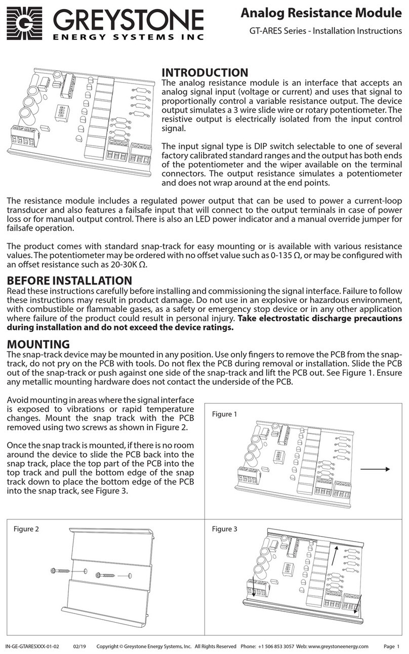
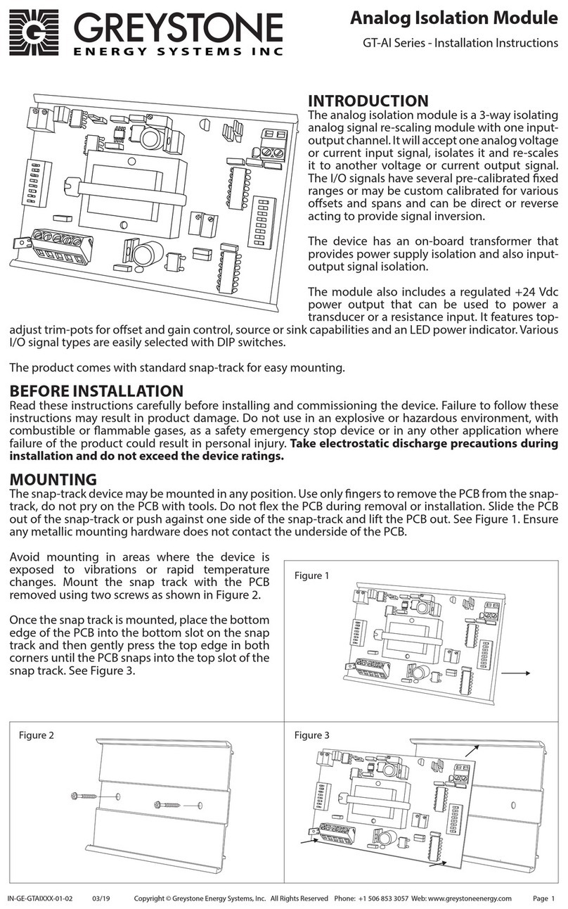
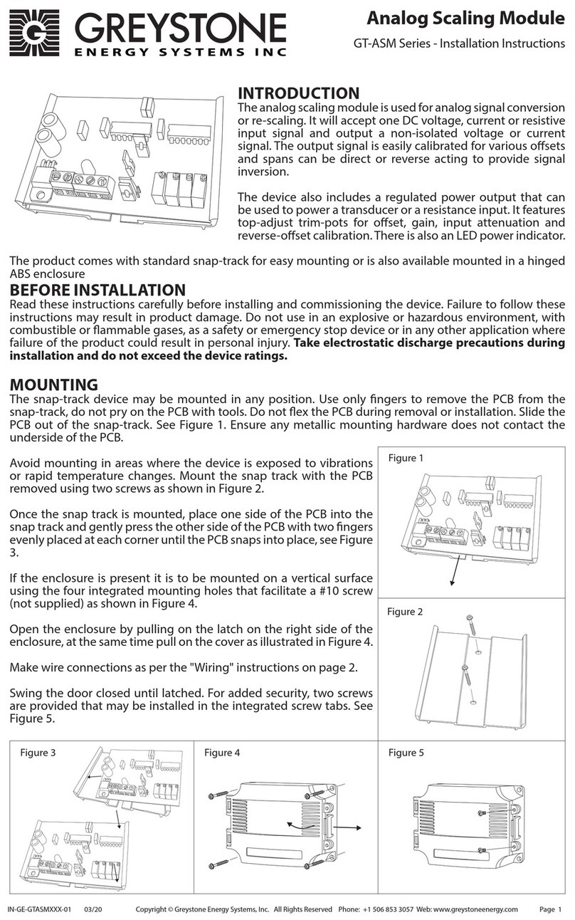
WIRING
• Deactivate any power supplies until all connections are made to the device to prevent electrical shock or equipment damage.
• Follow proper electrostatic discharge handling procedures when installing the device.
• Use 22 AWG shielded wiring for all connections and do not locate the device wires in the same conduit with wiring used to supply inductive
loads such as motors.
• Make all connections in accordance with national and local codes.
• The analog input signal is connected to the IN+ and IN- terminals and the analog output signal is connected to the OUT+ and OUT- terminals.
The input and output signals are completely isolated from each other.
SPECIFICATIONS
GENERAL
Power Supply....................................... Powered by loop-current (15-30 Vdc)
Isolation ................................................. 1000 Vrms input to output
Accuracy ................................................ ±0.1% typical
Operating Conditions ....................... 0 to 50°C (32 to 122°F), 5 to 95 %RH non-condensing
Storage Conditions............................ -30 to 70°C (-22 to 158°F), 5 to 95 %RH non-condensing
Wiring Conditions .............................. Screw terminal block (12 to 24 AWG)
Weight.................................................... 56gm (1.98 oz)
Enclosure............................................... Snap track mounting, 61mm L x 83mm W (2.4" x 3.25")
Country of Origin................................ Canada
INPUT SIGNAL
Input Voltage Ranges........................ 0-5, 0-10, 1-5, and 2-10 Vdc
Input Voltage Impedance................ >10 KΩ
Current Signal Type............................ Sink (external transducer generates 4-20 mA)
Input Current Ranges........................ 0-20 and 40-20 mA
Input Current Impedance................ 250 Ω
OUTPUT SIGNAL
Output Current Range...................... 4-20 mA
Output Current Impedance............ 750 Ω max with 24 Vdc supply
Current Signal Type............................ Sink (requires a loop power supply)
Study the wiring diagrams for proper connections with various input/output signal types and
with both sinking or sourcing applications.
FACTORY CONFIGURATIONS
The Isolation Module is preset for 4-20 mA input / 4-20 mA output. The input signal may be
changed by using the DIP switches as shown in Figure 5.
CALIBRATION
The isolator is factory calibrated to ±0.1% accuracy on the 0-5 vdc input type. Using any other
range will result in a transfer accuracy or <±1%. If a higher accuracy signal is required simply
apply the full-scale input signal and adjust the output signal to 20.00 mA using the calibration
pot.
Calibration pot
DIMENSIONS
61mm
2.4"
83mm
3.25"
Figure 4
+24 Vdc
Input
OUT+
OUT -
4-20 mA Receiver
Out
Power
IN+
IN -
4-20 mA Transmitter
Power Supply
+24 Vdc
Common
Out
Common
IN +
IN -
0-10 Vdc Transmitter
Input Signal Type S1 S2 S3
0-5Vdc OFF OFF OFF
0-10 Vdc OFF ON OFF
1-5 Vdc OFF OFF ON
2-10 Vdc OFF ON ON
0-20 mA ON OFF OFF
4-20 mA ON OFF ON
S1
S2
S3
INPUT TYPE
0-5 Vdc Shown
Figure 5
IN-GE-GTAI420XXX-01-02 02/19 Copyright © Greystone Energy Systems, Inc. All Rights Reserved Phone: +1 506 853 3057 Web: www.greystoneenergy.com


