Automation Devices 6006 Series Setup guide

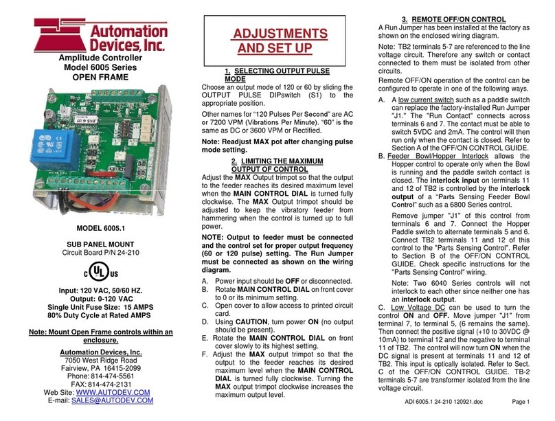
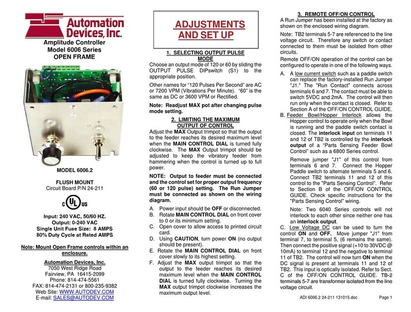
MODEL 6006.1
FLUSH MOUNT
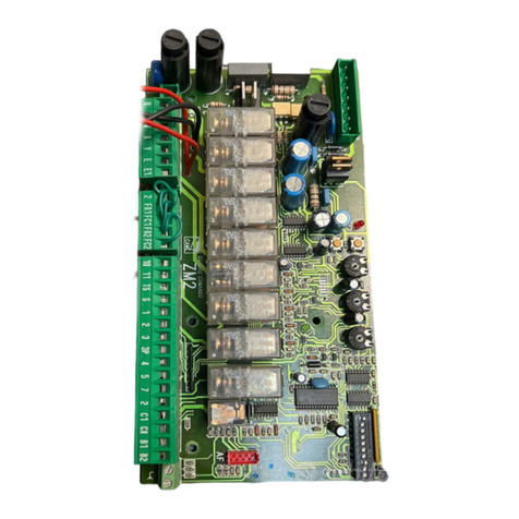
Circuit Board P/N 24-210
Input: 120 VAC, 50/60 HZ.
Output: 0-120 VAC
Single Unit Fuse Size: 15 AMPS
80% Duty Cycle at Rated AMPS
Note: Mount Open Frame controls within an
enclosure.
Automation Devices, Inc.
7050 West Ridge Road
Fairview, PA 16415-2099
Phone: 814-474-5561
FAX: 814-474-2131 or 800-235-9382
Web Site: WWW.AUTODEV.COM
E-mail: [email protected]
1. SELECTING OUTPUT PULSE
MODE
Choose an output mode of 120 or60 by sliding the
OUTPUT PULSE DIPswitch (S1) to the
appropriate position.
Other names for “120 Pulses Per Second” are AC
or 7200 VPM (Vibrations Per Minute). “60” is the
same as DC or 3600 VPM or Rectified.
Note: Readjust MAX pot after changing pulse
mode setting.
2. LIMITING THE MAXIMUM
OUTPUT OF CONTROL
Adjust the MAX Output trimpot so that the output
to the feeder reaches its desired maximum level
when the MAIN CONTROL DIAL is turned fully
clockwise. The MAX Output trimpot should be
adjusted to keep the vibratory feeder from
hammering when the control is turned up to full
power.
NOTE: Output to feeder must be connected
and the control set for proper output frequency
(60 or 120 pulse) setting. The Run Jumper
must be connected as shown on the wiring
diagram.
A. Power input should be OFF or disconnected.
B. Rotate MAIN CONTROL DIAL on front cover
to 0 or its minimum setting.
C. Open cover to allow access to printed circuit
card.
D. Using CAUTION, turn power ON (no output
should be present).
E. Rotate the MAIN CONTROL DIAL on front
cover slowly to its highest setting.
F. Adjust the MAX output trimpot so that the
output to the feeder reaches its desired
maximum level when the MAIN CONTROL
DIAL is turned fully clockwise. Turning the
MAX output trimpot clockwise increases the
maximum output level.
3. REMOTE OFF/ON CONTROL
A Run Jumper has been installed at the factory as
shown on the enclosed wiring diagram.
Note: TB2 terminals 5-7 are referenced to the line
voltage circuit. Therefore any switch or contact
connected to them must be isolated from other
circuits.
Remote OFF/ON operation of the control can be
configured to operate in one of the following ways.
A. A low current switch such as a paddle switch
can replace the factory-installed Run Jumper
"J1." The "Run Contact" connects across
terminals6and7.Thecontactmustbeableto
switch 5VDC and 2mA. The control will then
run only when the contact is closed. Refer to
Section A of the OFF/ON CONTROL GUIDE.
B. Feeder Bowl/Hopper Interlock allows the
Hopper control to operate only when the Bowl
is running and the paddle switch contact is
closed. The interlock input on terminals 11
and 12 of TB2 is controlled by the interlock
output of a “Parts Sensing Feeder Bowl
Control” such as a 6800 Series control.
Remove jumper "J1" of this control from
terminals 6 and 7. Connect the Hopper
Paddle switch to alternate terminals 5 and 6.
Connect TB2 terminals 11 and 12 of this
control to the "Parts Sensing Control". Refer
to Section B of the OFF/ON CONTROL
GUIDE. Check specific instructions for the
"Parts Sensing Control" wiring.
Note: Two 6040 Series controls will not
interlock to each other since neither one has
an interlock output.
C. Low Voltage DC can be used to turn the
control ON and OFF. Move jumper "J1" from
terminal 7, to terminal 5, (6 remains the same).
Thenconnectthepositivesignal(+10 to 30VDC @
10mA) to terminal 12 and the negative to terminal
11 of TB2. The control will now turn ON when the
DC signal is present at terminals 11 and 12 of
TB2. This input is optically isolated. Refer to Sect.
C of the OFF/ON CONTROL GUIDE. TB-2
terminals 5-7 are transformer isolated from the line
voltage circuit.
ADI 6006.1 24-210 131015.doc Page 1
Amplitude Controller
Model 6006 Series
OPEN FRAME
SADJUSTMENTS
AND SET UP
ET UP

4. SETTING THE MINIMUM
OUTPUT LEVEL OF CONTROL
When the vibratory feeder is nearly empty, turn the
MAIN CONTROL DIAL to “1” and adjust the MIN
trimpottojustbelowtheslowestspeedthatprovides
the proper feed rate. The MIN trimpot also serves as
the “low speed” trimpot for 2-speed operation. See
“S1ProgrammingChart”forfeature selection details.
5. MAIN CONTROL DIAL
The output power is controlled by the MAIN
CONTROL DIAL. It is a logarithmic-tapered power
outcurve(non-linear)thatspreadsthe powerbroadly
across the MAIN CONTROL DIAL The logarithmic
taper power curve helps to give maximum "Fine
Control" over the output speed of the vibratory
feeder. When very precise adjustment of the MAIN
CONTROL DIAL is needed, increase the MIN
trimpot setting and/or decrease the MAX trimpot
setting. For precise scaling at low amplitudes, use
the linear POT taper or reduce the Max pot setting.
To select a linear pot taper for the Main Control Dial,
see the “S1 Programming Chart.”
6. SETTING THE SOFT-START
The start-up rate of the control output can be
adjusted to ramp up to the desired output level
instead of starting abruptly. Soft-start keeps parts
from falling off the tooling, reducesspring shock, and
hammering when the control turns ON. Turn the
SOFT Start trimpot clockwise for the gentlest start
(about a 6 sec. ramp up to full output). Turn the
trimpot fully counter-clockwise for no soft start.
7. LINE VOLTAGE COMPENSATION
Fluctuations in the line voltage can cause a feeder
bowl to vary its feed rate. The line voltage
compensation feature adjusts the control's output to
help compensate for fluctuations in the supply
voltage. If it becomes necessary to disable this
feature,set“DisableLVC”fromtheS1programming
chart
8. REMOTE SPEED CONTROL
Remote control of the power level can be
accomplished by the following methods:
A.4-20mAsignalfromaPLCcanbeusedto remotely
vary the output of the control instead of the Main
Control Dial. The 4-20mA input is automatically in
control whenever a 4-20mA signalisappliedto the
control (terminals TB2-8 & 9). The Main Control
dial setting is ignored whenever there is a 4-
20mA signal. The 4-20mA input is transformer
isolated from the power line. In an environment
with high electrical noise, use a shielded cable
for the 4-20mA signal. The “S1 Programming
Chart” shows how change to 0-20mA speed
control instead of the default of 4-20mA.
B. A 0-5VDC Analog input signal may be applied
in place of the Main Control Dial at H1. The 0-
5VDC input is transformer isolated from the power
line. 9. SUPPLEMENTARY FEATURES
Special supplementary software features can be
enabled on the 24-210/24-211 circuit boards The
features include: linear pot taper, 0-20mA control,
empty bowl timer, low pulse rates, and two speed
pots. See the S1 Switch Programming Chart.
Contact the manufacturer for more information.
10. STATUS LEDs
When any of the inputs are active, the associated
LED will turn ON. When the RUN input conditions
are met, the RUN LED will turn ON. See section 3
and the wiring diagram’s ON/OFF Control Guide
for more information on how to satisfy the RUN
conditions.
WARNING:
Fuses should be replaced with a Bussman
ABC or Littelfuse 3AB "Fast Acting" type or
equivalent of manufacturer's original value.
Mounting this control directly to a vibrating
device will void the warranty.
TROUBLESHOOTING
Basic Procedure – To ascertain whether the
problem lies in the controller, take the following
steps:
A. Check for good fuses. Disconnect the input
power and tighten the screw terminals.
B. Forthecontroloutputtobeon:Makesurethat
the proper input power is present. The MAIN
CONTROL DIAL must be turned up or if the
4-20mA input is used, it must have over 5mA.
Either the DIRECT LED must be lit or both
theINTERLOCKandEXT VOLTS LEDs must
be lit. Anytime the output is turned on, the
RUN LED will be ON. To light the DIRECT
LED, a Run Jumper must be connected at
TB2-6 & TB2-7. To light the INTERLOCK
LED, a Run Jumper must connect TB2-5 to
TB2-6. To illuminate the EXT VOLTS LED, a
10-30VDCsignalhastobe presentatTB2-11
&12. Seethesectiontitled“Remote OFF/ON
control” for more information.
C. Connect an AC voltmeter across the LOAD
terminals (withtheLOADconnected)and vary
the MAIN CONTROL DIAL from minimum to
maximum. In 120 pulse mode, the output
should vary from approximately 30% to 98%
of the input voltage depending on the setting
of the MIN and MAX trimpots. In 60 pulse
mode the output should vary from 20% to
around 85% of the input voltage.
D. On new installations: If the Feeder only hums
but it doesn’t feed any parts, try changing the
60/120 DIP switch (S1) to the opposite
position.
When neither a humming sound nor any vibration
can be detected in the vibratory feeder, the
problem may be in the controller.
ADI 6006.1 24-210 131015.doc Page 2
S1 Programming Chart
Program Description S1 Switch Positions
SW3 SW4 SW5
Standard Program 0 0 0
Linear Pot Taper 1 0 0
0-20mA option 0 1 0
Empty Bowl Timer 1 1 0
Disable LVC 0 0 1
2-Speed Operation 1 0 1
30/40 Pulse Operation 0 1 1
Low Voltage at “1” 1 1 1

TERM STRIP TB-2, OUTPUT
-
RD
+
8
910
(DC Voltage from PLC)
10
10-30 VDC INPUT VOLTAGE
8
PADDLE
LOW VOLTAGE INPUT SWITCHING
OFF/ON CONTROL
+
-7
C)
6
6
6000 SERIES TERM STRIP TB-2
11
8
10
B)
7
5
5
12
SWITCH
6
7
See section 3 of the Application Note for more
details.
5
6800 SERIES
9
9
6000 SERIES TERM STRIP TB-2
1112
12
6000 SERIES TERM STRIP TB-2, INPUT
11
LOW CURRENT
SWITCH
A)
OR
J1
FEEDER BOWL/HOPPER INTERLOC
K
OFF/ON CONTROL GUIDE
P/N 24-210/24-211
OUTPUT POWER
Or #14
GND
INPUT POWER
COM COM
HOT
Wh #14
Vi #20
GND
HOT
CHASSIS
Soft
TRANSFORMER
Bl #14
POWER
Sig.
1
Bl #14
Wh #14
-
SIG
100K
+cw
Bl #14
CONTROL
1/8WMIN
POT
MAIN
Min Max
11
8
6
8
12
60
SW5
External
SW3
SW4
-
JUMPER
+
2
59 7
1110
4
12
7
6
3 5
1
10
9
LINE VOLTAGE
LOAD
TERM. STRIP
G
P/N 24-210
(SMALL)
+
AC HOT
AUX FEATURE
Pot Input
AC COMMON
120
TB2
TB2
TERM. STRIP
4-20mA
J1
(TALL)
TB1
+
-
-
S1
RUN
TB1
Direct
RUN
Interlock
H1
INTERLOCK
INPUT
60 Rev
GATE
A2 TRIAC
A1
Bl #14
Automation Devices, Inc.
Automation Devices, Inc.
7050 West Ridge Road
Fairview, PA 16415-2099
Phone: 814-474-5561
FAX: 814-474-2131 or 800-235-9382
Web Site: WWW.AUTODEV.COM
E-mail: [email protected]
DIMENSIONS
MODEL 6006.1
OPEN FRAME MODEL
INSTRUCTIONS
MODEL INPUT VAC AMPS OUTPUT
6006.1 120VAC 15A 0-120
ADI 6006.1 24-210 131015.doc Page 3
Customer supplied wiring
is shown by dashed lines
This manual suits for next models
1
Other Automation Devices Controllers manuals
Popular Controllers manuals by other brands
LAE electronic
LAE electronic CDC122T1R2 Instructions for installation and use
Mitsubishi Programmable Controllers
Mitsubishi Programmable Controllers ENHANCED F2 Series instruction manual
THERMATEC
THERMATEC TH-Ti800 Installation and user manual
Trio Motion
Trio Motion PC-MCAT 64 quick start guide
Rockwell Automation
Rockwell Automation Allen-Bradley Logix 5000 Series Programming manual
Siemens
Siemens Simatic S7-1500 manual
