3. DISPLAYS
3.1 D
URING ORDINARY
C
ONTROL
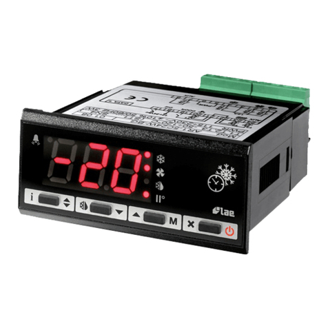
.At the power up, the display shows "---" for 5 seconds during which the unit carries out a self-check; then the
temperature T3 appears. In some cases, owing to the structure of the cabinet or air stratification, the probes can not measure the desired temperature.
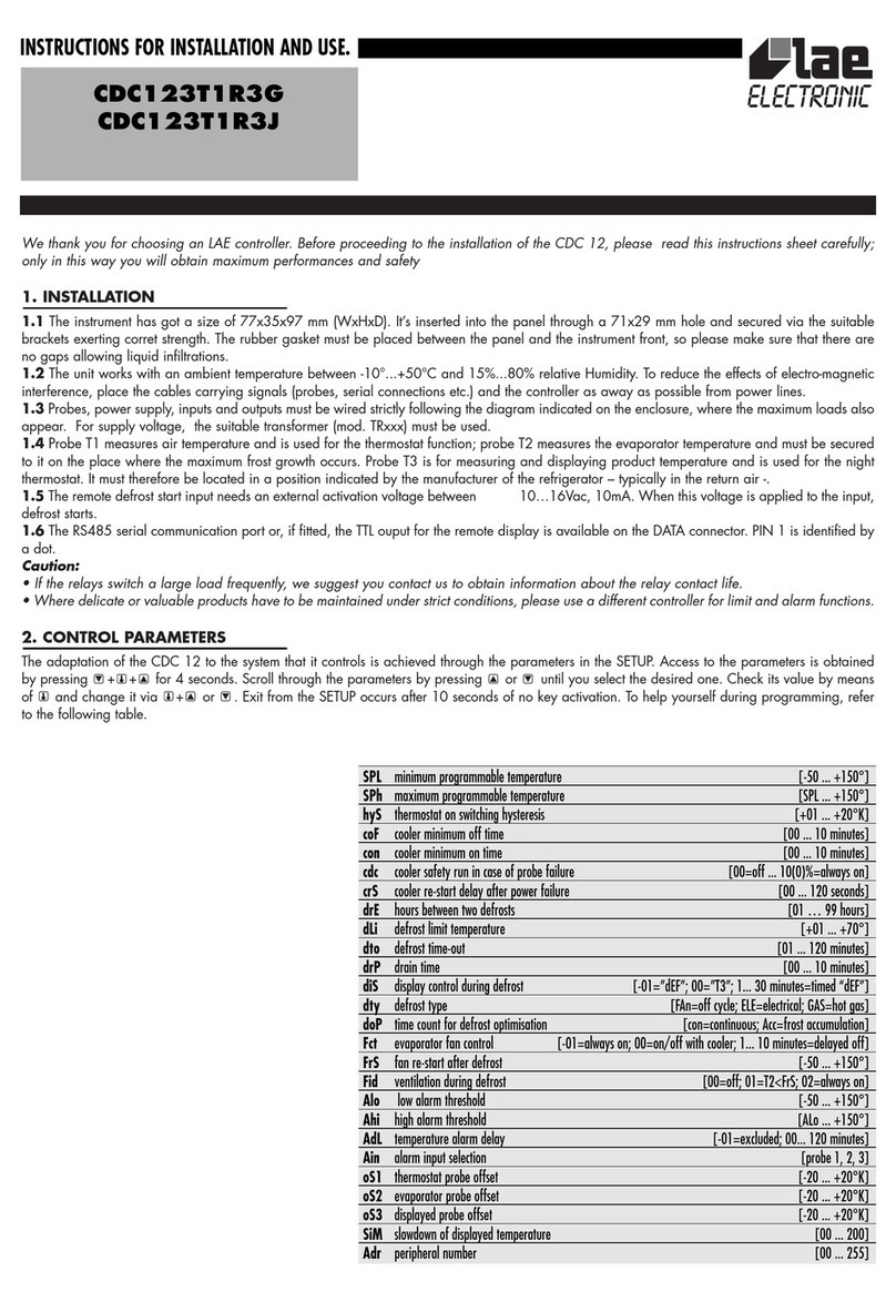
If necessary, through the parameters oS1, oS2 and oS3 the temperatures t1,and t2 measured by the probes can be adjusted in order to obtain the
desired values for computing: thermostat T1=t1+oS1; defrost T2=t2+oS2; display T3=t1+oS3.
Ex.: Setpoint= -20°; oS1= -2°K; oS3= +6°K, temperature t1 is controlled at -18° and the display shows -12°.
Through the SiM parameter it’s possible to reduce the fluctuations of the displayed temperature by simulating the behaviour of product core
temperature. The slowdown is proportionated to the value programmed to SiM (ex.: 100 simulates approx. a 0.5 l bottle of water). To display the
instantaneous temperatures T1, T2 or T3 press , or respectively.
3.2 D
URING DEFROST
.The display is controlled according to the parameter diS, if 00 temperature T3 continues to be displayed. If diS= -01, then
the display shows "dEF" since defrost start as long as the temperature T1 is higher than setpoint+hysteresis hYS. By programming a value between
1and 30 minutes, after the defrost "dEF" is still displayed until the time programmed has elapsed unless the above condition is reached before.
3.3 O
THER
D
ISPLAY
S
TATUS
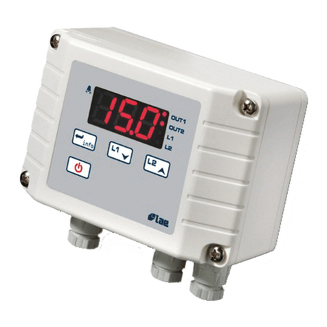
.During an alarm condition, “ALM” blinks on display. The stand-by status, in which all outputs are off, is signalled with
permanent "---". If the keypad has been locked through the serial communication, when attempting to perform any changes, the display shows “inh”.
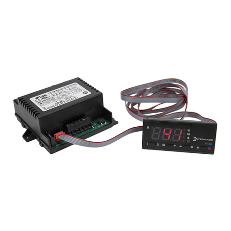
The optional remote display (CDCREMOTO) repeats the indications of the CDC12 to which it’s connected, except during the alarms which are
indicated with “---“. When a fault in communication occurs, the remote unit shows “..-..” (only the line in the centre).
4. THERMOSTAT FUNCTION
At power-up the cooler start is delayed by the sum of coF and crS; this latter is used in those applications where it is necessary, after a line dropout,
to avoid simultaneous starts of many compressors at the power-up. For ex.: coF= 03, crS= 05; after power-up, at least 03 minutes and 05 seconds
must elapse before the cooler starts. coF and con are, respectively, the cooler minimum off and on time. The relay which controls the cooler, after
switching off/on or on/off, will remain in that status for at least the pre-programmed time. When you have to maintain a very small hysteresis hyS,
we recommend to program a suitable value for coF and con to ensure a long life to relay/contactor and compressor.
Temperature control is based on the comparison between temperature T1, the setpoint and the hysteresis hyS programmed. The setpoint is displayed
by pressing . To change it, keep pressed and by pushing key or , select the desired value within the limits SPL and SPh. The cooler on
switching temperature is achieved by adding hyS to the setpoint.
Ex.: setpoint=-03; hyS=04, the relay is off with T1=-03°C and on with T1=+01°C.
When a failure or overrange of probe T1 occurs, the cooler run isn't controlled according to setpoint but determined by cdc which represents the
cooler duty cycle, i.e. (on time)/(10 minute cycle). For ex.: 04= 4 minutes on time, 6 minutes off time. The cdc value has to be set taking into
consideration the normal cooler duty cycle.
If you wish to switch off the outputs, you can put the CDC12 on a standby via the serial communication or manually, by pressing + + during
self-check following the power-up. During the standby temperature control and serial communication however remain active. If the CDC12 is on a
standby, you can get it to go out of this status and resume its ordinary operation by following the same procedure as described above.
5. DEFROST START
5.1 T
IME
C
OUNT
.If doP=con, then the time count is continuous, therefore defrosts take place at regular intervals in hours set with parameter drE.
If doP=Acc, then the built-in timer only counts when a frost growth condition occurs (i.e. fin temperature lower than 0° and below the dew point) until
reaching the drE time. If the evaporator works at around 0°, defrost frequency depends on the thermal load and the climatic condition (external air
temperature and humidity). If setpoint is much lower than 0°, then defrost frequency mainly depends on the cooler on times. Ex. If the cooler cycle is
5 minutes on and 5 minutes off and drE= 04 hours, defrost takes place every 8 hours approximately.
After a power failure, the defrost timer resumes the time count from where it was interrupted with ±30 minute approximation.
5.2 R
EMOTE
S
TART
.It allows to start a defrost remotely regardless of the time elapsed. This function permits to perform defrosts not homogeneously
spread in time or according to a program. The activation of the remote start anticipates a defrost, of which start is however determined by drE.
Ex. If drE=12 and within 12 hours since the last defrost no start signal is sent to the CDC12, then defrost will however take place. This function overlap
avoids that a fault in the remote control or in the connection excludes any defrost.
5.3 M
ANUAL
D
EFROST
.It is possible to manually start or abort defrost by pushing + .
6. DEFROST FUNCTION
6.1 E
VAPORATOR
H
EATING
.During defrost the status of the outputs is determined by parameter dtY. If dtY=FAn, then the evaporator fans are kept
on, while cooler and defrost outputs are off. If dtY=ELE, during defrost the cooler is switched off and the defrost output on. If dtY=GAS, cooler and
defrost outputs are on all through defrost.
6.2 T
ERMINATION
.When defrost is on, it can be terminated in different ways: if defrost time-out dto is greater than 0, it gives the maximum defrost
duration in the event that temperature T2 doesn’t match the dLi value before. If dto=0, then defrost ends when either temperature dLi is achieved or
when the remote contact is opened.
Warning: if you don’t use the remote defrost start input and you program dto=0, then defrost will be aborted immediately after its start!
6.3 D
RIPPING
.After the heating phase, the dripping time drP, by delaying the cooler re-start, allows a homogeneous heat spread all over the
evaporator and the drain of the drops of water.
The defrost LED is lit when the corresponding output is On; it blinks during defrost through "air blowing" and dripping time.
INSTRUCTIONS FOR INSTALLATION AND USE.
