Automation Technology C5-2040CS18-38-2X User manual

C5-2040CS18-38-2X
User Manual
for High Speed Laser 3D Sensors
Rev. 1.1
AT - Automation Technology GmbH

Copyright
© 2018 Automation Technology GmbH
All rights reserved. No part of this document shall be reproduced, stored in a retrieval
system, or transmitted by any means, electronic, mechanical, photocopying, recording,
or otherwise without consent in writing from the owners, AT-Automation Technology
GmbH.
Disclaimer
While care has been exercised in the preparation of this document to ensure that it is fully
correct and comprehensive, the owners assume no responsibility for errors or omissions.
Neither is any liability assumed for damages resulting from the use of the information
contained herein. No license is granted under any patents or patent right of AT –
Automation Technology GmbH.
Trademarks
All nationally and internationally recognized trademarks and trade names are hereby
acknowledged.
This document is subject to change without notification. All rights reserved.

C5-2040CS18-38-2X Manual Rev. 1.1
1
Table of Contents
TABLE OF CONTENTS ........................................................................................................................1
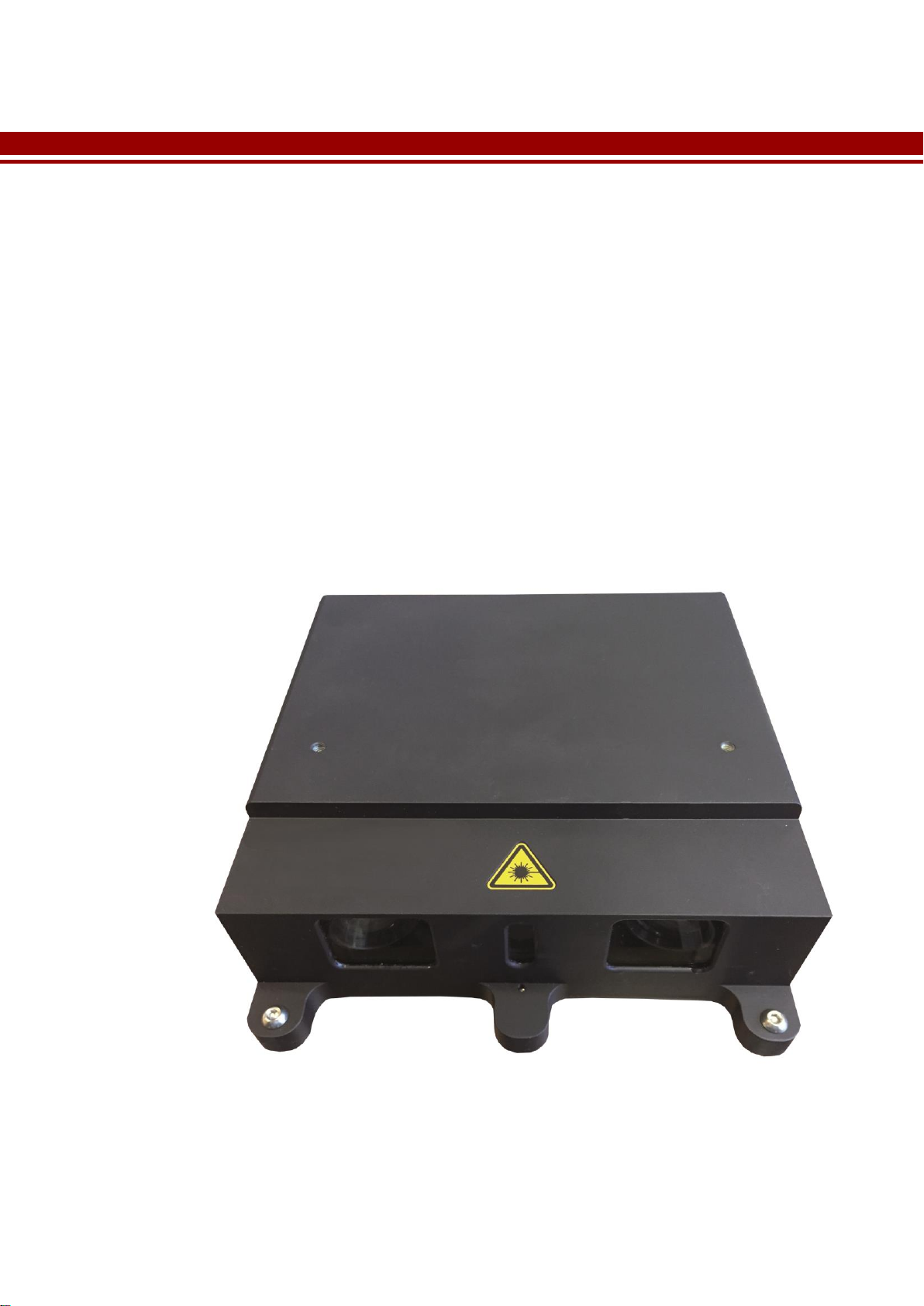
C5-2040CS18-38-2X OVERVIEW........................................................................................................2
Introduction............................................................................................................................................................2
C5-2040CS18-38-2X General Specifications .............................................................................................................3
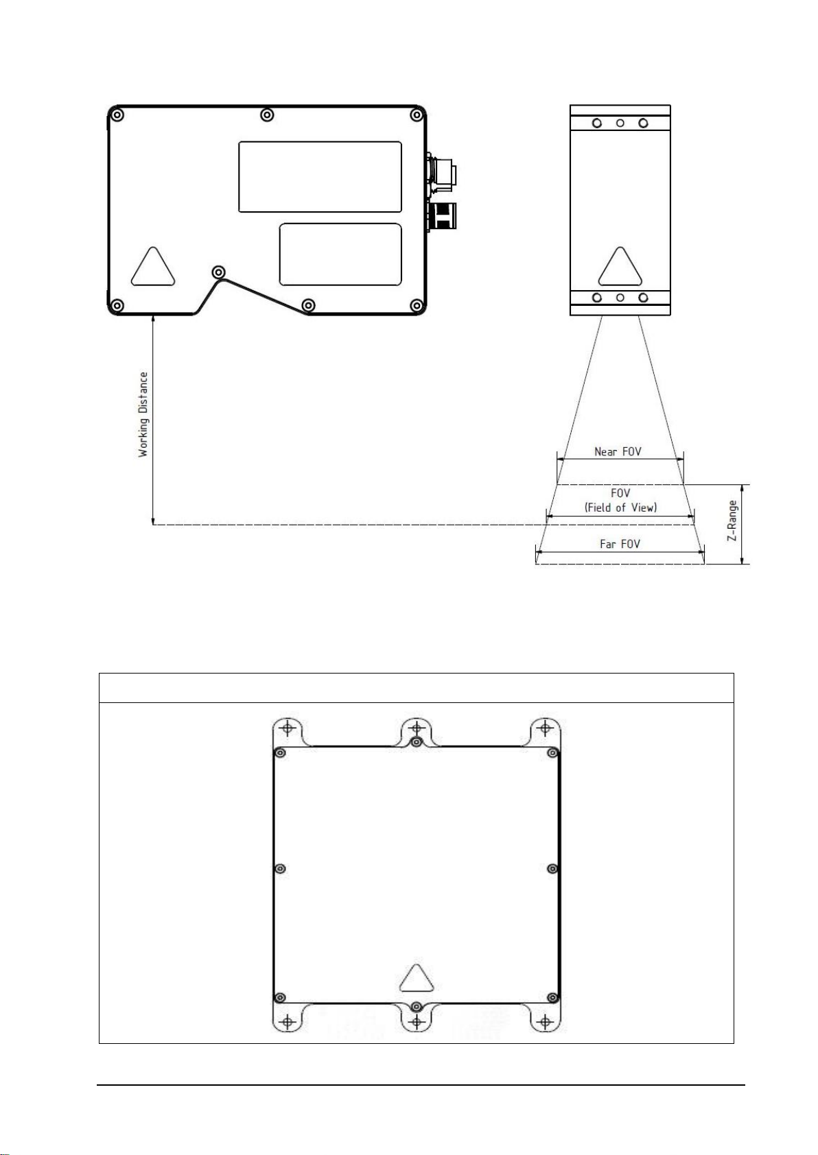
Model Overview with Measurement Specification................................................................................................... 5
Mechanical Drawing.................................................................................................................................................. 6
Housing Type ........................................................................................................................................................ 6
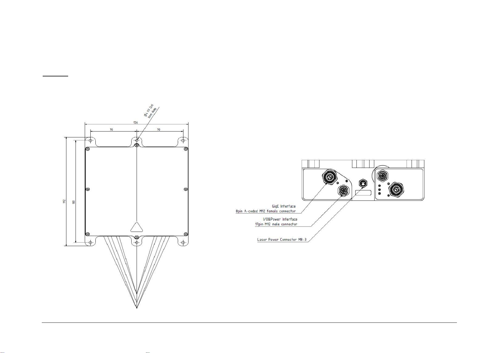
Dimensions ........................................................................................................................................................... 7
Wire assignment for Laser ........................................................................................................................................ 9
Description of LEDs ................................................................................................................................................. 10
Master................................................................................................................................................................. 10
Slave.................................................................................................................................................................... 11
SERVICE INFORMATION ..................................................................................................................12
Product Information and Updates ........................................................................................................................12
Warranty Conditions.............................................................................................................................................13
Warranty Period...................................................................................................................................................... 13
Extended Warranty ................................................................................................................................................. 13
Return Policy ........................................................................................................................................................13
Document Revision...............................................................................................................................................14

C5-2040CS18-38-2X Manual Rev. 1.1
2
C5-2040CS18-38-2X Overview
Introduction
The C5-2040CS18-38-2X sensor is a revolutionary product of an intelligent high speed laser
triangulation sensor of the C5-CS family. It is optimised for 3D profile measurement by
means of laser triangulation technique. The 3D profile extraction is performed in the sensor
by using high performance Field Programmable Gate Array processors. At the same time
the 3D profile data is sent to the PC over a Gigabit Ethernet interface (GigE). This extreme
data reduction boosts the measuring speed to unprecedented levels without affecting
the performance of the connected image processing unit.

C5-2040CS18-38-2X Manual Rev. 1.1
3
C5-2040CS18-38-2X General Specifications
Sensor Controls
Synchronization Modes
Free Running, Triggered, Software Triggered
Exposure Modes
Programmable, Pulse Controlled
Shutter Modes
Global Shutter
Digital Input
2 electrical isolated inputs, +5V…+24V DC
VIL, logic “0”Voltage < 1.5V
VIH, logic “1” Voltage > 3.5V
Max. frequency: 450 kHz
Digital Output
2 electrical isolated outputs, +5V…+24V DC
VOL, logic “0” Voltage < 0.5V
VOH, logic “1” Voltage ≥ 3.8V
IOH, logic “1” drive current max. 100 mA
IOL, logic “0” drive current max. 100 mA
Encoder/Resolver Input
A+,A-, B+,B-, Z+, Z-
High-Speed Triple RS-422 Receiver
Max. input voltage +5V DC (TTL signal)
RS-422-Mode, max. frequency: 15 MHz
Laser Supply
Reverse voltage protection
Supply voltage +5V…+24V DC
Laser modulation
Sensor Features
High Dynamic Range Imaging
Multiple Slope, Multi-Frame Readout
3D-Algorithms
MAX, TRSH, COG, FIR PEAK
3D-Scan Features
Automatic AOI-Tracking, Automatic AOI-Search,
Multiple AOIs, AutoStart
Electrical Interface
Power Supply
+10V…+24V DC (max. +27V DC)
Power Consumption
6W
Operating Temperature
0 °C to +50 °C (non-condensing)
Output Data Interface
Gigabit Ethernet (IEEE 802.3)
Communication Protocol
GigE Vision with GenICam
Mechanical Interface
Power Connector
17 pin, M12 connector
Ethernet Connector
8 pin, A-coded M12 connector

C5-2040CS18-38-2X Manual Rev. 1.1
4
Mechanical Stress Specification
Vibration (sinusoidal each axis)
2 G, 20…500Hz
IEC 60068-2-6
Shock (each axis)
15 G
IEC 60068-2-27
Enclosure rating
IP67
IEC 600529

C5-2040CS18-38-2X Manual Rev. 1.1
5
Model Overview with Measurement Specification
Model Name
Nominal
FOV
FOV Near
Field
FOV Far
Field
Z-Range
Working
Distance
Lateral
Resolution
Height
Resolution
Points per
Profile
Housing
Type
[ mm ]
[ µm ]
[ pixels ]
C5-2040CS18-38-2X
38
37
40
30
117
19
0.8
2048
Model 5

C5-2040CS18-38-2X Manual Rev. 1.1
6
Mechanical Drawing
Housing Type
Model 5

C5-2040CS18-38-2X Manual Rev. 1.1
7
Dimensions
Model 5
All dimensions in mm

C5-2040CS18-38-2X Manual Rev. 1.1
8
All dimensions in mm

C5-2040CS18-38-2X Manual Rev. 1.1
9
Wire assignment for Laser
M8 Laser Male Connector Pin Assignment
Pin No.
Signal Name
Description
1
24V (<15W)
24V Power Supply
3
N.C.
-
4
GND
Power Supply Ground
Cable Pin Assignment
Pin/Wire No.
Wire Colour
Signal Name
Description
1
Brown
Vcc_Laser
24V Power Supply
2
Black
GND
Laser Supply Ground
3
Blue
-
n.c.

C5-2040CS18-38-2X Manual Rev. 1.1
10
Description of LEDs
Master
LED
Description
1 (USR)
After Power On:
Off = No network cable connected
Green On = Network connected
After Network connected:
Green On = CCP status connected
Off = CCP status disconnected
2 (LSR)
Red On = Laser is On
Off = Laser is Off
1
2

C5-2040CS18-38-2X Manual Rev. 1.1
11
Slave
LED
Description
1 (LSR)
No function
2 (USR)
After Power On:
Off = No network cable connected
Green On = Network connected
After Network connected:
Green On = CCP status connected
Off = CCP status disconnected
Red On = No network found, no network cable connected
3 (PWR)
Green On = Power On and camera start up completed
Off = Power Off or camera start up failed
4 (LNK)
Green On = Linkspeed 1 Gbit
Amber On = Linkspeed 100 Mbit
Off = Linkspeed 10 Mbit or wait for end of auto negotiation
5 (ACT)
Green blink = Indication of network activity
1
2
3
4
5

C5-2040CS18-38-2X Manual Rev. 1.1
12
Service Information
Product Information and Updates
Contact
AT-Automation Technology GmbH
Hermann-Bössow-Str. 6-8
D-23843 Bad Oldesloe, Germany
Phone: +49 4531/88011-0
Fax: +49 4531/88011-20
Updates
www.AutomationTechnology.de
Service and Support
service@AutomationTechnology.de
In order to process your support inquiries immediately, we always need the serial number
of the camera, the firmware version, the device version, the camera configuration file
(*.cfg), a snapshot and a precise problem description.
Product Inquiries and Price Quotations
info@AutomationTechnology.de

C5-2040CS18-38-2X Manual Rev. 1.1
13
Warranty Conditions
Only the manufacturer can recognize the conditions of warranty. Should other parties
than the manufacturer be responsible for the malfunctioning, we consider the right of
warranty as void. This is the case if the unit is modified electrically or mechanically,
particularly in its wiring/soldering, or if the unit is used for purposes not intended by the
manufacturer, or if the unit's external wiring is faulty, or if the unit is used under conditions
outside those stated in its manual.
Warranty Period
The sensors warranty for the C5-CS series is 1-year starting from the date of purchase from
AT –Automation Technology GmbH.
Extended Warranty
The warranty period can be extend to maximum 36 months.
Return Policy
Before returning a sensor for repair (warranty or non-warranty) to AT –Automation
Technology GmbH a Return Material Authorization (RMA) number have provided by AT.
Please get in contact with AT to receive a RMA.
Ship the sensor carefully packed in its original shipping box or an equivalent box back to
our destination in Germany, 23843 Bad Oldesloe, Hermann-Bössow-Straße 6-8.
If you purchased a camera over a distributor, please get in contact with them to start the
RMA process.

C5-2040CS18-38-2X Manual Rev. 1.1
14
Document Revision
Rev. No.
Date
Modification
1.0
18.04.2017
First Draft
1.1
07.09.2018
Minor Corrections
Table of contents
Popular Industrial Equipment manuals by other brands

CopperSmith
CopperSmith CSPI-30 installation instructions

Dorner
Dorner Aquaguard 7350 Series Installation, Maintenance, and Parts Manual

CE CLEVELAND
CE CLEVELAND SGP Series Operation manual

Siemens
Siemens LD-BV-KE-B-WP installation instructions

Mayr
Mayr EAS-NC Installation and operating instructions

Grant Fidelity
Grant Fidelity DAC-09 Modification Instructions