AutomationDirect AcuAmp VADT Series User manual

Part Number Key
AutomationDirect.com (ADC)
3505 Hutchinson Road, Cumming, GA 30040
Phone: (800) 633-0405 or (770) 889-2858
VADT SERIES
INSTALLATION
INSTRUCTIONS
Quick Start Guide
1. Ensure correct sensor model was chosen for
monitored voltage of application.
2. Mount the sensor to a DIN rail using an
integrated mounting clip on the backside of the
transducer.
3. Connect input voltage to be monitored to
terminals 5 & 6 using 30-12AWG copper wires
rated 75/90°C, 5-7 in-lbs torque. Output and
power wiring using 22AWG up to 12AWG copper
wires rated 75/90°C, 6 in-lbs torque..
4. Connect 24VAC or DC power supply fused to 5
amps to terminal 3 & 4.
Do not connect power and signal together.
VADT - 050 - 42 - 24
SENSOR TYPE
VADT AC/DC Voltage
OUTPUT
POWER SUPPLY
MONITORED VOLTAGE RANGE
015 - 15V
050 - 50V
150 - 150
500 - 500
24 - 24 VAC/DC
42 - 4-20mA
®
VADT - Inst - Rev 1 0820 P-N 292180027
Specifications
Power Supply 24 VAC/DC (+/-8.3%) External Power
(Note: Output and power supply negatives are
not isolated.)
Power Consumption < 2VA
Voltage Measurement 15, 50, 150, and 500 VAC or DC
Frequency Range 0 - 5KHz
Output 4 - 20 mA
Output Limit 31mA
Response Time 500 ms (90% step change)
Accuracy <1% Full Scale
Output Impedance < 400Ω
Isolation Voltage UL tested to 2200VAC
Case UL 94V-0 Flammability rated thermoplastic
Environmental
-Temp -4 to 122°F (-20 to 50°C)
-Humidity 0-95% RH, Non-condensing
-Pollution degree 2
-Altitude 2000 meters
Certifications cULus listed E222847
CE
Warning! Risk of electric shock or
personal injury
Safe operation can only be guaranteed if the
device is used for the purpose for which it was
designed and within the limits of the technical
specifications. When this symbol is used, it
means you should consult all documentation to
understand the nature of potential hazards and
the action required to avoid them.
Warning! Risk of hazardous voltage
When operating the device, certain parts may
carry hazardous live voltage (e.g., primary
conductor, secondary terminals). The device
should not be put into service if the installation is
not complete.
For products intended for the EU market, the
following is applicable to the CE compliance of
the product:
The VADT Series comply with EN 61010-1 CAT III 600V max
measurement category. Use 24 V input power and fuse at 5
amps. Power source overvoltage category I as defined per EN
61010-1.
Part No. VADT015-42-24
Troubleshooting
1. Transducer has no output.
A. Power supply is not properly sized.
Check the power supply voltage and output rating. Each
transducer requires less than 2VA to operate.
B. Output polarity is not properly matched.
Check and correct wiring polarity.
2. Output signal too low or too high.
Transducer model improperly sized for application.
Determine the normal operating voltage of your monitored
circuit and ensure transducer selected is equal to or slighly
higher than the normal operating voltage.
3. Transducer output is always at 4mA.
A. Primary circuit is not on.
Check that the monitored circuit is actually energized.
4. Transducer output is always at 20mA.
Voltage is higher than transducer range.
Select a higher range product.
Description
VADT Series Voltage Transducers are designed to monitor AC
or DC voltage and detect conditions where supply voltage
is above or below normal. Detecting such conditions helps
users to avoid problems commonly associated with voltage
irregularities such as motor overheating, brownouts and
conductor failure or poor connections.
Installation
VADT transducers feature a 35mm wide DIN rail-compatible
enclosure and are typically located in the same environment
as motors, contactors, heaters, pull-boxes, and other electrical
enclosures.
To mount on DIN rail: Orient transducer so that line voltage
terminals L1 and L2 are upright/on top of unit and snap
securely onto DIN rail. To remove, insert a small screwdriver
into the lower mounting hole of the spring-loaded clip, and
push the handle end of the screwdriver toward the sensor base
to release the tension on the rail.
Output Wiring
Connect control or monitoring wires to the sensor terminals
1 and 2. Use 22-12 AWG copper wire insulated to 75/90°C
and tighten terminals to , 6 in-lbs torque.
Observe polarity, terminal 1 is the postiive output, 2 is
negative.
To mount using screws: Insert screws and mount to
backplane or other suitably flat surface.
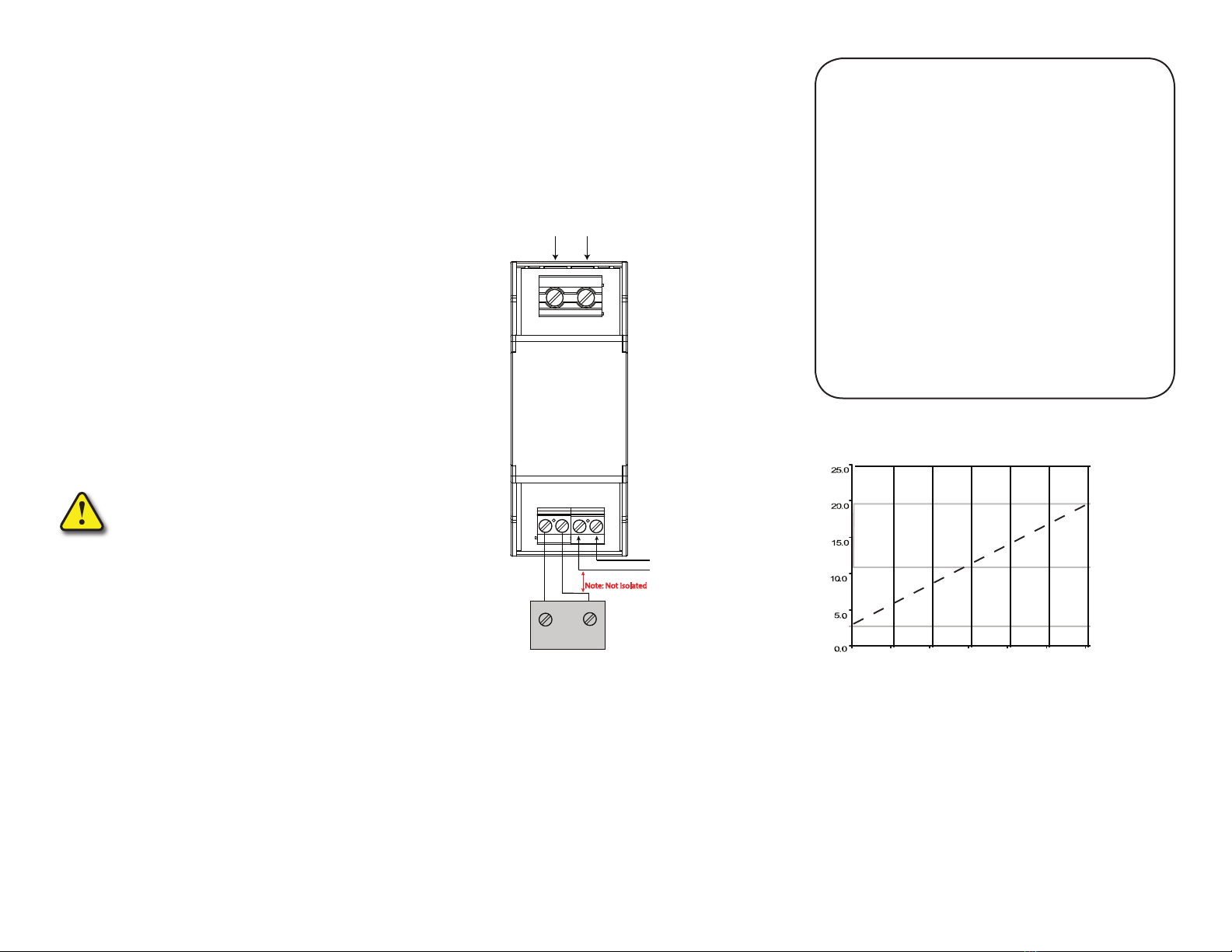
Monitored Voltage Wiring Connection
CAUTION: To avoid any potential for shock
or safety hazard, ensure line voltage is
disconnected at source before wiring to unit.
Connect input voltage to be monitored to terminals (5) and
(6) on transducer using 30-12 AWG copper wires and tighten
terminals 5-7 inch pounds torque.
Do not connect the power supply and signal together.
There is no isolation between power and signal.
(mA)
(% FS)
Transducer Output vs. Input Voltage
0.0 100.0
50.0
Input Voltage
Current Output
VADT Series
+
AC/DC Voltage (primary)
(5) (6)
+-
Load
(PLC, meter,etc.)
24 VAC/DC
Power Supply
(1) (2) (3) (4)
Other AutomationDirect Accessories manuals


