Cerlic O2X Duo User manual

2018-11-20 C14D5EN19
O2X DUO
Dissolved Oxygen
Sensor

O2X
DUO
- 2 -
TABLE OF CONTENTS
Introduction 3
1. A few words about this manual 3
2. Design 3
3. Measuring principle 3
4. Unpacking the sensor 4
Packaging .......................................................................................................... 4
Content .............................................................................................................. 4
Optional parts for O2X DUO: P/N........................................................... 4
5. Mounting the sensor 5
Cable Connections............................................................................................. 5
Installation Tips ................................................................................................. 5
6. Removing the sensor 6
7. Changing or installing a new electrode/cell 6
Removing an old electrode/cell:........................................................................ 6
Installing a new electrode/cell:.......................................................................... 7
Mounting the protection plate ........................................................................... 7
8. Cleaning the Sensor 8
Cleaning the Flushing Nozzle ........................................................................... 9
Mounting plate for solenoid valves ................................................................... 9
9. Sensor display 9
10. Menu for O2X DUO Sensor 10
Settings ............................................................................................................ 10
Calibrate .......................................................................................................... 10
Cleaning........................................................................................................... 11
Scale / Alarm ................................................................................................... 11
System ............................................................................................................. 11
11. Calibration 12
Zero Calibration .............................................................................................. 12
Air calibrating a sensor.................................................................................... 13
Air pressure conversion................................................................................... 14
12. Scaling 14
13. Technical description 15
Certificate of conformity:................................................................................ 15
14. Dimensions 16
Appendix 1, Assembly of handrail mounting kit 16
......................................................................................................................... 16
Appendix 2, Assembly of adjustable slide rail 18
Appendix 3, Support information 19
Appendix 4, Setup information 20
Service form 21

O2X
DUO
- 3 -
Introduction
The O2X DUO sensor is designed to continuously measure dissolved oxygen levels in
liquids. The O2X DUO is effective in saving energy costs associated with aeration
systems in an activated sludge process. In addition, accurate measuring of dissolved
oxygen allows for better control of nitrification/denitrification.
The O2X DUO features two different principles of measuring; Clark Cell electrode or
optical cell. See section 3 below.
1.
A few words about this manual
This manual details installation procedures and operational features of the Cerlic O2X
DUO sensor. Menu navigation and technical data for the BB1/BB2 control box can be
found in the BB1/BB2 service manual.
2.
Design
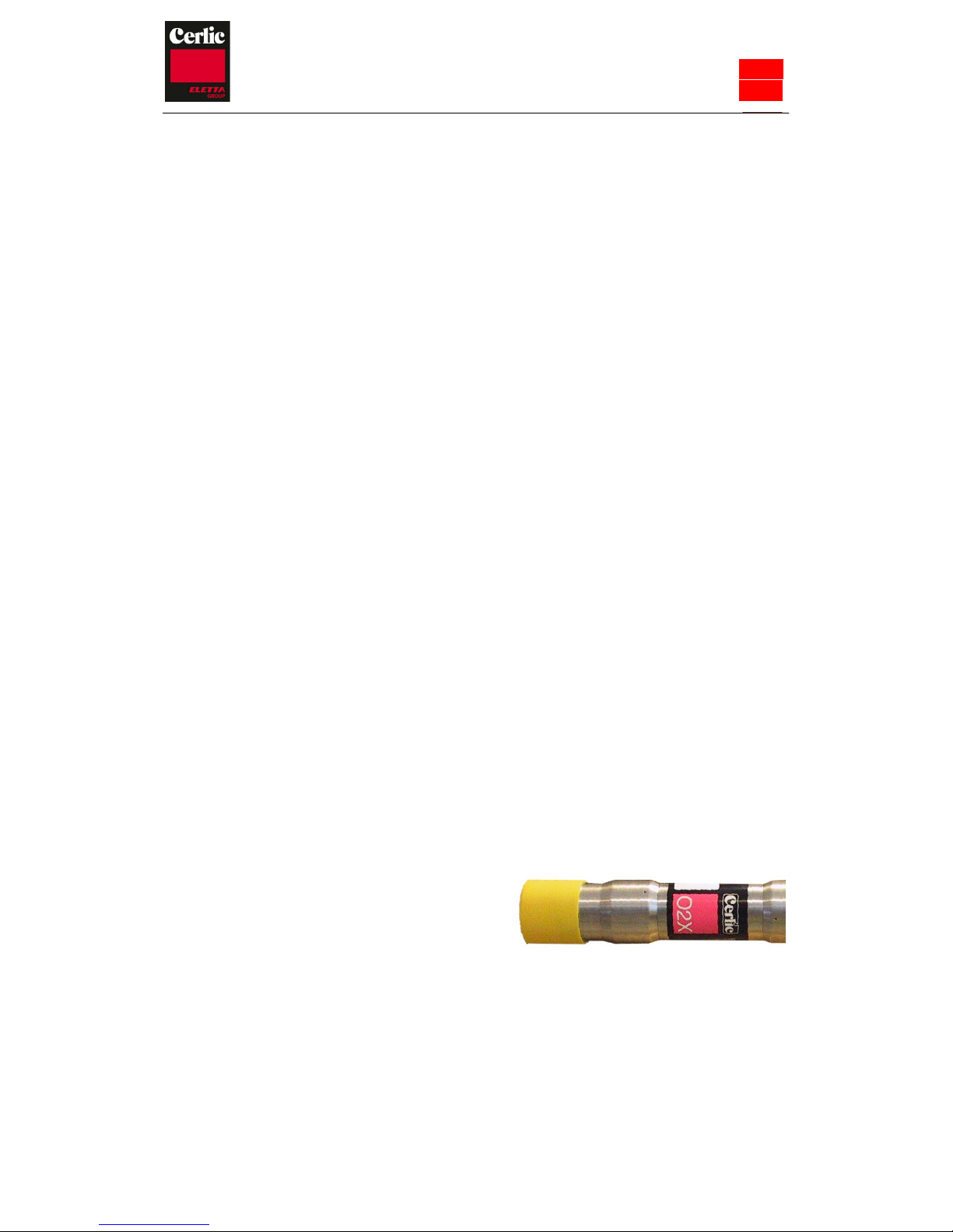
The O2X DUO sensor is manufactured with SS2343 (316SS) stainless steel. Built-in
flushing nozzles allow for the most accurate readings with little maintenance. The
electronics is protected in the rugged casing, ensuring its reliability in very demanding
environments.
The sensor has a fixed, shielded 10 m (33’) M12 cable used for signal transmission
between the sensor and the BB1/BB2 control box. The cable sheath is made of Hytrel
and is highly resistant to aggressive materials and fluids.
3.
Measuring principle
Clark cell, The electrode is a Clark type electrode with FEP membrane . The Clark cell
detects the oxygen though its reduction at the Gold electrode. The sensor consists of a
Gold cathode and Silver anode. A membrane covers the gold & silver electrodes and
blocks access of solids to the electrodes. Only dissolved gases such as oxygen can pass
thru the membrane, hence the reduction current responds to the oxygen concentration.
Active components included in the electrode are treated to maximize their life span.
Inside the electrode there is also a temperature sensor mounted in a way that minimizes
problems with temperature adjustments. This provides compensation of the electrode
due to temperature changes. There is a connector on the electrode for the O2X amplifier
cable. The temperature can be read on the BB1/BB2 and can be used as secondary
signal when an O2X sensor is configured to use two mA outputs. The temperature
measurement is not a precision measurement but should rather be seen as an indication.
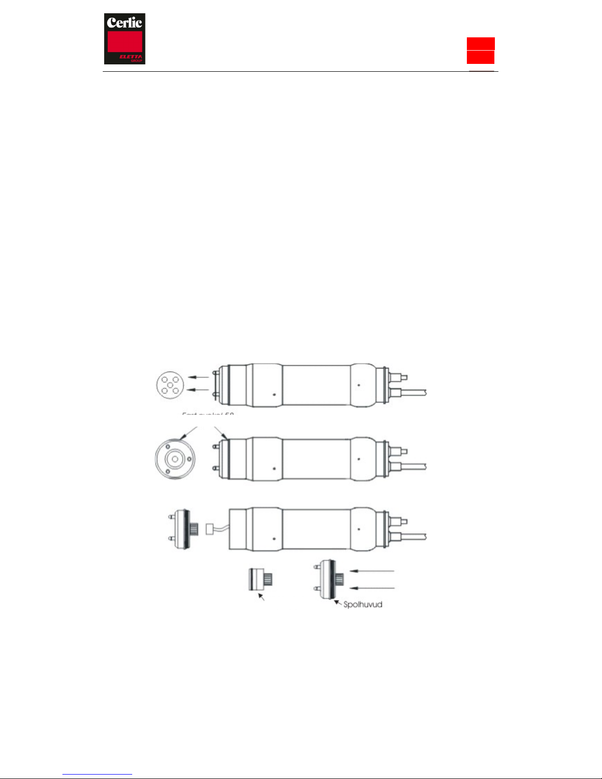
Optical cell, The optical cell is using phase shift technology to determine the oxygen
concentration. A special coating is applied to the acrylic disc in the top of the optical
electrode and called sensor cap in the manual. The optical cap is not sensitive to UV
light, but it is recommended when doing an air calibration to have the sensor in the
shade. The Clark & Optical cells can be interchanged in the O2X DUO sensor but an
air calibration must be preformed. There is a connector on the electrode for the O2X
amplifier cable. The temperature can be read on the BB1/BB2 and can be used as
secondary signal when an O2X DUO sensor is configured to use two mA outputs. The
temperature measurement is not a precision measurement but should rather be seen as
an indication.

- 4 -
O2X
DUO
4.
Unpacking the sensor
The unit has been tested and approved before delivery from the supplier. Please check
to confirm that no visible damages occurred during shipment.
Damages
If damages occurred during shipment, immediately contact the forwarder as well as
your Cerlic representative. The shipment can be returned only after contact has been
made with Cerlic.
Packaging
The original packaging is designed to protect the equipment and should be used for
storage or if the goods must be returned.
Content
Please check that the content corresponds to your order and packing list.
You will also need an electrode (below) to get the sensor working:
Optional parts for O2X DUO:
•Clark Electrode cartridge.
P/N
11805160
•Optical Cell cartridge 10306099
•Protection plates for Electrodes/Optical Cells Membranes 10305470
•Sensor Holder 11205541
•Telescopic Rod, 3 sections, Fiberglass 4 Meter (13,1’) 20205652
•Stainless steel Handrail Mounting bracket X, including rod holder 11205539
•Adjustable SS slide rail and sensor holder 66 mm 11205600
•Solenoid valve for flushing, 230 VAC
Inlet hose ∅∅16mm (5/8”) , to sensor
∅∅
8mm (1/4”)
11705516A
•Solenoid valve for flushing, 115 VAC
Inlet hose ∅∅16mm (5/8”) , to sensor
∅∅
8mm (1/4”)
11705516B
•Aluminum mounting plate predrilled for BB2 or solenoid valves
10305532
and connection boxes w/ u-bolts.
•Aluminum mounting plate predrilled for BB2 and solenoid valves
10305851
and connection boxes w/ u-bolts.
•10 meter (33 ft) M12 extension cable with plug-in connectors. 20805510
•30 meter (100 ft) M12 extension cable with plug-in connectors. 20850727
•Connection box for two sensors to one BB1/BB2 control box with
11505748
1m. (3 ft) cable to connect to BB1/BB2
•Connection box for four sensors to one BB1/BB2 control box with
11505785
1m (3 ft.) cable to connect to BB1/BB2

- 5 -
O2X
DUO
5.
Mounting the sensor
Cable Connections
Connect the sensor to the BB1/BB2 control box using the attached M12 connector on
the end of the sensor cable. In the event that two sensors are to be connected to the same
BB1/BB2 control box, use the Y-splitter (P/N 21505534) or 4-way Connection box
(P/N 11505785).
NOTE! Never try to turn the M12 connector housing on the cable to fasten or remove
the connector, only the fluted ring at the top of the M12 connector shall be turned.
Dielectric paste can be applied to the connector for corrosion protection.
The O2X DUO sensor is mounted on a telescopic fibreglass rod and placed in a
mounting bracket that fastens to a handrail, please refer to the Appendix 1 for further
details. As an alternative way of mounting the sensor, an adjustable SS slide rail holder
is available, please refer to the Appendix 2 for further details.
Note! For best DO measurement, the rod shall be mounted at an angle of 5° – 30°
from vertical.
Installation Tips
•Adjust the rod so that the sensor is at least 30 cm (12”) below the liquidsurface
or the lowest water level in decant applications (SBR’s) to prevent the sensor
from coming out of the liquid.
•In an aeration tank, ensure that the sensor is not directly above a diffuser head.
To obtain the most representative dissolved oxygen level, the sensor should be
installed on the backside of the rolling diffuser action.
•In an aeration basin, flushing may not be required if the tank is well agitated. To
verify the need for flushing, remove the sensor from the liquid after it has been
in the liquid for several days. If the sensor is coated with solids, flushing with
water or compressed air is recommended.
NOTE! The sensor is delivered with the
electrode uninstalled. A yellow plastic cap
protects the electrode connection plug and the
flushing nozzle in the transmitter. The plastic
cap must be removed and the electrode must
be installed and calibrated before the
transmitter is submerged into water (refer to
Section 7). Retain the yellow cap as it may be
used as protection later. Do not press on the
top of the cap if the electrode is installed.

- 6 -
O2X
DUO
6.
Removing the sensor
The SS sensor housing may not be opened except by Cerlic service personnel.
Opening the sensor housing will void factory warranty.
The sensor is removed in the following steps:
•Disconnect the sensor cable from the BB1/BB2 control box and the flushing hose
from the solenoid.
•Open the SS safety clamp, and pull the telescoping rod out of the SS handrail
mounting bracket.
•Make sure all water inside the rod & pvc sensor holder is drained.
•Clean the sensor and telescoping rod with a brush or clean cloth. Do not use a wire
brush!
•Open the black plastic sensor to rod adaptor.
•Flush the inside of the telescoping rod with clean water.
•Install the red protective cap (or a small plastic bag) on the M12 sensor cable
connector.
•Pull the flushing hose out of the rod first and then the M12 cable.
•Blow compressed air through the flushing hose to get rid of the water in the hose
and the sensor.
7.
Changing or installing a new electrode/cell
The electrode/cell can be both assembled and disassembled without special tools. Do
not clamp the SS sensor housing or the cable when installing or removing the SS
flushing head.
Please note: The new optical cell can be mounted on all sensors with serial number
higher than 7-25-078 bought later than 1 sept 2014. For older models please
contact Cerlic.
Removing an old electrode/cell:
•Make sure the automatic flushing is turned off.
•If using the SS protection plate, you must remove it before changing the
electrode/cell. Remove the flushing head by rotating it counterclockwise.
•Make sure the electrode/cell housing is dry. Water may come into the
housing when the flushing head is removed.
•Unplug the electrode/cell. Remove the electrode from the flushing head by
pressing firmly with your fingers on the backside of the electrode near the cable
connector.
•Confirm that the O-ring that seals the flushing head is installed in the proper
position in the SS sensor body.
•Screw the flushing head back into the sensor but do not screw it in to tightly.

- 7 -
O2X
DUO
EElk
•If a new electrode is not to be installed, then the yellow plastic cap shall be
mounted to protect the electrode connection plug and the flushing nozzles on the
sensor.
Installing a new electrode/cell:
•Loosen and remove the SS flushing head.
•Remove the cable connector from the electrode/cell and clean the connector.
•Use a new o-ring, 31.6x2.4 mm EPDM, on the electrode when exchanging the
electrode.
•Plug the electrode/cell cable into the connector on the top of theelectrode.
•Install the new electrode/cell into the SS flushing head. Don’t touch the cap
lens on the electrode/cell when installing.
•For the optical cell, the grooves in the electrode must be adapted to the holes for
the flush pipes.
•Tighten the SS flushing head and mount the protection plate, if needed. See
below the instructions on mounting the protection plate.
•A new air-calibration must be performed whenever the electrode/cell is changed.
For the optical cell also a 0-calibration shall be done.
•The date when the electrode/cell is changed shall be entered in thecalibration
menu.
Mounting the protection plate
First: remove the small o-rings mounted in the groove at the top of the three flushing
nozzles. Bend the plate slightly and press it down between the flushing nozzles and into
the grooves. Confirm that the plate fits into the notches on the flushing nozzles. Do not
remove a flushing nozzle in order to mount the protection plate. The nozzles are
fastened with a special locking glue.
Wrench
Electrode
Flushing head

- 8 -
O2X
DUO
8.
Cleaning the Sensor
The sensor is equipped with built-in flushing nozzles. The nozzles are used to direct the
cleaning medium, compressed air or water, via a flushing hose that is connected to the
top of the sensor. The air or liquid is controlled with a solenoid valve that is wired into
the BB1/BB2 control box. Please refer to the technical description for allowed pressure.
Note! Pay attention to the requirements for protection against backflow, according to
the EN 1717 standard for drinking water devices. If possible, use plant reuse water or
effluent water for cleaning.
Flushing must be activated in the “Settings” menu in the BB1/BB2 control box:
•Select the O2X DUO sensor in the Main Menu by using the or buttons,
•Press ENTER for five seconds to enter the Sensor Menu.
•Use the arrows to select “Cleaning” and press ENTER.
•If the sensor is to be cleaned as master, i.e. it has its own relay, then set the
“Cleaner” setting to “flush”, specify the cleaning interval in minutes, and the
flush time in seconds. If the sensor is to be cleaned as a slave, along with
another sensor, then these parameters are set for the sensor being the master.
Specify the freeze time in seconds after the flush for recover.
•If the sensor shall be cleaned as master, specify the relay to be used according to
the wiring inside the control box. For example, if the solenoid is wired to relay
#1, select “#1” for flushing. If the sensor is to be cleaned as a slave, specify
“Along #1” or “Along #2” depending on what relay the master sensor uses.
•For sensors configured as masters, “Next time” displays the next time flush will
be activated, pushing ENTER will set it to current time and start cleaning
cycle.
•Our recommendation is max flushing one time/hour and at max 2 bars pressure.
•Flush as little as possible, flushing wears the surface of the electrode/cell.
Excessive flushing reduces the lifetime of theelectrode/cell.
•Try flushing twice per day (720 minutes interval, 5 seconds length). If this
doesn’t keep the electrode/cell clean, first reduce the interval, then increase the
flushing time.
•Never flush when the electrode/cell is not installed.
•When the electrode/cell is not installed, the yellow plastic cap should be kept on
the end of the sensor for protection.
Flushing
Flushing tube
Sensor cable

- 9 -
O2X
DUO
Cleaning the Flushing Nozzle
If the flushing nozzle becomes plugged, removing the flushing head and backflush the
nozzles with clean water. Before removing the flushing head, close the valve for the
flush water source. Place a ½” hose over the flush nozzle and carefully open the water
valve. The pressure should clear the nozzle of solids. If backflushing does not work
initially, try cleaning the three flushing nozzles with a needle or wire. Try backflushing
the nozzles again as described above until clean water comes out.
Mounting plate for solenoid valves
To provide an easy mounting of solenoid valves for the built-in flushing nozzles Cerlic
offers a predrilled Aluminum handrail mounting plate. The Mounting plate is fixed to
the rail using two u-bolts.
Mounting plate P/N 10305533 for one or two solenoids, outside US version P/N 11705516A
(11705516 B US Version) and a connection box P/N 11505748.
9.
Sensor display
By simultaneously pressing and ENTER you change between BB1/BB2 main menu
and the sensor information display for the selected sensor. O2X DUO sensor has two
information displays, the first menu shows: measured DO value, current temperature of
the electrode in air, the solubility DO value in air for this air temperature, and the
“slope” of the electrode at the last air calibration. The second menu display shows: the
date of the last calibration and the date the electrode was replaced orchanged.

- 10
O2X
DUO
10.
Menu for O2X DUO Sensor
Use or to select the sensor on the main display. The menu for the selected sensor
is accessed by pressing ENTER for five seconds. If the selected sensor is not active (the
text No transmitter is shown) a warning is displayed that asks you to make another
choice in order to show the sensor menu.
Settings
Tag
Name of the sensor (10 characters) shown on the main display.
I--Time
Integration time or dampening
--
can be set up to 999 seconds.
Decimals
1 or 2 for display and menu.
Analog
”None” , ”Out1”, ”Out2”, ”Out3”, ”Out4”, ”Out1+2”, or ”Out3+4”.
Pick which analog output(s) to be used with this sensor.
Second
”Temp” or ”=Prim”. If two are chosen above, the first will always
give the primary value or DO reading according to the sensors
selected scale. The second will either give the temperature
scaled as stated below, or the same signal (primary value) as
the first channel. The temperature is additional information, not
a precision measurement.
Temp
0--
Temperature scaling, value that will give max output on second
channel. Default is 100 C but can be adjusted????
Calibrate
Airpres.mB
Specify within 10 mBar. Go to weather station on internet to
obtain for your zip code or location.
Calibrate
”No”, ”Zero”, or ”Air”. Select what calibration to do.
Temp (info)
Shows actual temperature in the electrode
Test (info)
Shows actual dissolved oxygen level
Setvalue
Theoretical reading in air at current temperature and with the
air pressure entered above. Should be the same as “test”
immediately after the calibration
Slope
Slope of the electrode/cell at last air calibration.
This value is an indication of the life of the electrode and it is
normally over 80 for a well functioning Clark electrode. But
there is nothing that eliminates the possibility of an electrode
functioning well at lower values. However at values below 50 it
is recommended to replace the Clark electrode.
Calibrated
Date of last air calibration.
New eletcr.
Date when electrode/cell was last changed. Push ENTER to edit the
date, then ENTER again to store it.

- 11
O2X
DUO
Cleaning
Press ENTER to go to Cleaning program
Cleaner
”None”, ”Flush”, or ”Brush”. Do not select “Brush” since this
does not exist for the O2X sensor
Interval min
0
--
999
minutes,
time
between
cleaning
cycles
Length sec
0
--
999
seconds,
duration
of
flushing
cycle
Freeze sec
0
--
999
seconds,
extra
freeze
time
of
output
signal
after
a
flushing cycle
so sensor can go back to the orginal values.
Relay
”
--
”,
”#1”,
”#2”,
“Along
#1”,
or
“Along
#2”.
Select
relay
to
operate
solenoid for flush cycle, if this sensor is a master with its own
relay, or relay used by master, if this sensor is a slave.
These are the same relays used for “Alarm relay” below
Next time
The next scheduled cleaning time. Pushing “Enter” on this line
will reset the time to current time and start a cleaning cycle.
This could be used to test the “Flush” cycle
.
Scale / Alarm
Max
0
--
99.9
mg/l,
measured
value
equal
to
20
mA
output
signal.
Min
0
--
99.9
mg/l,
measured
value
equal
to
4
mA
output
signal.
Hi
--
Alarm
0
--
99.9
mg/l,
the
value
zero
inactivates
the
alarm
Low
--
Alarm
0
--
99.9
mg/l,
the
value
zero
inactivates
the
alarm
Alarm Relay
”--” ”#1”, ”#2”, or ”#1 and #2”. Check to make sure that the relay
is not being used for cleaning.
System
Type
Type of sensor, (read only)
Serial
Serial number of the sensor, (read only)
SoftW
Software version of the sensor, (read only)
Temp
Sensor temperature, (read only)
MaxTemp
The highest temperature the sensor has been exposed to, (read only)
Info
Press “ENTER” to go to “info” (read only)
MS0
SA value for zero sample
MS1
SA value for air sample
Cons 1
Calculated concentration at last air calibration
Ch1
Raw value for dissolved oxygen measurement
Ch2
Raw value for channel temperature measurement
Con
mg/l, This is what is displayed on main screen
Samp/s
Number of samples per second
Service
Not accessible for users.

O2X
DUO
- 12 -
11.
Calibration
It is important that the instrument has been turned on for about 30 minutes prior to
calibration so that the sensor and electronics can stabilize.
Zero Calibration
The sensor is zero calibrated at the factory, and does not need to be zero calibrated. We
do however recommend to do a new zero calibration when replacing the electrode since
half the job is then already done.
For Clark electrode: Remove the electrode before performing a zero calibration.
Refer to “Section 8 – Changing or installing a New Electrode”.
For Optical cell: Remove the black protective cover around the new cell contact. Use
the jumper to close the circuit, see fig. Plug in the cell.
Zero calibrating a sensor:
•Select the O2X DOU sensor in the Main Menu by using the or buttons.
•Press ENTER for approximately five seconds to enter the Sensor Menu.
•Use the arrows to select the “Calibration” sub menu, and press ENTER.
•Select “Calibrate”. Press ENTER.
•Use the arrows to select “Zero” (three choices can be done, Air/No/Zero). Press
ENTER.
•Wait for the zero calibration to finish (usually takes about ten seconds). A
dialog box saying "Calibration done" will come up after successful calibration,
Press Enter to return to the previous menu.
For Clark electrode: Install the electrode before performing an air calibration. Refer
to “Section 8 – Changing or installing a New Electrode”. Continue with “Air
calibrating a sensor”
For Optical cell: Disconnect the jumper again. Put the jumper on one of the pins for
future usage. Mount the protective cover. Plug in the cell.

O2X
DUO
- 13
Air calibrating a sensor
The most important thing to keep in mind while performing an air calibration is to
create a constant environment. The electrode/cell cartridge must be dry with no water
drops on the membrane or luminophore. Fill a bucket halfway with water. Place the
sensor ~1-1.5 ft above the water surface to create a humid environment and cover the
bucket with a towel. If rain and/or strong winds are present, the calibration procedure
could be disturbed. In this case shield the equipment so that it is protected from therain
or wind. An open plastic bag over the sensor may slow the calibration time down, but
is otherwise a good way to help maintain constant conditions.
•Select the O2X DUO sensor in the Main Menu by using the or buttons.
•Press ENTER for approximately five seconds to enter the Sensor Menu.
•Select the “Calibration” press ENTER.
•Enter the current air pressure in mBar. It is sufficient to specify the pressure
within 10 mBar (see table below for conversion from inHg to mBar).
•Select “Calibrate”. Press ENTER.
•Use the arrows to select “Air” (three choices can be made, Air/No/Zero). Press
ENTER.
•Wait for the sensor to be calibrated. A successful calibration will take anywhere
between 3 to 15 minutes for the sensor to stabilize. A dialog box saying
"Calibration done" will come up after successful calibration. Press “Enter” to
return to the calibration menu.
The following appear in the Calibration menu as read-only:
•Temp (info): Displays the current temperature of the sensor.
•Test (info): Displays the
current measured dissolved oxygen value.
Immediately after calibration and before the sensor is placed in the liquid, this
value should closely equal the solubility value. A reading outside of an
acceptable range may indicate that the electrode needs to bereplaced.
•Set value: Ideal solubility value calculated using temperature and airpressure.

O2X
DUO
- 14
Air pressure conversion
It is important to enter the correct air pressure before doing an air calibration. Air
pressure is measured in mBar (which is exactly the same as the SI-unit hPa).
Below is a formula and a table to convert from inHG to mBar (and thus to hPa).
12.
Scaling
mBar =
inHg
∗∗
1000
29.5
The “Scale / Alarm” menu allows the user to set the high and low limits for the 4-
20mA output signal. In addition, this menu allows the user to set high and low alarms
values that can be used to notify when the level has reached criticalpoints.
Max sets the 20 mA point output
Min sets the 4 mA point output (may be a negative value for special
applications)
Hi-Alarm sets the High Alarm set point, the value zero inactivates the alarm
Low-Alarm sets the Low Alarm set point, the value zero inactivates the alarm
InHg
mBar / hPa
29.2
990
29.3
993
29.4
997
29.5
1000
29.6
1003
29.7
1007
29.8
1010
29.9
1014
30.0
1017
30.1
1020
30.2
1024
30.3
1027
30.4
1030

O2X
DUO
- 15
13.
Technical description
O2X DUO P/N 11305473
Material SIS2343 (316SS)
Dimensions See section 13.
Weight 2,1 kg. (4.6 lbs)
Process connection Submerged
Max Depth 10 m (33 ft.)
Max temperature 50°C (122°F)
Measuring principles Clark electrode or Optical Cell
Cable, connection 5-pin M12-plug
Cable, length 10 m (33 ft.)
Cable, material Hytrel
Flushing, Pressure Clark electrode: Water 3 bar (45 psi)
and filtered air 2 bar (30 psi)
Optical cell: Air/water max 2 bar (30 psi)
Flushing hose, length 10 m (33 ft.)
Flushing hose, material PE-LD
Enclosure IP68 (NEMA 4X)
Certificate of conformity:
The O2X DUO sensors along with their central unit BB1/BB2 Control Box are in
conformance with the following EC Directive(s) when installed in accordance with the
installation instructions contained in the product documentation:
2014/35/EU Low Voltage Directive, LVD
2014/30/EU Electromagnetic Compatibility (EMC) Directive
The following standards have been applied:
Low Voltage Directive:
SS-EN-60950 1 Edition 2:2006 Information technology equipment - Part 1:
General requirements.
SS-EN-61010-1 Edition 3:2010 Electric equipment for measurement, control
and laboratory use – Security – Part 1: General requirements.

O2X
DUO
- 16
EMC Directive
SS-EN 61000-6-2 Edition 3:2005 Electromagnetic compatibility – Part 6-2:
Generic standards – Immunity for industrial environments.
SS-EN 61000-6-4 Edition 2:2007 Electromagnetic compatibility - Part 6-4:
Generic standards – Emission standard for industrial
environments.
14.
Dimensions
Appendix 1, Assembly of handrail mounting kit
Mount the Flexible Mounting Bracket on handrail diameter of 1 ¼”
– 2” (32-50 mm) Ø or square 1 1/8” – 1 5/8” (28-42 mm). The bent
lip on the mounting plate shall be on top and faced toward the
liquid or tank. Adjust the Mounting Bracket to the correct angle and
tighten the SS nuts. The bracket shall be fixed to the rail, and it
shall not be able to move it.

O2X
DUO
- 17
Example of a handrail
when no handrail is
available.
•Disassemble the plastic Rod guide and
place around the telescopic rod.
•Use the SS screws on bracket to tighten the
bracket to the rod.
•Insert the PVC bracket guide with the telescopic rod
into the SS mounting bracket. Make sure that the
bracket guide tracks are properly seated in the bracket.
•Fasten the safety-locking clamp.
•Check that the SS mounting bracket is safely fixed to
the handrail for the spring to work the way it is
intended.
•To make it easier to inspect and service the
instrument, wind up a couple of meters of the cable
and fasten it on the rail with attached cable tie.
•Hint on pick up: let the rod hang freely and lift it
straight up before you swing it over the rail.
•Pull the M12 cable and flush hose through the sensor holder and rod.
•Connect the telescoping fiberglass rod to the sensor with the two piece black plastic adapter.
•The adapter halves should be tightened until snug, which will leave about 1-2 mm (1/16")gap.
NOTE! The gap is required so the water can drain from the rod and sensor holder.
•Adjust the length of the telescopic sensor rod as necessary by twisting the 2 nuts while holding
the rod.
NOTE! Do not extend the rod sections beyond the black lines. This could lead to rod damage.

Appendix 2, Assembly of adjustable slide rail

O2X
DUO
- 19
Appendix 3, Support information
Before calling Cerlic support, please complete the information in this form and have it
ready.
Company Name
Phone
E-mail
Sensor Type
Position / Tag
First go to the BB1/BB2 menu, it is accessed by pressing and ENTER at the same
time for five seconds. Select “System” and press ENTER.
Version Serial
Box temp
Box heat
Leave the BB1/BB2 menu by pressing and ENTER at the same time. Use or
to select the sensor in the main display. Go to the sensor menu, it is accessed by
pressing ENTER for five seconds. Select “System” and press ENTER.
Type
Serial
SoftW
Temp
Select “Info”, then press “ENTER” to go to the “info” menu.
MS0
MS1
Cons 1
Ch1
Ch2
Con
Samp/s Leave the BB2 menu by pressing and ENTER at the same
time.

Appendix 4, Setup information
This sheet can be used to document the setup values of an O2X sensor.
Sensor Type
Position / Tag
In the System sub menu of the sensor menu the following information can be collected.
Serial
SoftW
In the Settings sub menu of the sensor menu the following parameters can be set.
I-time No
of decimals Analog
Second
In the Cleaning sub menu of the sensor menu the following parameters can be set. Cleaner
Cleaning interval
Cleaning length
Cleaning freeze
Cleaning relay
In the Scale / Alarm sub menu of the sensor menu the following parameters can be set. Max
Min
High-Alarm Low-
Alarm
Alarm Relay
Leave the BB2 menu by pressing and ENTER at the same time.
O2X
DUO
Table of contents
Other Cerlic Accessories manuals
Popular Accessories manuals by other brands

Leviton
Leviton OSC04-I installation instructions

Infinite Peripherals
Infinite Peripherals LINEA PRO 6 quick start guide

STI
STI Magnetrol Kotron 811 Installation and operating manual

Peg-Perego
Peg-Perego Primo Viaggio Adapter For Tak Instructions for use

Awntech
Awntech RF22 Owner's Manual & Installation Instructions

Leviton
Leviton AEHTK Installation instruction