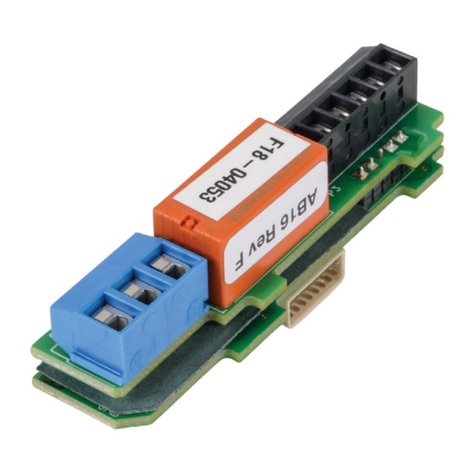
AutomationDirect Productivity2000 P2-HSI User manual

1
Sales 800-633-0405 www.productivity2000.com
®
Warranty: Thirty-day money-back guarantee. Two-year limited replacement.
(See www.productivity2000.com for details).
P2-HSI High-Speed Pulse Input
The P2-HSI High-Speed Input Module provides
dierential (line receiver, 5V max) and single
ended (5–24 V) inputs that accept up to 1MHz
of pulse/direction and quadrature signals on
each of the two independent input channels.
Additionally, four 5–24 VDC general purpose
high-speed inputs and four general purpose
5–24 VDC, 0.5A outputs are included for use
with any Productivity2000 System.
Warning .................................. 1
Connector Specifications..................... 1
QR Code ................................. 1
General Specifications ...................... 2
Status LEDs .............................. 2
Status Output Specifications .................. 2
Power Specifications ........................ 2
Single Ended (5–24 V) Input Specifications ...... 3
Differential (5V) Input Specifications ............ 3
Hot Swap Information ....................... 3
Module Installation ......................... 4
Wiring Options............................. 4
Frequency Measurement Details .............. 5
5V Encoder Inputs Wiring Diagram............. 6
24V Encoder Inputs Wiring Diagram............ 6
Status Inputs Wiring Diagram ................. 7
Status Outputs Wiring Diagram................ 7
Sinking I/O Wiring Diagram................... 8
Sourcing I/O Wiring Diagram ................. 8
Document Name Edition/Revision Date
P2-HSI-DS 4th Ed. 5/14/2020
Copyright 2018, AutomationDirect.com Incorporated/All Rights Reserved Worldwide
WARNING: To minimize the risk of potential safety problems, you
should follow all applicable local and national codes that regulate the
installation and operation of your equipment. These codes vary from
area to area and it is your responsibility to determine which codes
should be followed, and to verify that the equipment, installation, and
operation are in compliance with the latest revision of these codes.
Equipment damage or serious injury to personnel can result from
the failure to follow all applicable codes and standards. We do not
guarantee the products described in this publication are suitable for
your particular application, nor do we assume any responsibility for
your product design, installation, or operation.
If you have any questions concerning the installation or operation
of this equipment, or if you need additional information, please call
Technical Support at 770-844-4200.
This publication is based on information that was available at the
time it was printed. At AutomationDirect.com®we constantly strive to
improve our products and services, so we reserve the right to make
changes to the products and/or publications at any time without notice
and without any obligation. This publication may also discuss features
that may not be available in certain revisions of the product.
Connector Specifications
Connector Type IDC style header with latch, Omron XG4A-4034
Number of Pins 40 point
Pitch 0.1 in (2.54 mm)
QR Code
Use any QR Code reader application to
display the module’s product insert.

2Tech Support 770-844-4200www.productivity2000.com
General Specifications
Module Type Intelligent
Modules per Base 15 maximum*
I/O Points Used None, mapped directly to tags in CPU
Operating Temperature 0º to 60ºC (32º to 140ºF)
Storage Temperature -20º to 70ºC (-4º to 158ºF)
Humidity 5 to 95% (non-condensing)
Environmental Air No corrosive gases permitted
Vibration IEC 60068-2-6 (Test Fc)
Shock IEC 60068-2-27 (Test Ea)
Field to Logic Side Isolation 1800VAC applied for 1 second
Insulation Resistance >10MΩ @ 500VDC
Heat Dissipation 5.76 W
Enclosure Type Open Equipment
Module Location Any I/O slot in a Productivity2000 System
Field Wiring Use ZIPLink Wiring System. See “Wiring Options” on page 4.
EU Directive
See the “EU Directive” topic in the Productivity Suite Help File.
Information can also be obtained at:
www.productivity2000.com
Weight 90g (3.2 oz)
Agency Approvals UL 61010-1 and UL 61010-2-201 File E139594, Canada & USA
CE (EN 61131-2 EMC, EN 61010-1 and EN 61010-2-201 Safety)**
**Meets EMC and Safety requirements. See the D.O.C. for details.
Status Output Specifications
Status Outputs 4 sink/source
Output Signal Type, per Channel Select Current Sinking Current Sourcing
Operating Voltage¹ 5–24 VDC 5–24 VDC¹
Output Volts Maximum 36VDC 26.4 VDC¹
Output Current Maximum 500mA
Overcurrent Protection Short circuit detect and current limit with automatic retry
for each output
Output Self Limiting Current 1.2 to 2.4 A
Max Inrush Current Self limited
Output Voltage Drop 0.7 VDC @ 0.5 A
Thermal Protection Independent over temperature protection each output
Output Voltage Clamp During Inductive
Switching +45VDC -20VDC
Maximum OFF to ON Response 25μs²
Maximum ON to OFF Response 25μs²
NOTES:
1. Operating voltage of current sourcing outputs must be no greater than external
power.
2. Measured at 5VDC operating voltage, 0.5 A load current.
Power Specifications
External Power 24VDC -15% / +10%, Class 2
Maximum Voltage 26.4 VDC
Minimum Voltage 20.4 VDC
Current Consumption Excluding Outputs 50mA
Maximum Current Consumption Total of the 4
Status Outputs 2A
Status LEDs
Fault Status LEDs (F) 1, 2, 3 & 4 (one per status output)
Input LEDs (IN) 1A, 1B, 1Z, 2A, 2B, 2Z, IN3 & IN4 (one per status input)
Output Status LEDs (O) OUT1, OUT 2, OUT3 & OUT4
*Note: For complete system limits, please refer to the “Hardware and
Communication Limits” table in the Productivity Suite Help file, “Hardware
Configuration” topic (P050).
Note: Top row fault LED’s blinking indicates loss of external power.

3
Sales 800-633-0405 www.productivity2000.com
*Inputs are not limited to this speed but single ended signals are not usually reliable above 200kHz due
to cabling capacitance.
Important Hot-Swap Information
The Productivity2000 System supports hot-swap!
Individual modules can be taken offline, removed, and
replaced while the rest of the system continues con-
trolling your process. Before attempting to use the hot-
swap feature, be sure to read the hot-swap topic in the
programming software’s help file or our online documen-
tation at AutomationDirect.com for details on how to plan
your installation for use of this powerful feature.
Single Ended (5-24V) Input Specifications
Status Input Single ended inputs (8 pts: 1A, 1B, 1Z, 2A, 2B, 2Z,
3IN, 4IN)
Isolation Each input is isolated from other circuits
Input Volts Range 5–24 VDC
Input Volts Maximum ±34VDC, limited by protection
Input Impedance 1kΩ minimum, 5kΩ maximum
Inputs Rated Current
5–24 VDC, 16mA
5.2 mA typical @ 5VDC
22mA maximum @ 34VDC
Input Minimum ON Voltage 4.5 VDC
Input Maximum OFF Voltage 2.0 VDC
Input Minimum ON Current 5.0 mA
Input Maximum OFF Current 1.4 mA
OFF to ON Response Time 1A, 1B, 2A, 2B: 0.48 μs
1Z, 2Z, 3IN, 4IN: 6μs
ON to OFF Response Time 1A, 1B, 2A, 2B: 0.48 μs
1Z, 2Z, 3IN, 4IN: 6μs
Max. Input Frequency 1A, 1B, 2A, 2B: 1MHz
1Z, 2Z, 3IN, 4IN: 200kHz
Differential (5V) Input Specifications
Pulse Inputs Differential inputs (6 pts: 1A, 1B, 1Z, 2A, 2B, 2Z)
Isolation Each input is isolated from other circuits
Input Signal Type, per Channel Select Differential
Input Volts 5VDC
Input Volts Maximum +/-5.6 VDC, limited by protection
Input Impedance 200Ω minimum, 500Ω maximum
Input Rated Current 5VDC, 15mA (8mA typical, 15mA maximum)
Input Minimum ON Voltage 3.0 VDC
Input Maximum OFF Voltage 1.0 VDC
Input Minimum ON Current 5.0 mA
Input Maximum OFF Current 2.0 mA
OFF to ON Response Time 1A, 1B, 2A, 2B: 0.48 μs
1Z, 2Z, 3IN, 4IN: 6μs
ON to OFF Response Time 1A, 1B, 2A, 2B: 0.48 μs
1Z, 2Z, 3IN, 4IN: 6μs
Max. Input Frequency 1A, 1B, 2A, 2B: 1MHz
1Z, 2Z, 3IN, 4IN: 200kHz
NOTE: The voltage difference between the input pairs must be between 3-5.6 volts.
*The Z pulse input (1Z & 2Z) is capable of capturing a 1MHz wide pulse for the
purpose of resetting an encoder count but a 3 microsecond pause (300kHz) is
required between pulses.
Caution: If possible, remove field power prior to
proceeding. If not, then EXTREME care MUST be taken
to prevent damage to the module, or even personal injury
due to a short circuit from the live terminal block.

4Tech Support 770-844-4200www.productivity2000.com
Module Installation
1 Align
with slot
2rotate
to seated
position
WARNING: Do not apply field power until
the following steps are completed. See
hot-swapping procedure for
exceptions.
Locked Unlocked
Step One: Align module
catch with base slot and
rotate module into
connector.
Step Two: Pull top locking
tab toward module face. Click
indicates lock is
engaged.
Step Three: Attach
field wiring using the
ZIPLink wiring
system.
Wiring Options
1ZIPLink Feed Through Modules and Cables¹
ZL-RTB40
ZL-RTB40-1
ZIPLink Pre-wired Cables
0.5 m (1.6 ft) cable
1.0 m (3.3 ft) cable
2.0 m (6.6 ft) cable
ZL-CBL40S
ZL-CBL40-1S
ZL-CBL40-2S
3Accessories²
ZL-RTB-COM
TW-SD-SL-1
TW-SD-MSL-1
2
1.Cable + ZIPLink Module = Complete System
2. ZL-RTB-COM provides a common connection point for power or ground
ZL-RTB-40-1
ZL-RTB40

5
Sales 800-633-0405 www.productivity2000.com
Resolution of Frequency Measurements for “Fast Mode”
Input Frequency Sampling Period Resolution
1Hz to 1MHz 1000ms ±1 Hz
10Hz to 1MHz 100ms ±10 Hz
100Hz to 1MHz 10ms ±100 Hz
1MHz 1ms ±1000 Hz
Module Range: Target position range ± 2.147 billion (32-bit signed integer)
Inaccuracy of Frequency Measurements¹,² for “Slow Mode”
Input Frequency Step/Dir Quadrature 1X Quadrature 4X
1Hz ±0.002 Hz ±0.002 Hz ±0.002 Hz
10Hz ±0.009 Hz ±0.009 Hz ±0.009 Hz
100Hz ±0.015 Hz ±0.015 Hz ±0.015 Hz
1kHz ±1 Hz ±1 Hz ±1 Hz
10kHz ±100 Hz ±100 Hz ±100 Hz
100kHz ±1000 Hz ±1000 Hz ±1000 Hz
1MHz ±40000 Hz ±40000 Hz ±40000 Hz
Inaccuracy of Frequency Measurements¹,² for “Fast Mode”
Input Frequency Sampling Period Step/Dir Quadrature 1X Quadrature 4X
1Hz ±1 Second ±1 Hz ±1 Hz ±1 Hz
10Hz ±1 Second ±1 Hz ±1 Hz ±1 Hz
100Hz ±1 Second ±1 Hz ±1 Hz ±1 Hz
1kHz ±1 Second ±1 Hz ±1 Hz ±1 Hz
10kHz ±1 Second ±1 Hz ±1 Hz ±1 Hz
100kHz ±1 Second ±1 Hz ±1 Hz ±1 Hz
1MHz ±1 Second ±1 Hz ±1 Hz ±1 Hz
Inaccuracy of Frequency Measurements¹,²,³,⁴ for “Auto Mode”
Input Frequency Step/Dir Quadrature 1X Quadrature 4X
1Hz ±1 Hz ±1 Hz ±1 Hz
10Hz ±1 Hz ±1 Hz ±1 Hz
100Hz ±1 Hz ±1 Hz ±1 Hz
1kHz ±1 Hz ±1 Hz ±1 Hz
10kHz ±100 Hz ±100 Hz ±100 Hz
100kHz ±1000 Hz ±1000 Hz ±1000 Hz
1MHz ±10000 Hz ±10000 Hz ±10000 Hz
1. For stable input signal at given input frequency.
2. For total measurement error add the time base error to the tabulated error.
3. Maximum sample period: 1 second.
4. Minimum sample period: 0.001 seconds.
NOTE: Refer to the I/O Module Configuration Help File Topic (P212) in the
Productivity Suite Software for more information on Mode selections.
Inaccuracy of Frequency Measurements Due to Time Base Errors
25 MHz Crystal for Time Base
Inaccuracy at 25°C, Maximum ±30 PPM
Inaccuracy 0-60°C, Referenced to 25°C ±30 PPM
Inaccuracy Due to Aging, Maximum ±5 PPM/Year
Max. Time Base Inaccuracy 0-60°C and 10 Years Operation 0.01%
Frequency Measurements

6Tech Support 770-844-4200www.productivity2000.com
5V Encoder Inputs Wiring Diagram
D
A
A
1A
1A 169 Ohm
D
B
B
1B
1B 169 Ohm
D
C
C
1Z
1Z 169 Ohm
P2-HSI
Sensor
Encoder with 5V
Line Drivers
Belden 3105A shielded,
twisted pair,
low capacitance.
Dead head shield this end.
Tie shield to panel
ground this end.
To prevent damage to P2-HSI 5V inputs,
do not exceed 6.8V or 30 mA on inputs
1A, 1A, 1B, 1B, 1Z, 1Z, 2A, 2A, 2B, 2B, 2Z, & 2Z.
B
C
E
A
+
-1A
+1A 2K Ohm
-1B
+1B 2K Ohm
-1Z
+1Z 2K Ohm
P2-HSI
B
C
E
B
B
C
E
Z
-
Sensor Belden 3105A shielded,
twisted pair,
low capacitance.
Dead head shield this end.
Tie shield to panel
ground this end.
+
5VDC to 24VDC
24V Encoder Inputs Wiring Diagram

7
Sales 800-633-0405 www.productivity2000.com
Status Inputs Wiring Diagram
B
C
E
A
+
IN3+
IN3-
IN4+
IN4-
2K Ohm
2K Ohm
-1Z
+1Z
-2Z
+2Z
2K Ohm
2K Ohm
P2-HSI
-
B
C
E-
Sensor
Sensor
+
Sinking Field Device
Sourcing Field Device
+
5VDC to 24VDC PWR+
D
S
SNK
SRC
OUT1
+
LOAD
D
S
SNK
SRC
OUT2
D
S+LOAD
SNK
SRC
OUT3
D
S+LOAD
SNK
SRC
OUT4
+
LOAD
PWR-
+
24VDC
+
+
5VDC
to
24VDC
When 2nd power supply is used,
negative terminal must
be tied to PWR- terminal.
Sinking
Outputs
Sourcing
Outputs
Drivers
P2-HSI
Status Outputs Wiring Diagram

8Tech Support 770-844-4200www.productivity2000.com
Sinking I/O Wiring Diagram Sourcing I/O Wiring Diagram
+1A
+1B
+1Z
+2A
+2B
+2Z
IN3+ IN4+
OUT1
SNK
OUT2
SNK
LOAD
OUT4
SNK
+
+
24
VDC
5VDC
to
24VDC
Panel
GND.
LOAD
OUT3
SNK
LOAD
LOAD
Do not exceed 6.8V on these inputs
OUT1, OUT2, OUT3, & OUT4
SNK are 500mA Max. Load
1A OUT1
SRC
OUT1
SNK
OUT2
SNK
OUT2
SRC SH SH
OUT3
SNK
OUT3
SRC
1A 1B 1B 1Z 1Z 2A 2A 2B 2B 2Z 2Z
-1A +1A OUT4
SNK
OUT4
SRC
PWR
+
PWR
-
IN
3+
IN
3-
IN
4+
IN
4-
-1B +1B -1Z +1Z -2A +2A -2B +2B -2Z +2Z
-1A-1A -1B -1Z -2A -2B -2Z IN3- IN4-
LOAD
OUT4
SRC
+
+
24
VDC
Panel
GND.
5VDC
to
24VDC
OUT1
SRC
OUT2
SRC
LOAD
OUT3
SRC
LOAD
LOAD
Do not exceed 6.8V on these inputs
OUT1, OUT2, OUT3, & OUT4
SRC are 500mA Max. Load
1A OUT1
SRC
OUT1
SNK
OUT2
SNK
OUT2
SRC SH SH
OUT3
SNK
OUT3
SRC
1A 1B 1B 1Z 1Z 2A 2A 2B 2B 2Z 2Z
-1A +1A OUT4
SNK
OUT4
SRC
PWR
+
PWR
-
IN
3+
IN
3-
IN
4+
IN
4-
-1B +1B -1Z +1Z -2A +2A -2B +2B -2Z +2Z
Table of contents
Other AutomationDirect Control Unit manuals

AutomationDirect
AutomationDirect Productivity2000 P2-08ND3-1 User manual

AutomationDirect
AutomationDirect D0-DEVNETS User manual

AutomationDirect
AutomationDirect D0-DCM User manual

AutomationDirect
AutomationDirect CLICK C0-08SIM User manual

AutomationDirect
AutomationDirect PSM24-BCM360S User manual

AutomationDirect
AutomationDirect IronHorse GSDA-AI-A8 User manual

AutomationDirect
AutomationDirect D2-DCM User manual

AutomationDirect
AutomationDirect CLICK C0-04TRS-10 User manual

AutomationDirect
AutomationDirect CLICK C0-08TR-3 User manual