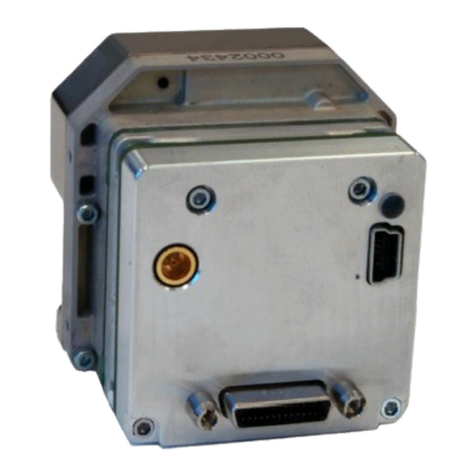
FLIR Lepton 1.6 Instruction Manual

FLIR LEPTON® Engineering Datasheet
The information contained herein does not contain technology as defined by the EAR, 15 CFR 772, is publicly available,
and therefore, not subject to EAR. NSR (6/14/2018).
Information on this page is subject to change without notice.
Lepton Engineering Datasheet, Document Number: 500-0659-00-09 Rev: 203
1
General Description
Lepton® is a complete long-wave infrared
(LWIR) camera module designed to interface
easily into native mobile-device interfaces and
other consumer electronics. It captures infrared
radiation input in its nominal response
wavelength band (from 8 to 14 microns) and
outputs a uniform thermal image with
radiometry
1
to provide temperature image with
measurements.
Lepton Features
2
•Integral shutter configurations
•Configurations with 25°, 50° and 57°
HFOV (f/1.1 silicon doublet)
•LWIR sensor, wavelength 8 to 14 µm
•Arrays with 80x60 and 160x120 active
pixels available
•Thermal sensitivity <50 mK
•Integrated digital thermal image
processing functions, including
automatic thermal environment
compensation, noise filters, non-
uniformity correction, and gain control
•Radiometric accuracy1(35°C blackbody)
oHigh gain: ±5C @ 25°C
oLow gain ±10C @ 25°C
•Radiometric Leptons1feature
temperature measurement including
per pixel and frame radiometric output
(TLinear) and Spotmeter
•Export compliant frame rate (< 9 Hz)
•SPI video interface
•Two-wire I2C serial control interface
1
Radiometric Leptons are 2.5 and 3.5.
•Uses standard cell-phone-compatible
power supplies: 2.8 V to sensor, 1.2 V to
digital core, and flexible IO from 2.8 V
to 3.1 V
•Fast time to image (< 1.2 sec)
•Low operating power
oNominally 160 mW
o800mW typical during shutter
event (~1s)
oLow power mode 5 mW
•RoHS compliant
•32- pin socket interface to standard
Molex or similar side-contact connector
Applications
•Mobile phones
•Gesture recognition
•Building automation
•Thermal imaging
•Night vision
2
All specifications subject to change without notice

FLIR LEPTON® Engineering Datasheet
The information contained herein does not contain technology as defined by the EAR, 15 CFR 772, is publicly available,
and therefore, not subject to EAR. NSR (6/14/2018).
Information on this page is subject to change without notice.
Lepton Engineering Datasheet, Document Number: 500-0659-00-09 Rev: 203
2
Contents
1INTRODUCTION .............................................................................................................................................................6
1.1 REVISION HISTORY.............................................................................................................................................................6
1.2 CONTACT US.....................................................................................................................................................................6
1.3 REFERENCES .....................................................................................................................................................................6
1.4 DEVICE OVERVIEW.............................................................................................................................................................8
1.5 KEY SPECIFICATIONS...........................................................................................................................................................9
1.6 SYSTEM ARCHITECTURE ....................................................................................................................................................11
2FUNCTIONAL DESCRIPTION .........................................................................................................................................12
2.1 FPA INTERFACE MODULE..................................................................................................................................................12
2.2 SYSTEM CONTROL (SYS CTRL)MODULE ...............................................................................................................................12
2.3 POWER MANAGEMENT MODULE .......................................................................................................................................13
2.4 SOFTWARE-BASED VIDEO PROCESSING (SVP CORE)MODULE..................................................................................................13
2.5 MEMORY SYSTEM (MEMORY SYS)MODULE.........................................................................................................................13
2.6 GENERAL PURPOSE PROCESSOR (GPP)................................................................................................................................13
2.7 VIDEO INTERFACE MODULE (VIDEO IF)................................................................................................................................13
2.8 ONE-TIME PROGRAMMABLE MEMORY (OTP)......................................................................................................................13
2.9 STATIC RANDOM-ACCESS MEMORY (SRAM) .......................................................................................................................13
2.10 GPIO INTERFACE MODULE (GPIO IF).................................................................................................................................14
2.11 VIDEO PIPELINE...............................................................................................................................................................14
2.11.1 NUC ....................................................................................................................................................................14
2.11.2 Defect Replacement...........................................................................................................................................14
2.11.3 Spatial / Temporal Filtering ...............................................................................................................................14
2.11.4 AGC ....................................................................................................................................................................15
2.11.5 Colorize ..............................................................................................................................................................15
2.12 MASTER CLOCK...............................................................................................................................................................15
3OPERATING STATES AND MODES ................................................................................................................................15
3.1 POWER STATES ...............................................................................................................................................................15
3.2 FFC STATES....................................................................................................................................................................18
3.3 GAIN STATES ..................................................................................................................................................................22
3.4 TELEMETRY MODES .........................................................................................................................................................23
3.5 RADIOMETRY MODES.......................................................................................................................................................29

FLIR LEPTON® Engineering Datasheet
The information contained herein does not contain technology as defined by the EAR, 15 CFR 772, is publicly available,
and therefore, not subject to EAR. NSR (6/14/2018).
Information on this page is subject to change without notice.
Lepton Engineering Datasheet, Document Number: 500-0659-00-09 Rev: 203
3
3.5.1 Radiometry Enabled - TLinear ................................................................................................................................30
3.5.2 Radiometry Enabled –Flux linear...........................................................................................................................30
3.5.3 Radiometry Disabled ..............................................................................................................................................31
3.5.4 Radiometric Accuracy –Module.............................................................................................................................32
3.5.5 Radiometric Accuracy –System Considerations.....................................................................................................32
3.6 AGC MODES..................................................................................................................................................................34
3.7 VIDEO OUTPUT FORMAT MODES .......................................................................................................................................36
3.8 GPIO MODES.................................................................................................................................................................39
4INTERFACE DESCRIPTIONS...........................................................................................................................................40
4.1 COMMAND AND CONTROL INTERFACE .................................................................................................................................40
4.1.1 User Defaults Feature.............................................................................................................................................42
4.2 VOSPI CHANNEL .............................................................................................................................................................44
4.2.1 VoSPI Physical Interface .........................................................................................................................................45
4.2.2 VoSPI Protocol –Lepton 1.5, 1.6, 2.0 and 2.5.........................................................................................................46
4.2.3 VoSPI Protocol –Lepton 3.0 and 3.5 ......................................................................................................................54
4.2.4 VoSPI Protocol –Lepton 2 vs. Lepton 3 ..................................................................................................................62
5THERMAL CAMERA BASICS..........................................................................................................................................63
6MOUNTING SPECIFICATIONS .......................................................................................................................................65
6.1 SOCKET INFORMATION .....................................................................................................................................................66
6.2 MECHANICAL CONSIDERATIONS .........................................................................................................................................68
6.3 THERMAL CONSIDERATIONS...............................................................................................................................................69
6.4 OPTICAL CONSIDERATIONS ................................................................................................................................................69
7IMAGE CHARACTERISTICS............................................................................................................................................69
8SPECTRAL RESPONSE ...................................................................................................................................................71
9ELECTRICAL SPECIFICATIONS .......................................................................................................................................73
9.1 LEPTON PIN-OUT .............................................................................................................................................................73
9.2 DC AND LOGIC LEVEL SPECIFICATIONS .................................................................................................................................76
9.3 AC ELECTRICAL CHARACTERISTICS.......................................................................................................................................77
9.4 ABSOLUTE MAXIMUM RATINGS .........................................................................................................................................78
9.5 ELECTRONIC INTEGRATION CONSIDERATIONS.........................................................................................................................78
10 ENVIRONMENTAL SPECIFICATIONS .............................................................................................................................79
10.1 COMPLIANCE WITH ENVIRONMENTAL DIRECTIVES..................................................................................................................80
11 ABBREVIATIONS AND ACRONYMS...............................................................................................................................82

FLIR LEPTON® Engineering Datasheet
The information contained herein does not contain technology as defined by the EAR, 15 CFR 772, is publicly available,
and therefore, not subject to EAR. NSR (6/14/2018).
Information on this page is subject to change without notice.
Lepton Engineering Datasheet, Document Number: 500-0659-00-09 Rev: 203
4
Table of Figures
Figure 1. Lepton with shutter Camera (with and without socket).............................................................................8
Figure 2 - Lepton Architecture.................................................................................................................................. 11
Figure 3 - Lepton Detailed Block Diagram................................................................................................................ 12
Figure 4 - Lepton Video Pipeline Block Diagram...................................................................................................... 14
Figure 5 - State Diagram Showing Transitions among the Five Power States ........................................................ 16
Figure 6 - Lepton Power Sequencing........................................................................................................................ 18
Figure 7 - Examples of Good Uniformity, Graininess, and Blotchiness................................................................... 19
Figure 8 - FFC States.................................................................................................................................................. 21
Figure 9 - Relative Spatial Noise after FFC vs. Number of Integrated Frames ((defaults is 8) ............................... 22
Figure 10 - Hypothetical Illustration of Camera Output in counts vs. Camera Temperature in Radiometry-
enabled Mode ........................................................................................................................................................... 31
Figure 11 - Hypothetical Illustration of Camera Output vs. Camera Temperature in Radiometry-disabled Mode
................................................................................................................................................................................... 32
Figure 12 - Illustration of a Histogram for a 3x3 Pixel Area..................................................................................... 35
Figure 13 - Comparison of Linear AGC and Classic/Lepton Variant of Histogram Equalization............................. 36
Figure 14 - Built-in Color Palette .............................................................................................................................. 38
Figure 15 - Comparison of an Identical Image with Grayscale and a False-color Palette ...................................... 39
Figure 16 - VoSPI Flexible Clock Rate ....................................................................................................................... 45
Figure 17 - VoSPI I/O................................................................................................................................................. 45
Figure 18 - SPI Mode 3 (CPOL=1, CPHA=1) ............................................................................................................... 46
Figure 19 - SPI Bit Order (transmission of 0x8C08).................................................................................................. 46
Figure 20 - Generic VoSPI Packet.............................................................................................................................. 47
Figure 21 - Video Packet ........................................................................................................................................... 48
Figure 22 - Discard Packet......................................................................................................................................... 48
Figure 23 - Raw14 Mode: 1 video line per 160-byte payload.................................................................................. 49
Figure 24 - RGB888 Mode: 1 video line per 240-byte payload................................................................................ 49
Figure 25 - Frame Counter for Successive 80x60 Frames ........................................................................................ 51
Figure 26 - Valid Frame Timing (no loss of synchronization)................................................................................... 52
Figure 27 -Clock Too Slow - Failure to Read an Entire Frame Within the Frame Period ........................................ 53
Figure 28 - Intra-Frame Delay Too Long - Failure to Read Out an Entire Frame Before the Next is Available...... 53

FLIR LEPTON® Engineering Datasheet
The information contained herein does not contain technology as defined by the EAR, 15 CFR 772, is publicly available,
and therefore, not subject to EAR. NSR (6/14/2018).
Information on this page is subject to change without notice.
Lepton Engineering Datasheet, Document Number: 500-0659-00-09 Rev: 203
5
Figure 29 - Failure to Read Out an Available Frame ................................................................................................ 53
Figure 30 - Generic VoSPI Packet.............................................................................................................................. 55
Figure 31 - Segment and Packet Relationship to the 160x120 video image........................................................... 55
Figure 32 - Packet Header Encoding and an Example.............................................................................................. 56
Figure 33 - Discard Packet......................................................................................................................................... 57
Figure 34 - Raw14 Mode: 1 video line per 160-byte payload.................................................................................. 58
Figure 35 - RGB888 Mode: 1 video line per 240-byte payload................................................................................ 58
Figure 36 - Location of Telemetry Lines ................................................................................................................... 58
Figure 37 - Frame Counter for Successive Frames.................................................................................................... 60
Figure 38 - Valid Frame Timing (no loss of synchronization)................................................................................... 61
Figure 39 - Clock Too Slow - Failure to Read an Entire Frame Within the Frame Period ....................................... 61
Figure 40 - Intraframe Delay Too Long - Failure to Read Out an Entire Frame Before the Next is Available........ 62
Figure 41 - Failure to Read Out an Available Frame ................................................................................................ 62
Figure 42 - Illustration of Lepton Detector Time Constant...................................................................................... 64
Figure 43 - Lepton with Radiometry Camera Mounting Dimensions...................................................................... 65
Figure 44 - Two Commercially-available Sockets (both from Molex) Compatible with Lepton ............................ 66
Figure 45 - Both Sockets Mounted on a PCB............................................................................................................ 67
Figure 46 - Recommended Approach to Retaining Lepton in the end Application................................................ 68
Figure 47 - Normalized Response as a Function of Signal Wavelength for Lepton 1.5, 2.0 and 2.5 ...................... 71
Figure 48 - Normalized Response as a Function of Signal Wavelength for Lepton 3.0 and 3.5 ............................. 72
Figure 49 - Pinout Diagram (viewed from bottom of camera module) .................................................................. 73
Figure 50. Example of Lepton schematic. ................................................................................................................ 78

FLIR LEPTON® Engineering Datasheet
The information contained herein does not contain technology as defined by the EAR, 15 CFR 772, is publicly available,
and therefore, not subject to EAR. NSR (6/14/2018).
Information on this page is subject to change without notice.
Lepton Engineering Datasheet, Document Number: 500-0659-00-09 Rev: 203
6
1Introduction
1.1 Revision History
Revision
Date
Description of Change
100
05/03/2016
Lepton with Radiometry release
110
11/12/2016
Updates to include low gain mode feature details
200
03/21/2018
Consolidating all Lepton current configurations into one
datasheet. Older document numbers are 500-0771-01-09, 500-
0763-01-09, 500-0726-01-09.
201
04/06/2018
Corrected part number for Lepton 1.5. Minor editorial changes.
Added document number.
202
07/02/2018
Updated dimensions and weight.
203
08/28/2018
Clarified validity of scene dynamic range.
Updated EAR statement.
Clarified that THousing in telemetry is only supported for Lepton
2.5 and 3.5.
1.2 Contact Us
email:SBA[email protected]
http://www.FLIR.com
1.3 References
110-0144-04 Lepton Software Interface Description Document (pdf)
80x60 Lepton VoSPI Developer Guide (pdf)
110-0144-50 Lepton VoSPI Developers Guide (pdf) (For 160x120)
Lepton_Example_Schematic_CAD_r100.DSN (Cadence-Capture schematic CAD file)
Lepton_Example_Schematic_CAD_r100.pdf (Cadence-Capture schematic PDF file)
Lepton_Example_Schematic_CAD_r100.brd (Cadence-Allegro PCB layout CAD file)
102-PS245-75 Advanced Radiometry App Note (pdf)
Configuration
Mechanical IDD
1.5
500-0643-41.pdf
1.6
500-0690-41.pdf

FLIR LEPTON® Engineering Datasheet
The information contained herein does not contain technology as defined by the EAR, 15 CFR 772, is publicly available,
and therefore, not subject to EAR. NSR (6/14/2018).
Information on this page is subject to change without notice.
Lepton Engineering Datasheet, Document Number: 500-0659-00-09 Rev: 203
7
2.0
500-0659-41.pdf
2.5
500-0763-41.pdf
3.0
500-0726-41.pdf
3.5
500-0771-41.pdf

FLIR LEPTON® Engineering Datasheet
The information contained herein does not contain technology as defined by the EAR, 15 CFR 772, is publicly available,
and therefore, not subject to EAR. NSR (6/14/2018).
Information on this page is subject to change without notice.
Lepton Engineering Datasheet, Document Number: 500-0659-00-09 Rev: 203
8
Figure 1. Lepton with shutter Camera (with and without socket)
1.4 Device Overview
Lepton is an infrared camera system that integrates a fixed-focus lens assembly, an 80x60 or 160x120 long-wave
infrared (LWIR) microbolometer sensor array, and signal-processing electronics. Some configurations are also
provided with an integral shutter assembly that is used to automatically optimize image uniformity on a periodic
basis. Easy to integrate and operate, Lepton is intended for mobile devices as well as any other application
requiring very small footprint, very low power, and instant-on operation. Lepton can be operated in its default
mode or configured into other modes through a command and control interface (CCI).
Figure 1 shows a view of the Lepton with Radiometry camera as standalone and mounted in a socket.

FLIR LEPTON® Engineering Datasheet
The information contained herein does not contain technology as defined by the EAR, 15 CFR 772, is publicly available,
and therefore, not subject to EAR. NSR (6/14/2018).
Information on this page is subject to change without notice.
Lepton Engineering Datasheet, Document Number: 500-0659-00-09 Rev: 203
9
1.5 Key Specifications
Table 1- Key Specifications
All numbers are nominal unless tolerances are specified.
Available configurations
Part number
Array format
Horizontal field of view
Shutter
Thermal radiometry
Distortion (barrel)
Scene Dynamic range3-
High gain (Low gain)
Pixel pitch
Lepton 1.5: 500-0643-00
80 x 60
50°
No
-
<8%
-10 °C to +140 °C
17 μm
Lepton 1.6: 500-0690-00
80 x 60
25°
No
-
<3%
-10 °C to +140 °C
17 μm
Lepton 2.0: 500-0659-01
80 x 60
50°
Yes
-
<8%
-10 °C to +140 °C
17 μm
Lepton 2.5: 500-0763-01
80 x 60
50°
Yes
Yes
<8%
-10 °C to +140 °C
(-10°C to 450°C)
17 μm
Lepton 3.0: 500-0726-01
160 x 120
57°
Yes
-
<13%
-10 °C to +140 °C
12 μm
Lepton 3.5: 500-0771-01
160 x 120
57°
Yes
Yes
<13%
-10 °C to +140 °C
(-10°C to 400°C)
12 μm
Overview
Sensor technology
Uncooled VOx microbolometer
Spectral range
Longwave infrared, 8 μm to 14 μm
Video scan
Progressive
Effective frame rate4
8.7 Hz (exportable)
Thermal sensitivity
<50 mK (0.050°C)
Temperature compensation
Automatic. Output image independent of camera
temperature.
3
Scene Dynamic Range is specified at room temperature and may vary over ambient temperature. It is typically somewhat
reduced at lower operating temperature.
4
Lepton 1.5, 1.6, 2.0, 2.5 stream video at 26Hz with every 3 frames repeated (effectively 8.7Hz). Lepton 3.0 and 3.5 stream
segments of the images with effectively full frames at 8.7Hz. In this document, when referring to number of frames the
frame rate 26Hz is understood.

FLIR LEPTON® Engineering Datasheet
The information contained herein does not contain technology as defined by the EAR, 15 CFR 772, is publicly available,
and therefore, not subject to EAR. NSR (6/14/2018).
Information on this page is subject to change without notice.
Lepton Engineering Datasheet, Document Number: 500-0659-00-09 Rev: 203
10
Output format
User-selectable 14-bit, 8-bit (AGC applied), or 24-bit RGB
(AGC and colorization applied)
Solar protection
Integral
Thermal radiometric
accuracy (Lepton 2.5 and 3.5)
-High gain mode: Greater of ±5 °C or 5% (typical)
-Low gain mode: Greater of ±10 °C or 10% (typical)
Electrical
Input clock
25-MHz nominal, CMOS IO Voltage Levels in accordance with
Electrical Specifications, page 73.
Video data interface
Video over SPI
Control port
CCI (I2C-like), CMOS IO Voltage Levels in accordance with
Electrical Specifications, page 73.
Input supply voltage
(nominal)
2.8 V, 1.2 V, 2.5 V to 3.1 V IO
Power dissipation
Nominally 150 mW at room temperature (operating), 5 mW
(standby). For 2.0, 2.5, 3.0 and 3.5 650mW during shutter
event.
Mechanical
Dimensions [mm] (w × l × h)
Lepton 1.5 (without shutter): 8.47 × 9.67 × 5.62
Lepton 1.6 (without shutter): 8.47 × 9.69 × 8.84
Lepton 2.0 (with shutter): 10.50 x 11.70 x 6.37
Lepton 2.5, 3.0, 3.5 (with shutter): 11.50 x 12.70 x 6.835
Dimensions with socket
105028-101 [mm] (w × l × h)
Lepton 1.5 (without shutter): 10.78 × 10.60 × 5.92
Lepton 1.6 (without shutter): 10.78 × 10.60 × 9.15
Lepton 2.0 (with shutter): 10.78 x 11.70 x 6.68
Lepton 2.5, 3.0, 3.5 (with shutter): 11.50 x 12.70 x 7.14
Weight (typical)
Lepton 1.5, 2.0: 0.68 grams
Lepton 2.5: 1.02 grams
Lepton 3.0, 3.5: 0.91 grams
Environmental
Camera operating
temperature range
Lepton 1.5, 1.6, 2.0, 2.5, 2.0, 3.5: -10 °C to +80 °C
Lepton 2.0, 3.0: Shutter operation limited to -10 °C to +65 °C
Non-operating temperature
range
-40 °C to +80 °C
Shock
1500 G @ 0.4 ms

FLIR LEPTON® Engineering Datasheet
The information contained herein does not contain technology as defined by the EAR, 15 CFR 772, is publicly available,
and therefore, not subject to EAR. NSR (6/14/2018).
Information on this page is subject to change without notice.
Lepton Engineering Datasheet, Document Number: 500-0659-00-09 Rev: 203
11
1.6 System Architecture
A simplified architectural diagram of the Lepton camera module is shown in Figure 2.
Figure 2 - Lepton Architecture
The lens assembly focuses infrared radiation from the scene onto an array of thermal detectors with
17m or
12m pitch. Each detector element is a vanadium-oxide (VOx) microbolometer whose temperature
varies in
response to incident flux. The change in temperature causes a proportional change in each
microbolometer’s
resistance. VOx provides a high temperature coefficient of resistance (TCR) and low 1/f
noise, resulting in excellent
thermal sensitivity and stable uniformity. The microbolometer array is grown
monolithically on top of a readout
integrated circuit (ROIC) to comprise the complete focal plane array (FPA).
For shuttered configurations, the shutter assembly periodically blocks radiation from the scene and presents a
uniform thermal
signal to the sensor array, allowing an update to internal correction terms used to improve image
quality. For
applications in which there is little to no movement of the Lepton camera relative to the scene (for
example,
fixed-mount security applications), the shutter assembly is recommended. For applications in which
there is
ample movement (for example, handheld applications), the shutter assembly is less essential although still
capable of providing slight improvement to image quality, particularly at start-up and when the ambient
temperature varies rapidly. The shutter is also used as a reference for improved radiometric performance.

FLIR LEPTON® Engineering Datasheet
The information contained herein does not contain technology as defined by the EAR, 15 CFR 772, is publicly available,
and therefore, not subject to EAR. NSR (6/14/2018).
Information on this page is subject to change without notice.
Lepton Engineering Datasheet, Document Number: 500-0659-00-09 Rev: 203
12
The serial stream from the FPA is received by a system on a chip (SoC) device, which provides signal
processing and
output formatting. This device is more fully defined in Functional Description, page 12.
2Functional Description
A detailed block diagram of the Lepton camera module is shown in Figure 3.
Figure 3 - Lepton Detailed Block Diagram
2.1 FPA Interface Module
The FPA Interface module generates timing and control signals to the FPA. It also receives and deserializes the
digital data stream from the FPA. The output values of on-board temperature sensors are multiplexed into the
pixel data stream, and the FPA Interface module strips these out and accumulates them (to improve SNR).
2.2 System Control (Sys Ctrl) Module
The System Control module provides the phase-lock-loop (PLL) and generates all clocks and resets required for
other modules. It also generates other timing events including syncs and the internal watchdog timer.
Additionally, it provides the boot controller, random-number generator, and command and control interface (CCI)
decode logic.

FLIR LEPTON® Engineering Datasheet
The information contained herein does not contain technology as defined by the EAR, 15 CFR 772, is publicly available,
and therefore, not subject to EAR. NSR (6/14/2018).
Information on this page is subject to change without notice.
Lepton Engineering Datasheet, Document Number: 500-0659-00-09 Rev: 203
13
2.3 Power Management Module
The Power Management module controls the power switches, under direction from the System Control Module.
2.4 Software-based Video Processing (SVP Core) Module
The SVP Core module is an asymmetric multi-core digital signal processor (DSP) engine that provides the full video
pipeline, further described in Video Pipeline, page 14.
2.5 Memory System (Memory Sys) Module
The Memory System module provides the memory interface to all the other modules that require access to SRAM
and/or OTP.
2.6 General Purpose Processor (GPP)
The GPP is a central processing unit (CPU) that provides the following functionality:
•Servicing of CCI commands
•Initialization and configuration of the video pipeline
•Power management
•Other housekeeping functions
2.7 Video Interface Module (Video IF)
The Video Interface module receives video data and formats it for VoSPI protocol (see documents in References,
page 6).
2.8 One-Time Programmable Memory (OTP)
The OTP memory contains all the non-volatile data for the camera, including the software programs for the SVP
Core and GPP as well as calibration data and camera-unique data (such as serial number). There are no provisions
for directly writing to OTP memory outside of the Lepton factory, except the User Default values as described
below.
An optional User Default feature is available on some Lepton versions to configure the desired defaults (e.g. FFC
mode, radiometry configuration, etc.), and write these defaults once by the user to OTP. This feature removes the
needs for an initialization sequence at start-up to configure the desired run-time settings. See User Defaults
Feature, page 42.
2.9 Static Random-Access Memory (SRAM)
SRAM is the primary volatile memory utilized by all other modules.

FLIR LEPTON® Engineering Datasheet
The information contained herein does not contain technology as defined by the EAR, 15 CFR 772, is publicly available,
and therefore, not subject to EAR. NSR (6/14/2018).
Information on this page is subject to change without notice.
Lepton Engineering Datasheet, Document Number: 500-0659-00-09 Rev: 203
14
2.10 GPIO Interface Module (GPIO IF)
The General-Purpose Input / Output (GPIO) Interface module implements the GPIO pins, which can be runtime
configured (see GPIO Modes, page 39).
2.11 Video Pipeline
A block diagram of the video pipeline is shown in Figure 4.
Figure 4 - Lepton Video Pipeline Block Diagram
The video pipeline includes non-uniformity correction (NUC), defect replacement, spatial and temporal
filtering,
automatic gain correction (AGC), and colorization.
2.11.1 NUC
The non-uniformity correction (NUC) block applies correction terms to ensure that the camera produces a
uniform output for each pixel when imaging a uniform thermal scene. Factory-calibrated terms are applied to
compensate for temperature effects, pixel response variations, and lens-illumination roll-off. To compensate for
temporal drift, the NUC block also applies an offset term that can be periodically updated at runtime via a process
called flat-field correction (FFC). The FFC process is further described in FFC States, page 18.
2.11.2 Defect Replacement
The defect-replacement block substitutes for any pixels identified as defective during factory calibration or during
runtime. The replacement algorithm assesses the values of neighboring pixels and calculates an optimum
replacement value.
2.11.3 Spatial / Temporal Filtering
The image pipeline includes several sophisticated image filters designed to enhance signal-to-noise ratio (SNR) by
eliminating temporal noise and residual non-uniformity. The filtering suite includes a scene-based non-uniformity

FLIR LEPTON® Engineering Datasheet
The information contained herein does not contain technology as defined by the EAR, 15 CFR 772, is publicly available,
and therefore, not subject to EAR. NSR (6/14/2018).
Information on this page is subject to change without notice.
Lepton Engineering Datasheet, Document Number: 500-0659-00-09 Rev: 203
15
correction (SBNUC) algorithm which relies on motion within the scene to isolate fixed pattern noise (FPN) from
image content.
2.11.4 AGC
The AGC algorithm for converting the full-resolution (14-bit) thermal image into a contrast-enhanced image
suitable for display is a histogram-based non-linear mapping function. AGC Modes, page 34.
2.11.5 Colorize
The colorize block takes the contrast-enhanced thermal image as input and generates a 24-bit RGB color output.
See Video Output Format Modes, page 36.
2.12 Master Clock
In Lepton the master clock (MASTER_CLOCK) frequency is 25 MHz.
3Operating States and Modes
Lepton provides several operating states and modes, more completely defined in the sections that follow:
•Power States, page 15
•FFC States, page 18
•Gain States page 22
•Telemetry Modes, page 23
•Radiometry Modes, page 29
•AGC Modes, page 34
•Video Output Format Modes, page 36
•GPIO Modes, page 39
3.1 Power States
Lepton currently provides five power states. As depicted in the state diagram shown in Figure 5, most of the
transitions among the power states are the result of explicit action from the host. The automatic transition to and
from the over-temperature (Overtemp) state is an exception.

FLIR LEPTON® Engineering Datasheet
The information contained herein does not contain technology as defined by the EAR, 15 CFR 772, is publicly available,
and therefore, not subject to EAR. NSR (6/14/2018).
Information on this page is subject to change without notice.
Lepton Engineering Datasheet, Document Number: 500-0659-00-09 Rev: 203
16
Figure 5 - State Diagram Showing Transitions among the Five Power States
The power states are listed here:
•Off: When no voltage is applied, Lepton is in the off state. In the off state, no camera
functions are
available.
•Uninitialized: In the uninitialized state, all voltage forms are applied, but Lepton has not yet
been
booted and is in an indeterminate state. It is not recommended to leave Lepton in this state
as power is
not optimized; it should instead be booted to the on-state (and then transitioned
back to Shutdown if
imaging is not required).
•On: In the on state, all functions and interfaces are fully available.

FLIR LEPTON® Engineering Datasheet
The information contained herein does not contain technology as defined by the EAR, 15 CFR 772, is publicly available,
and therefore, not subject to EAR. NSR (6/14/2018).
Information on this page is subject to change without notice.
Lepton Engineering Datasheet, Document Number: 500-0659-00-09 Rev: 203
17
•Shutdown: In the shutdown state, all voltage forms are applied, but power consumption is
approximately 5
mW. In the shutdown state, no functions are available, but it is possible to
transition to the on state via
the start-up sequence defined in Figure 6. The shutdown sequence
shown in Figure 6 is the recommended transition back to the shutdown state. It is also possible
to transition
between shutdown and on states via software commands, as further defined in the
software IDD.
•Overtemp: The Overtemp state is automatically entered when the Lepton senses that its
temperature
has exceeded approximately 80 °C. Upon entering the Overtemp state, Lepton
enables a “shutdown
imminent” status bit in the telemetry line and starts a 10-second counter. If
the temperature of the
Lepton falls below 80 °C before the counter times out, the “shutdown
imminent” bit is cleared and the
system transitions back to the on state. If the counter does time
out, Lepton automatically transitions to
the standby state.
Power sequencing is as shown in Figure 6.

FLIR LEPTON® Engineering Datasheet
The information contained herein does not contain technology as defined by the EAR, 15 CFR 772, is publicly available,
and therefore, not subject to EAR. NSR (6/14/2018).
Information on this page is subject to change without notice.
Lepton Engineering Datasheet, Document Number: 500-0659-00-09 Rev: 203
18
Figure 6 - Lepton Power Sequencing
3.2 FFC States
Lepton is factory calibrated to produce an output image that is highly uniform, such as shown in Figure 7 (a),
when viewing a uniform-temperature scene. However, drift effects over long periods of time degrade uniformity,
resulting in imagery which appears grainier Figure 7 (b)) and/or blotchy (Figure 7 (c)). Columns and other pixel
combinations may drift as a group. These drift effects may occur even while the camera is powered off. Operation
over a wide temperature range (for example, powering on at -10 °C and heating to 65 °C without performing and
FFC) will also have a detrimental effect on image quality and radiometric accuracy.
For scenarios in which there is ample scene movement, such as most handheld applications, Lepton is capable of
automatically compensating for drift effects using an internal algorithm called scene-based non-uniformity
correction (scene-based NUC or SBNUC). However, for use cases in which the scene is essentially stationary, such

FLIR LEPTON® Engineering Datasheet
The information contained herein does not contain technology as defined by the EAR, 15 CFR 772, is publicly available,
and therefore, not subject to EAR. NSR (6/14/2018).
Information on this page is subject to change without notice.
Lepton Engineering Datasheet, Document Number: 500-0659-00-09 Rev: 203
19
as fixed-mount applications, scene-based NUC is less effective. In stationary applications and those which need
highest quality or quickly available video, it is recommended to periodically perform a flat-field correction (FFC).
FFC is a process whereby the NUC terms applied by the camera's signal processing engine are automatically
recalibrated to produce the most optimal image quality. The sensor is briefly exposed to a uniform thermal scene,
and the camera updates the NUC terms to ensure uniform output. The entire FFC process takes less than a
second.
Figure 7 - Examples of Good Uniformity, Graininess, and Blotchiness
Lepton provides three different FFC modes:
•External (default for shutter-less configurations)
•Manual
•Automatic (default for configurations with shutter)
In external FFC mode, FFC is only executed upon command, and it should only be commanded when the camera
is imaging an external uniform source of a known temperature. To ensure radiometric accuracy in this mode, the
user must explicitly update the radiometry shutter mode to "User" and input the temperature of the scene during
FFC via the CCI. If in imaging mode only and temperature measurement is not required (radiometry disabled), any
uniform source such as a uniform wall will suffice.
Manual FFC mode is also executed only upon command, except that when FFC is commanded, Lepton closes its
integral shutter throughout the process. Note that it is not necessary to ensure a uniform external scene of a
known temperature before commanding FFC in manual FFC mode because the shutter serves as the uniform
source and includes a temperature sensor with automatic input for radiometric measurements.

FLIR LEPTON® Engineering Datasheet
The information contained herein does not contain technology as defined by the EAR, 15 CFR 772, is publicly available,
and therefore, not subject to EAR. NSR (6/14/2018).
Information on this page is subject to change without notice.
Lepton Engineering Datasheet, Document Number: 500-0659-00-09 Rev: 203
20
In automatic FFC, the Lepton camera will automatically perform FFC under the following conditions:
•At start-up
•After a specified period of time (default of 3 minutes) has elapsed since the last FFC
•If the camera temperature has changed by more than a specified value (default of 1.5 Celsius degrees)
since the last FFC
The time trigger and the temperature-change trigger described above are both adjustable parameters via the CCI;
however, the default values are recommended under most operating conditions. Decreasing the temperature or
time interval to FFC more often will provide better radiometric accuracy, but the tradeoff is decrease in useful
camera output and radiometry readings due to the increased occurrence of FFC.
The current FFC state is provided through the telemetry line. There are four FFC states, enumerated below and
illustrated in Figure 8:
1. FFC not commanded (default): In this state, Lepton applies by default a set of factory-generated FFC
terms. In automatic FFC mode, this state is generally not seen because Lepton performs automatic
FFC at start-up.
2. FFC imminent: The camera only enters this state when it is operating in automatic FFC mode. The
camera enters “FFC imminent” state at a specified number of frames (default of 52 frames at 26Hz, or
approximately 2 seconds) prior to initiating an automatic FFC. The intent of this status is to warn the
host that an FFC is about to occur.
3. FFC in progress: Lepton enters this state when FFC is commanded from the CCI or when automatic
FFC is initiated. The default FFC duration is nominally 23 frames at 26Hz, in which case the camera
integrates 8 frames of output as the basis for the correction (the additional frames are overhead). It is
possible to configure the FFC to integrate fewer or more frames (from 1 to 128 in powers of 2).
Utilizing fewer frames obviously decreases the FFC period (with diminishing returns due to overhead)
whereas utilizing more frames provides greater reduction of spatial noise (also with diminishing
returns due to 1/f noise). Figure 9 quantifies the benefit. Radiometry readings are invalid during this
state.
4. FFC complete: Lepton automatically enters this state whenever a commanded or automatic FFC is
completed.
Lepton also provides an “FFC desired” flag in the telemetry line. The “FFC desired” flag is asserted under the same
conditions that cause automatic FFC when in automatic FFC mode. That is, the “FFC desired” flag is asserted at
start-up, when a specified period (default = 3 minutes) has elapsed since the last FFC, or when the sensor
temperature has changed by a specified value (default = 1.5 Celsius degrees) since the last FFC. In automatic
mode, the camera immediately enters “FFC imminent” state when “FFC desired” is true. In manual FFC mode and
This manual suits for next models
5
Table of contents
Other FLIR Control Unit manuals
Popular Control Unit manuals by other brands

Honeywell
Honeywell ControLinks S7999 Product data

Lindy
Lindy 25037 user manual

Viessmann
Viessmann VITOSOLIC 200 Installation and service instructions

schmersal
schmersal SRB 211ST Mounting and wiring instructions

Leviton
Leviton 73A00-4ZB Installation instructions and user guide

schmersal
schmersal SRB301ST/PCV.2 operating instructions

Festo
Festo CDSA-D1-VX Brief overview

ADTRAN
ADTRAN Total Access 300 quick start guide

Wolf
Wolf R33/4 DigiComfort (Theta) Wiring diagram, Installation and short operating instructions

Zener
Zener ECODRIVE 8000 Application guide

Mutable Instruments
Mutable Instruments Clouds Illustrated manual

Burkert
Burkert 5281 Series operating instructions