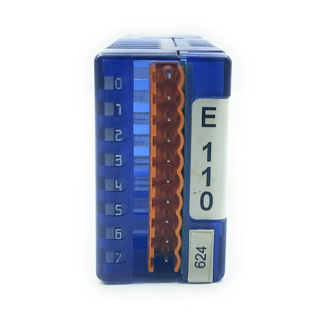
saia-burgess PCD2.W525 User manual

Hardware Manual
Document-No. 26-853 | Edition E2 | 2008-01-18
PCD2.W525 | PCD3.W525 Controls Division

Manual PCD2.W525&PCD3.W525│Document 26/853; Edition E2│2008-01-18
Saia-Burgess Controls Ltd.
Content
0-1
0
0 Content
0.1 Document history............................................................................................ 0-2
0.2 Trademarks..................................................................................................... 0-2
1 Hardware
1.1 General Information........................................................................................ 1-1
1.2 Conguration................................................................................................... 1-2
1.2.1 Module connections/LED .............................................................................. 1-2
1.2.2 How to congure the inputs........................................................................... 1-2
1.2.3 How to congure the outputs ........................................................................ 1-2
1.3 Function.......................................................................................................... 1-2
1.3.1 Power Supply................................................................................................ 1-2
1.3.2 Timing ........................................................................................................... 1-3
1.3.3 Filter.............................................................................................................. 1-3
1.4 Technical Data ................................................................................................ 1-4
A Appendix
A.1 Icons ............................................................................................................... A-1
A.2 Address........................................................................................................... A-2
0 Content

Manual PCD2.W525&PCD3.W525│Document 26/853; Edition E2│2008-01-18
Saia-Burgess Controls Ltd.
Content
0-2
0
0.1 Document history
Document-no Edition Changes Remarks
2007-03-31 pE1 complete Preliminary Edition
2007-11-15 E1 complete A few changes to pE1
2008-01-18 E2 Chapter
1.4 PCD3.W525 pluggable terminal:
wrong ordering number replaced
0.2 Trademarks
Saia®and Saia® PCD are registered trademarks of Saia-Burgess Controls AG
Technical modications and changes are subject to the state of technology
Saia-Burgess Controls AG, 2007.
© All rights reserved
Published in Switzerland

Manual PCD2.W525&PCD3.W525│Document 26/853; Edition E2│2008-01-18
Saia-Burgess Controls Ltd.
Introduction
Hardware
1-1
1
1 Hardware
1.1 General Information
PCD2/3.W525 is an analogue multipurpose module with four inputs and two outputs.
Each input and each output can be individually congured as one of the standard
industrial interface type like 0 … 10 V, 0 … 20 mA and 4 … 20 mA. In addition, the inputs
can be congured to support Pt/Ni1000 or Pt500 temperature sensors. Furthermore,
the module offers high exibility in selecting lter types and scaling ranges.
Inputs-14 Bit
● 4 Inputs. Every channel has four modes of operation (congurable by DIP-
Switches):
○ DifferentialVoltageInputs
0 … 10 V, resolution: 0.61 mV per LSB (14 Bit)
○ DifferentialCurrentInputs-measured in differential mode
0 … 20 mA, resolution: 1.2 μA per LSB (14 Bit)
4 … 20 mA, resolution: 1.2 μA per LSB (13.7 Bit)
○ Temperature
Pt1000, -50 … 400 °C, resolution: 0.1 °C
Pt500, -50 … 400 °C, resolution: 0.2 °C
Ni1000, -60 … 200 °C, resolution 0.1 °C
○ Resistance
0 … 2500 Ω, resolution 0.2 Ω
● Each channel can be congured to have a software based 50 Hz / 60 Hz lter
Outputs-12 Bit
● 2 Outputs. Every channel has three modes of operation (congurable by soft-
ware):
○ Voltage
0 … 10 V, resolution: 2.44 mV per LSB (12 Bit)
○ Current
0 … 20 mA, resolution: 4.88 μA per LSB (12 Bit)
4 … 20 mA, resolution 4.88 μA per LSB (11.7 Bit)
○ Highimpedance
Miscellaneous
● All I/O-Channels are galvanically isolated to the PCD and external power sup-
ply. (But all channels are galvanically connected to each other.)
● Every channel has two connection terminals.

Manual PCD2.W525&PCD3.W525│Document 26/853; Edition E2│2008-01-18
Saia-Burgess Controls Ltd.
Function
Hardware
1-2
1
1.2 Conguration
1.2.1 Module connections/LED
The connections of the module terminal are the following:
Description of the LED:
● Off: Module is not powered. Uext (24 V) is missing.
● On: Module is running without errors
● Blinking slow: Channel error (Over range/under range/short circuit/open load)
● Blinking fast: Uext is lower than specified (< 19 V)
1.2.2 Howtoconguretheinputs
Each input channel is congured by a DIP-Switch with four switches. The function of
each switch is the following:
Switch nr. Off On
1
2
3
4
Differential Mode
Gain=1
Single Ended Mode
Current Shunt On
Supply for external Resistors On
Gain=0.25
According to this table, the conguration for the different modes of operation is as fol-
lows:
Voltage mode
0...10 V Current mode
0...20 mA
4...20 mA
Temperature mode
Pt1000 (-50...400 ˚C)
Pt500 (-50...400 ˚C)
Ni1000 (-60...200 ˚C)
Resistor mode
0...2500 Ω
1.2.3 Howtoconguretheoutputs
Since the outputs are congured by software (with the corresponding FBox or FB),
there is no need to congure the mode of operation of the outputs with any kind of
jumpers or DIP-Switches.
1.3 Function
1.3.1 Power Supply
PCD2.W525 / PCD3.W525 has to be supplied externally! This power supply is gal-
vanically isolated to both, the PCD and the I/Os of W525. Furthermore, the design
allows using the same power supply for the PCD and for W525 without loosing the
galvanic isolation. These schematics show the different zones of isolation:

Manual PCD2.W525&PCD3.W525│Document 26/853; Edition E2│2008-01-18
Saia-Burgess Controls Ltd.
Function
Hardware
1-3
1
1.3.2 Timing
● Inputs
○ Internally, W525 nishes acquiring every 2 ms a new value for every
input channel
○ This value is always ready to be read by the PCD.
○ Dependent on the PCD speed, the transmission time of a single 16-Bit
scaled value (of a single input channel) takes typically 100 μs (on a
PCD2.M480) or 600μs (on a PCD2.M170)
● Outputs
○ Internally, W525 outputs the last received output value from PCD with a
maximum delay of 2 ms.
○ Dependent on the PCD speed, the transmission time of a single 16-Bit
scaled output value takes typically 100 μs (on a PCD2.M480) or 600 μs
(on a PCD2.M170).
1.3.3 Filter
●Inputs
There are two factors, which have ltering effects to the acquired values:
○ The base hardware lter with a time constant of 2ms. This lter attenu-
ates the input signal by 6 dB/decade at a cut-off frequency of 80 Hz.
○ The second inuence is caused by software and results in a delay of
the acquired value for 2 ms with a notch lter characteristics at 500 Hz if
no software based 50 Hz / 60 Hz lter is selected.
In case of use of a 50 Hz (60 Hz) lter, the notch lter frequency is 50 Hz
(60 Hz); the delay remains the mentioned 2ms.
●Outputs
There is only the hardware based lter with a time constant of 1 ms, which is
active

Manual PCD2.W525&PCD3.W525│Document 26/853; Edition E2│2008-01-18
Saia-Burgess Controls Ltd.
Technical Data
Hardware
1-4
1
1.4 Technical Data
Inputs
General:
Resolution: 14 Bit
Kind of Measurement: differential
Number of channels: 4
Galvanic isolated to PCD: yes
Galvanic isolated to external supply: yes
Galvanic isolated between other channels: no
Kind of connections: two wires per channel
How to congure mode of operation: by DIP-Switches
Accuracy at 25 °C: ± 0.2% max.
Accuracy repetitive: ± 0.05% max.
Temperature drift (0...55 °C) max.: ± 70 ppm/°C
Over voltage protection: ± 50 V min.
Over current protection: ± 35 mA min.
Common mode voltage max: ± 50 V min.
Common mode rejection ratio: 70 dB min.
Filter:
Time constant of hardware lter: 2 ms
Attenuation of software based 50 Hz Filter: 40 dB min. between 49.5 and 50.5 Hz
Attenuation of software based 60 Hz Filter: 40 dB min. between 59.5 and 60.5 Hz
Voltagemode:
Resolution range 0 … 10 V mode: 14 Bit; 0.61 mV per LSB
Currentmode:
Current shunt: 125 Ω
Resolution range 0 … 20 mA: 14 Bit; 1.22 µA per LSB
Resolution range 4 … 20 mA: 13.7 Bit; 1.22 µA per LSB
Temperature/Resistancemode:
Resolution for Pt1000; Range -50 … 400 °C 0.1 °C
Resolution for Pt500; Range -50 … 400 °C 0.2 °C
Resolution for Ni1000; Range -60 … 200 °C 0.1 °C
Resolution for Resistor; Range 0 … 2500 Ω 0.2 Ω
Power dissipation in temp. sensor / resistor: 2.5 mW max
Outputs
General:
Resolution: 12 Bit
Number of channels: 2
Galvanic isolated to PCD: yes
Galvanic isolated to external supply: yes
Galvanic isolated between other channels: no
Kind of connections: two wires per channel
How to congure mode of operation: by software (FBOX, FB)
Accuracy at 25 °C: ± 0.5% max.
Accuracy repetitive: ± 0.1% max.
Temperature drift (0...55 °C) max.: ± 70 ppm/°C.
Over current protection: short circuit protected
Time constant of lter: 1 ms
Voltagemode:
Max. load to guarantee specied accuracy: > 700 Ω
Resolution range 0 … 10 V: 12 Bit; 2.44 mV per LSB

Manual PCD2.W525&PCD3.W525│Document 26/853; Edition E2│2008-01-18
Saia-Burgess Controls Ltd.
Technical Data
Hardware
1-5
1
Currentmode:
Working resistance: < 600 Ω
Resolution range 0 … 20 mA: 12 Bit; 4.88 µA per LSB
Resolution range 4 … 20 mA: 11.7 Bit; 4.88 µA per LSB
General Data
Power consumption at I/O-Bus +5V: max. 40 mA
Power consumption at I/O-Bus V+: unloaded
Temperature range: 0...55 °C
External power supply
(It is possible and allowed to use the same power supply as the PCD itself is supplied with
– without losing the galvanic isolation of the I/Os!)
Operation voltage: 24 V ±4 V smoothed
Power consumption: max. 2.5 W (depends on output load)
Terminal: PCD2 Pluggable 14-pole screw terminal
(PCD2.W525; O no. 4 405 5002 0, will be
delivered with the module),
both for wires up to 1,5 mm²
PCD3 Pluggable 14-pole cage clamp terminal
(PCD3.W525; O no. 4 405 4998 0),
both for wires up to 1,5 mm²

Saia-Burgess Controls AG
Manual PCD2.W525&PCD3.W525│Document 26/853; Edition E2│2008-01-18
Appendix
2
A-1
Icons
A Appendix
A.1 IconsIcons
In manuals, this symbol refers the reader to further information in this manual or
other manuals or technical information documents.
As a rule there is no direct link to such documents.
This symbol warns the reader of the risk to components from electrostaticonents from electrostatic
discharges caused by touch.
Recommendation: at least touch the Minus of the system (cabinet of PGU
connector) before coming in contact with the electronic parts. Better is to use a
grounding wrist strap with its cable attached to the Minus of the system.
This sign accompanies instructions that must always be followed.
Classic
Explanations beside this sign are valid only for the Saia-Burgess PCD Classic
series.
xx7
Explanations beside this sign are valid only for the Saia-Burgess PCD xx7 series.

Saia-Burgess Controls AG
Manual PCD2.W525&PCD3.W525│Document 26/853; Edition E2│2008-01-18
Appendix
2
A-2
Address
A.2 Address
Saia-Burgess Controls Ltd.
Bahnhofstrasse 18
CH-3280 Murten / Switzerland
Telephone ++41 26 672 71 11
Telefax ++41 26 672 74 99
E-mail: [email protected]
Homepage: www.start-controls.com
Support: www.sbc-support.ch
This manual suits for next models
1
Table of contents
Other saia-burgess Control Unit manuals
Popular Control Unit manuals by other brands

Intermatic
Intermatic K4621 installation manual

AXIOMTEK
AXIOMTEK eBOX530-830-FL user manual

SSS Siedle
SSS Siedle FPM 611-02 Product information

TRIGA
TRIGA TR-RELAY-6 Installation and maintenance instructions

RoboMaster
RoboMaster Referee System user manual

Cooper
Cooper Scantronic 65 installation instructions