FARFISA INTERCOMS CD2131MAS User manual
ITALIANOENGLISHFRANÇAISESPAÑOLPORTUGUÊSDEUTSCH
ITALIANOENGLISHFRANÇAISESPAÑOLPORTUGUÊSDEUTSCH
Mi 2318/1 1
CODIFICATORE DIGITA-
LE SERIE MATRIX A 1, 2 O 4
PULSANTI
Pulsantierainacciaioantivandaloserie
Matrix con 1, 2 o 4 tasti in acciaio. Per-
mettediinviarechiamatesulineadigita-
leDUO.
Datitecnici
Alimentazionedalmodulo audio/video
Tempo azionamento serratura 3/6 sec.
Numero di chiamate 128
Dimensioni 1 modulo
Temperatura di funzionamento 0°÷+40°C
Massima umidità ammissibile 90% RH
Mi 2318/1
E
DIGITALIZADOR SERIE
MATRIX CON 1, 2 O 4 PULSADO-
RES
Placadecalledeaceroantivandalismo
serie Matrix con 1, 2 o 4 pulsadores de
acero. Permite de enviar llamadas en
la línea digital DUO.
Datostécnicos
Alimentación desde el módulo de audio/
vídeo
Tiempoaccionamientocerradura 3/6seg.
Número de llamadas 128
Dimensión 1 módulo
Temperatura de funcionam. 0°÷+40°C
Máxima humedad admisible 90% RH
MATRIX SERIES DIGITAL
ENCODER TO 1, 2 OR 4 PUSH-
BUTTONS
Matrixseriesanti-vandalismsteelpush-
buttonpanelwith1,2or4steelbuttons.
Used to send calls over DUO digital
line.
Technicalfeatures
Power supply from audio/video module
Door-opening time 3 / 6 sec.
Number of calls 128
Dimensions 1 module
Operating temperature 0°÷+40°C
Maximum humidity acceptable 90% RH
DIGITALISEURSERIEMATRIX
A1,2OU4BOUTONS-POUSSOIRS
Plaques de rue en acier antivandale,
série Matrix à 1, 2 ou 4 boutons-
poussoirs Permet d’adresser des
appelssur ligne digitaleDUO.
Données techniques
Alimentationdepuislemoduleaudio/vidéo
Délai d’activation de la gâche 3 / 6 sec.
Nombre d’appels 128
Dimensions 1 module
Température de fonction. 0°÷+40°C
Humidité max. admissible 90% RH
DIGITALIZADORSERIEMATRIX
COM1, 2 OU4 BOTÕES
Botoneiraemaçoanti-vandalismosérie
Matrix com 1, 2 ou 4 botões em aço.
Possibilita o envio de chamadas para
linhadigitalDUO.
Dados técnicos
Alimentaçãoapartirdomóduloáudio/vídeo
Tempo acionamento fechadura 3 /6 seg.
Número de chamadas 128
Dimensões 1 módulo
Temperatura de funcionam. 0°÷+40°C
Umidade máxima admissivel 90% RH
KODIEREINHEITDERSERIES
MATRIX MIT 1, 2 ODER 4
RUFTASTEN
Vandalsichere Klingelplatte aus Stahl,
SerieMatrix,mit1,2oder4Stahltasten.
FürdieÜbertragung von Rufen auf der
Digitalleitung DUO.
Technische Daten
Versorgungüberdas Audio-/Video-Modul
BetätigungszeitdesTürschlosses3/6Sek.
Anzahl der Rufe 128
Abmessungen 1 Modul
Betriebstemperatur 0° ÷ +40°C
max. zulässige Feuchtigkeit 90% RH
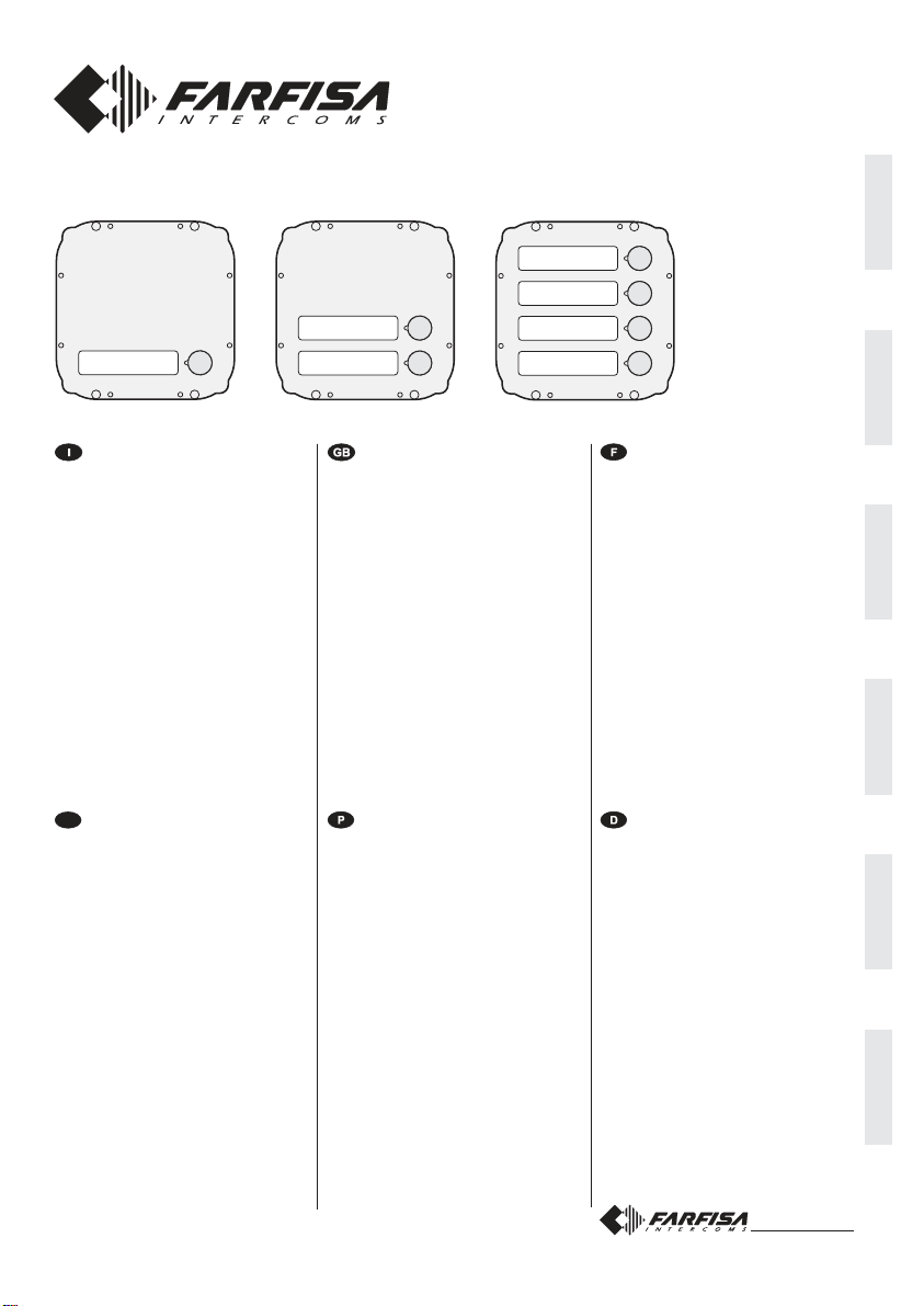
Art. CD2132MAS Art. CD2134MAS
Art. CD2131MAS
Mi 2318/1 24
DATA DI ACQUISTO - DATE OF PURCHASE - DATE D’ACHAT -
FECHA DE COMPRA - DATA DE COMPRA - EINKAUFSDATUM
TIMBRO E FIRMA DEL RIVENDITORE
DEALER’S NAME AND ADDRESS
NOM ET ADRESSE DU REVENDEUR
NOMBRE Y DIRECCION DEL DISTRIBUIDOR
CARIMBO E ASSINATURA DO REVENDEDOR
STÄMPEL DES HÄNDLERS
CERTIFICATO DI GARANZIA
(condizioni valide solo per il Territorio Italiano)
La garanzia ha la durata di 24 mesi dalla data di acquisto, accertata o
accertabile,evieneesercitatadallaDitta rivenditrice e, tramite questa,
dai Centri Assistenza Tecnica Autorizzati ACI Srl Farfisa Intercoms.
La garanzia deve essere esercitata, pena la decadenza, entro otto
giorni dalla scoperta del difetto.
LA GARANZIA NON E’ VALIDA SE NON DATATA E VIDIMATA CON
TIMBRO E FIRMA DEL RIVENDITORE ALL’ATTO DELL’ACQUI-
STO. CERTIFICATO UNICO ED INSOSTITUIBILE.
MATRICOLA - SET NUMBER - MATRICULE APPAREIL -
N° MATRICULA - N° DE MATRICULA - SERIENNUMMER
ACIsrlFarfisa Intercoms
Via E. Vanoni, 3 • 60027 Osimo (AN) • Italy
Tel:+39 071 7202038(r.a.) •Fax: +39071 7202037
Smaltireil dispositivosecondo quantoprescritto dallenorme perla tuteladell'ambiente.
Disposeofthedevicein accordancewith environmentalregulations.
Écouler le dispositif selon tout ce qu'a été prescrit par les règles pour la tutelle du milieu.
Eliminar el aparato según cuánto prescrito por las normas por la tutela del entorno.
Disponhadodispositivoconformeregulamentosambientais.
WerdenSiedas Gerätin ÜbereinstimmungmitUmweltregulierungenlos.
La ACI Srl Farfisa Intercoms si riserva il diritto di modificare in qualsiasi momento i prodotti qui illustrati.
ACI Srl Farfisa Intercoms reserves the right to modify the products illustrated at any time.
La ACI Srl Farfisa Intercoms se réserve le droit de modifier à tous moments les produits illustrés.
E’ reservada à ACI Srl Farfisa intercoms o direito de modificar a qualquer momento os produtos aqui ilustrados.
ACI Srl Farfisa intercoms se reserva el derecho de modificar en cualquier momento los productos ilustrados aquí
Änderungen vorbehalten.
Cod.52703581 Mi2318/1

ITALIANOENGLISHFRANÇAISESPAÑOLPORTUGUÊSDEUTSCH
ITALIANOENGLISHFRANÇAISESPAÑOLPORTUGUÊSDEUTSCH
Mi 2318/1 2
INSTALLAZIONE / INSTALLATION / INSTALLATION / INSTALACIÓN / INSTALAÇÃO / INSTALLATION
Mi 2318/1 23
Indica un errore durante la programmazione o che stà terminando
la conversazione.
Indicates an error during the programming phase or that the
conversation time is near to expire.
Indiqueuneerreurpendantlaprogrammationouquelaconversation
est presque terminée.
Señala un error durante la programación o que la conversación va
a terminar.
Indica um erro durante a programação ou que a conversação está
terminando.
Weist auf Fehler in der Programmierung oder Ablauf der
Gesprächsdauer hin.
Fine conversazione - End of conversation - Fin conversation - Fin de conversación - Fim conversação - Gesprächsende
Tabelladeitoni-Tonetable-Tableaudestonalités- Tablatonos-Tabeladossons-Tontabelle
Indica che l'interno non esiste o è occupato.
Indicatesthattheuseris busyornot existingorthattheline isbusy.
Indique que l’interne appelé n’existe pas ou qu’il est occupé.
Señala que la extensión buscada no existe o está ocupada.
Indica que o apartamento não existe ou está ocupado.
Interner Teilnehmer nicht bekannt oder besetzt.
Indicaunaerrataprogrammazionedeipulsantiopulsantenonusato
dal sistema.
Indicates that the push-buttons were wrongly programmed or not
used in the system.
Indiquequelesboutons-poussoirsontétéprogrammésdemanière
incorrecteouquelebouton-poussoirn’estpasutiliséparlesystème.
Señala una programación incorrecta de los pulsadores o pulsador
no utilizado por el sistema.
Indica uma programação errada dos botões ou botão não usado
pelo sistema.
Fehler bei der Programmierung der Tasten oder vom System nicht
benutzte Taste.
Occupato - Busy - Occupé - Ocupado - Ocupado - Besetzt
Dissuasione - Dissuasion - Dissuasion - Disuasión - Dissuasão - Dissuasion
Indicalacorrettaprogrammazioneodeffettuazionedellachiamata.
Indicates that the programming was executed correctly or that a
call is in progress.
Indique que la programmation est correcte ou que l’appel a été
effectué.
Señala la correcta programación o la realización de la llamada.
Indica a correta programação ou a efetuação da chamada.
Korrekt ausgeführte Programmierung oder Anruf.
Conferma - Acknowledge - Confirmation - Confirmación - Confirmação - Bestätigung
Indica che si è in modalità programmazione.
Indicates that the programming mode was accessed.
Indique que l’on est en mode de programmation.
Señala que estamos en el modo de programación.
Indica modalidade programação acionada.
System im Programmiermodus.
Programmazione - Programming - Programmation - Programación - Programação - Programmierung

ITALIANOENGLISHFRANÇAISESPAÑOLPORTUGUÊSDEUTSCH
ITALIANOENGLISHFRANÇAISESPAÑOLPORTUGUÊSDEUTSCH
Mi 2318/1 3
Morsetti
LP/LP fonia-dati-videoda e versogli interni
EC comando positivo per servizi ausiliari
EM comandonegativoperserviziausiliari
S1/S2 contattiaperturaserratura
Terminals
LP/LP audio-data-video to and from internal users
EC positive signal for exchanger
EM negative signal for exchanger
S1/S2 door opening contacts
Bornes
LP/LP phoniedonnées-vidéodepuis etverslesinternes
EC entréepositivecommandeéchangeur
EM entréenégativecommandeéchangeur
S1/S2 contactsouverturegâche
Bornes
LP/LP fonía-datos-vídeo desde o a los aparatos internos
EC entrada positiva mando intercambiador
EM entrada negativa mando intercambiador
S1/S2 contactos de abertura cerradura
Terminais
LP/LP fonia-dados-vídeodeepara os apartamentos
EC entradapositivocomandopermutador
EM entradanegativocomandopermutador
S1/S2 contatosaberturafechadura
Klemmens
LP/LP Sprechleitung-Datenleitung-Videoleitung zu
internen Teilnehmern
EC Plus-Eingang der Umschalteinrichtungssteuerung
EM Minus-EingangderUmschalteinrichtungssteuerung
S1/S2 Türschlossöffnungskontakte
all'impianto
to the installation
àl’installation
a la instalación
à instalação
zurAnlage
ponticello per la programmazione
jumper for programming
pontet pour la programmation
puente para programar
pontinho para a programação
Überbrückungsklemme zur Pro-
grammierung
allalinea
to the line
à la ligne
alalínea
para a linha
zurLinie
cavo per il collegamento ai successivi
modulipulsanti MA22SoMA24S
flat cable for the connection of additional
modules MA22S or MA24S
câble pour le branchement aux modules
MA22S ou MA24S successifs
cable para la conexión a los siguientes
módulosdepulsadoresMA22S ó MA24S
Cabo para a coligação aos módulos de
botões sucessivos MA22S ou MA24S
Kabel für den Anschluss an die
nachfolgenden Tastenmodule MA22S
oder MA24S
SW1 tasto di programmazione
SW1 programming button
SW1 touche de programmation
SW1 tecla de programación
SW1 tecla de programação
Programmierungstaste SW1
cavo per il collegamento al modulo audio/video
flat cable for connection to audio/video module
câble pour le branchement au module audio/vidéo
cable para la conexión al módulo de audio/vídeo
Cabo para a ligação ao módulo áudio/vídeo
Kabel für den Anschluss ans Audio-/Video-Modul
MS1-MS2 microinterruttori di programmazione
MS1-MS2 programming microswitches
MS1-MS2 micro-interrupteurs de programmation
MS1-MS2 micro-interruptores de programación
MS1-MS2 microinterruptor de programação
Programmierungsmikroschalter MS1-MS2
Morsettiere di connessione
Connection terminal boards
Borniers de connexion
Bornes de conexión
Terminais de conexão
Anschlußklemmenbretter
Mi 2318/1 22
occupato
busy
occupé
ocupado
ocupado
Besetzt
ingresso 2
door station 2
poste de rue 2
placa de calle 2
postoexterno1
Türstation 2
ingresso 1
door station 1
poste de rue 1
placa de calle 1
postoexterno1
Türstation 1
ITALIANOENGLISHFRANÇAISESPAÑOLPORTUGUÊSDEUTSCH
ITALIANOENGLISHFRANÇAISESPAÑOLPORTUGUÊSDEUTSCH
Mi 2318/1 4
postointernopiùlontano
farthest internal station
posteinterneleplus éloigné
Note
*La lunghezza totale dei cavi dal
derivatore ai posti interni non deve
superare i 300 metri (somma di tutte
letratte"E").
**Letterediriferimentoschematico(ve-
dere le pagine 8 e 9).
Notes
*The total lengh of cables from line
distributorstointernalstationsshould
not exceed 300m. (adding all the "E"
sections).
**Lettersforreferenceonthediagrams
(see pages 8 and 9).
postointernopiùlontano
farthest internal station
posteinterneleplus éloigné
Notes
*La longueur totale des câbles du
dérivateurauxpostesinternesnedoit
pasdépasser300mètres(sommede
touslestronçons“E”).
**Lettresderéférenceschématique(voir
pages 8 et 9).
Tipo e sezione dei condut-
tori
L'utilizzodelcavoart.2302,opportuna-
mentestudiatodallaACIFarfisa,èrac-
comandato per la realizzazione di im-
piantidigitaliDUOSystem.L'impiegodi
conduttoriinadeguatipotrebbenonga-
rantiretutteleprestazioniedinfluenzare
ilcorrettofunzionamentodelsistema.
Dati tecnici del cavo art. 2302
Numero dei conduttori 2 (rosso/nero)
Sezione dei conduttori 2x1mm²
Materialedeiconduttori rame stagnato
Passo di cordatura 40mm
Impedenza caratteristica 100Ω
Distanzemassimegarantiteconil
cavoart.2302
Type and cross-section of
conductors
Thecable art.2302 is the ideal solution
forwiringDUOdigitalsystems.Theuse
of inappropriate cables may have an
adverseeffectontheperformanceofthe
system.
Technical characteristics of cable
art.2302
Number of conductors 2 (red/black)
Cross-section of conductors 2x1mm²
Material of conductors tinned copper
Twistingpitch 40mm
Nominal impedance 100
Ω
Maximumdistancesguaranteedby
cableart.2302
Type et section des con-
ducteurs
L'usage du câble art.2302, opportuné-
ment étudié par l'ACI Farfisa, il est
recommandé pour la réalisation
d'installations digitaux DUO System.
L’utilisation de câbles différents peut
influencerlefonctionnementcorrectdu
système et n’en garantit pas les
performances.
Données techniques du câble art. 2302
Nombre de conducteurs 2(rouge/noir)
Section des conducteurs 2x1mm²
Matériau des conducteurs cuivre étamé
Pas de câblage 40mm
Impédance caractéristique 100Ω
Distancesmaximumgarantiesavec
lecâbleart.2302
art.2220
art.2273PRS210
art.2221
DV2420
DV2421
DV2424
CD2131÷34
DV2420
ML2002-KM8262
ML2002-KM8262
ML2002-KM8262
EX3262-EH9262
EX3262-EH9262
EX3262-EH9262
DV2420
50m.
200m.***
200m.***
50m.
200m.***
30m.**
A
B
C
D
F
E
TD2100MA
CD2131÷34
TD2100MA
CD2131÷34
TD2100MA
*
Mi 2318/1 21
E
FUNCIONAMIENTO
Averiguar que las conexiones de la
instalaciónsehanhechocorrectamen-
te. Poner en función la instalación
conectando el alimentador a la red.
Para realizar la llamada presionar el
pulsadordelusuariodeseado.Elenvío
será confirmado por un tono de libre si
la línea es disponible o de ocupado si
la línea no es disponible (véase tabla
detonos).
El aparato llamado suena solo una
vez;siduranteestafasesepresionade
nuevo el mismo pulsador el aparato
sonará nuevamente.
Al levantar el auricular, el usuario
llamado interrumpe la llamada y
habilita la conversación con la placa
de calle durante unos 90 segundos.
Faltando 10 segundos al término de la
conversación se oye un tono de fin de
conversación; hay que presionar de
nuevo el pulsador del usuario llamado
paracontinuarlaconversacióndurante
90 segundos más.
Para accionar la apertura de la cerra-
dura, presionar el pulsador . El
tiempodehabilitaciónesde3segundos
(ode6segundossisehaprogramado).
Tras colgar el auricular la instalación
vuelve al estado de reposo.
En las instalaciones que tienen 2 o
más placas de calle, si se realiza una
llamada desde una placa de calle, las
demás se inhabilitan y se oye el tono
deocupado(LEDrojoparpadeandoen
el módulo de audio o de audio-video).
Hay que esperar que la línea se libere
para realizar una nueva llamada.
FUNCIONAMENTO
Verificarque as ligaçõesda instalação
estejam efetuadas corretamente.
Colocaremfunçãoainstalação,ligando
o alimentador à rede.
Para efetuar a chamada, pressionar o
botão do usuário desejado. A
confirmação do envio será obtida por
umsomdedesocupadosealinhaestiver
disponíveloudeocupadosealinhanão
estiverdisponível(vejatabeladossons).
Oaparelhochamadotocaapenasuma
vez;senestafasepressionarmosainda
o mesmo botão, o aparelho toca
novamente.
Ousuáriochamado,aolevantaromicro-
telefone,interrompeachamada,habilita
a conversação com o exterior por um
tempo de 90 segundos.
Faltando 10 segundos para o final da
conversação, será ouvido um som de
fim de conversação; pressionar
novamenteobotãodousuáriochamado
paracontinuaraconversaçãopormais
90segundos.
Paraaccionaraaberturadafechadura,
pressionar o botão . A duração da
habilitação é de 3 segundos (ou de 6
segundos se tiver sido programada
diversamente).
Recolocando o micro-telefone, a
instalaçãovoltaàposiçãoemrepouso.
Eminstalaçõescom2oumaispostos
externos,aoefetuarachamadadeum
local, as outras se desabilitam com a
sinalizaçãodeocupado(Ledvermelho
lampejante no módulo áudio ou áudio-
vídeo). Aguardar que a linha seja
liberadapara efetuar achamada.
BETRIEB
Kontrollieren,obdieVerbindungender
Anlage richtig hergestellt wurden.
Anlage durch Anschluss des Netz-
geräts in Betrieb nehmen.
Zur Ausführung des Rufes Taste des
gewünschten Teilnehmers drücken.
Nach Ausführung des Rufes ist ein
Freizeichenzuhören,wenndieLeitung
frei ist oder ein Besetztzeichen, wenn
diese nicht frei ist (siehe Tontabelle).
Der angerufene Apparat klingelt nur
einmal;wenn in dieserPhase dieselbe
Taste nochmals gedrückt wird, klingelt
der Apparat erneut.
DerangerufeneTeilnehmerermöglicht
durch Abheben des Hörers ein
Gespräch mit dem externen Anrufer
von 90 Sekunden.
10 Sekunden vor Gesprächsende ist
einentsprechenderTonzuhören;wenn
dasGesprächfürweitere90Sekunden
fortgesetzt werden soll, ist erneut die
Taste des angerufenen Teilnehmers
zudrücken.
Zur Betätigung des Türschlosses ist
die Sprechgerättaste zu drücken.
Die Aktivierungsdauer beträgt 3
Sekunden (oder 6 Sekunden bei
anderer Programmierung).
Durch Auflegen des Hörers kehrt die
Anlage in die Ruhestellung zurück.
In Anlagen mit 2 oder mehr
TürstationenwerdenbeiRufvoneiner
Station aus die anderen Türstationen
deaktiviert, wobei die Besetztanzeige
erscheint (rote LED blinkt auf dem
Audio- oder Audio-Video-Modul).
ITALIANOENGLISHFRANÇAISESPAÑOLPORTUGUÊSDEUTSCH
ITALIANOENGLISHFRANÇAISESPAÑOLPORTUGUÊSDEUTSCH
Mi 2318/1 6
Serratura elettrica
Comemostratoneisuccessivischemi
installativi,laserraturaelettricapuòes-
sereazionatadallostessoalimentato-
re che alimenta il posto esterno, ma
affinchèilsistemafunzionicorrettamen-
telaserraturaelettricadeveesseredel
tipo12Vca/1A max. Durantel'aziona-
mentodellaserraturailsegnalevideo
puòesseredisturbato.Perevitareque-
sto inconveniente o per azionare ser-
rature con caratteristiche differenti si
suggeriscediutilizzareunalimentato-
resupplementarecomeriportatonello
schemaseguente.
IMPORTANTE
Al fine di ottemperare alla Direttiva Euro-
pea sulla Compatibilità Elettromagnetica
eperaumentarel’affidabilitàdelprodotto,
ènecessarioconnettereun dispositivo di
soppressione dei disturbi quando si co-
manda un carico induttivo, per esempio
unaserraturaelettrica(SE).Isoppressori
inclusi(transil)devonoessereconnessiil
piùvicinopossibilealcarico(teoricamen-
te sui terminali dello stesso).
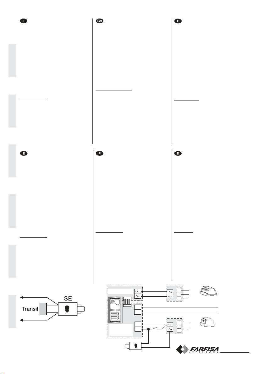
Electricdoorlock
As shown in the installation diagrams
the electric lock can be operated using
the same power supply which powers
thedoorstation,butforacorrectopera-
tion the electric lock must be a 12VAC/
1A max type. During the release of the
electric lock the video signal can be
disturbed. To avoid this inconvenient
or to operate a powerful electric lock it
wouldbeadvisabletouseanextrapower
supply as reported in the following dia-
gram.
VERY IMPORTANT
TocomplywiththeEuropeanStandardson
Electromagnetic Compatibility and to in-
crease the reliability of the product, it is
necessary to connect a suppression de-
vice when switching inductive loads i.e.
electric releases and electric locks (SE).
Theenclosedsuppressiondevices(transil)
mustbeconnectedasclose as possible to
the loads (ideally across the terminals.
See figure).
Gâche électrique
Tel qu’illustré dans les schémas
d’installationsuivants,lagâcheélectrique
peut être activée par la même
alimentationquialimentelepostederue
mais, pour que le système fonctionne
correctement, la gâche électrique doit
êtredutype12Vca/1Amax.ilsepeutque
le signal vidéo soit dérangé lors de
l’activation de la gâche. Pour éviter cet
inconvénientoupouractiverdesgâches
ayantdescaractéristiquesdifférents,on
suggère d’utiliser une alimentation
supplémentaire, tel qu’illustré dans le
schémasuivant.
IMPORTANT
Conformément à la Directive Européenne
sur la Compatibilité Electromagnétique et
pour augmenter la fiabilité du produit, il faut
connecter un dispositif de suppression des
dérangements quand on commande une
charge inductive, par exemple une serrure
électrique (SE). Les suppresseurs inclus
(transil) doivent être connectés le plus près
possible de la charge (théoriquement sur
les terminaux de la charge même).
Cerraduraeléctrica
Como se ve en los siguientes
diagramasdeinstalación,lacerradura
eléctrica se puede accionar por el
mismo alimentador que alimenta la
placa de calle, pero, para que el
sistema funcione correctamente, la
cerradura eléctrica debe ser del tipo
12Vca/1A max. Durante el funciona-
miento de la cerradura la señal de
vídeo puede ser perturbada. Para
evitarelinconvenienteoparaaccionar
cerraduras con diferentes caracte-
rísticas, se sugiere emplear un
alimentadoradicional,comoindicado
en el diagrama siguiente.
IMPORTANTE
Para el fin de obedecer a la Directiva
EuropeasobrelaCompatibilidadElectro-
magnética, y también para mejorar la
seguridad del producto es necesario co-
nectar un dispositivo de supresión de
estorbosalmandodeunacargainductiva,
porejemplounacerraduraeléctrica(SE).
Los supresores incluidos (transil) se de-
ben conectar lo más cerca posible al
mando (en teoría, directamente en los
terminales del mismo).
Fechadura elétrica
Como ilustrado nos esquemas de
instalação sucessivos, a fechadura
elétricapodeseracionadapelomesmo
alimentadorquealimentaolocalexterno,
mas, a fim de que o sistema funcione
corretamente,afechaduraelétricadeve
ser do tipo 12Vca/1A max. Durante o
funcionamento da fechadura, o sinal
vídeo pode sofrer interferências. Para
evitaresteinconvenienteouparaacionar
fechaduras com características
diferentes, sugerimos a utilização de
umalimentadorsuplementardeacordo
comadescriçãodoseguinteesquema.
IMPORTANTE
Com a finalidade de respeitar a Diretiva
Européia sobre a Compatibilidade Eletro-
magnéticaeparaaumentaracredibilidade
do produto, é necessário conectar um dis-
positivodesupressãodosdistúrbiosquan-
dosecomandaumcarregamentoindutivo,
por exemplo uma fechadura elétrica (SE).
Os supressores incluídos (transil) devem
ser conectados o mais próximo possível
do carregamento (teoricamente, directa-
mente sobre os terminais do mesmo).
Elektrotürschloss
Wie in den folgenden Schaltplänen
gezeigtwird,kanndasElektrotürschloss
mit dem für die Türstation verwendeten
Netzgerätversorgtwerden;zurkorrekten
Funktion des Systems muss das
Elektrotürschloss allerdings mit max.
12VWs/1A betrieben werden. Während
der Betätigung des Türschlosses kann
u.U. das Videosignal gestört sein. Zur
Vermeidung dieser Störung oder zur
Betätigung von Türschlössern mit
anderen Merkmalen empfiehlt es sich,
wie nachstehend erläutert, ein
Zusatznetzgerätzuverwenden.
WICHTIG!
Gemäß den Europäischen Richtlinien zur
elektromagnetischenKompatibilitätundzur
Erhöhungder ZuverlässigkeitdesProdukts
muß bei induktiver Belastung, z. B. bei Be-
tätigung eines Elektrotürschlosses (SE),
eineEntstörvorrichtungangeschlossenwer-
den. Die mitgelieferten Entstörer (Transil)
müssen so nahe wie möglich an der Last
(theoretisch direkt an den End-Verschlüs-
sen derselben) angeschlossen werden.
PA
SE
PRS210
VD2120CMAS
CD2131MAS
CD2134MAS
CD2132MAS
LP
LP
2220
230V
230V
127V
127V
0
0
S1
S2
Mi 2318/1 19
ITALIANOENGLISHFRANÇAISESPAÑOLPORTUGUÊSDEUTSCH
ITALIANOENGLISHFRANÇAISESPAÑOLPORTUGUÊSDEUTSCH
Mi 2318/1 7
chiusura / termination / fermeture
cierre / fechadura / Schließung
J1 = 1-2 = 47Ω
3-4 = 70Ω
4-5 = 100Ω
2 POSTI INTERNI IN PARALLELO
2 APARATOS INTERNOS EN
PARALELO
Nei riquadri vi sono gli articoli aggiuntivi
agli schemi base delle pagine 8 e 9.
En los cuadros se indican los artículos
adicionales a los diagramas básicos de
las páginas 8 y 9.
3 POSTI INTERNI IN PARALLELO
3 APARATOS INTERNOS EN
PARALELO
Inthe dashedboxes areshown theitems
to add the basic diagrams reported at
pages 8 and 9.
Osquadrosilustramosartigosadicionais
aos esquemas-base das páginas 8 e 9.
2 POSTES INTERNES EN PARALLELE
2 INTERNE GERÄTE PARALLEL
Voir dans les cases les articles supplémen-
tairesauxschémasdebasedespages8et9.
In den Kästen sind die gegenüber den
BasisschaltplänenaufSeite8und9zusätzlich
zu verwendenden Artikel aufgeführt.
3 POSTES INTERNES EN PARALLELE
3 INTERNE GERÄTE PARALLEL
2 PARALLEL INTERNAL STATIONS
2 POSTOS INTERNOS EM
PARALELOS
3 PARALLEL INTERNAL STATIONS
3 POSTOS INTERNOS EM
PARALELOS
DV2421P
DV2421P
LM
LM
A1
GN
LM
LM
A1
GN
LM
LM
LI
LI
LO LO
J1
54321
LI LI
J1
J1
J1
5
5
5
4
4
4
3
3
3
2
2
2
1
1
1
ML2002+ML2083
EH9262+9083
EX3262+WB3262
KM8262+WB8262
EX362
KM862
E
ML2002+ML2083
EH9262+9083
EX3262+WB3262
KM8262+WB8262
EX362
KM862
DV2421P
DV2421P
LM
LM
A1
GN
LM
LM
A1
GN
LM
LM
A1
GN
LM
LM
LI
LI
LO LO
J1
54321
LI LI
J1
J1
J1
5
5
5
4
4
4
3
3
3
2
2
2
1
1
1
ML2002+ML2083
EH9262+9083
EX3262+WB3262
KM8262+WB8262
EX362
KM862
ML2002+ML2083
EH9262+9083
EX3262+WB3262
EX362
KM8262+WB8262
KM862
ML2002+ML2083
EH9262+9083
EX3262+WB3262
KM8262+WB8262
EX362
KM862
E
chiusura / termination
fermeture / cierre
fechadura / Schließung
J1 = 1-2 = 47Ω
3-4 = 70Ω
4-5 = 100Ω
Mi 2318/1 18
ITALIANOENGLISHFRANÇAISESPAÑOLPORTUGUÊSDEUTSCH
ITALIANOENGLISHFRANÇAISESPAÑOLPORTUGUÊSDEUTSCH
Mi 2318/1 8
J1 = 1-2 chiusura/termination/fermeture47Ω
cierre / fechadura / Schließung
3-4 chiusura/termination/fermeture70Ω
cierre / fechadura / Schließung
4-5 chiusura/termination/fermeture100Ω
cierre / fechadura / Schließung
Si51VM/2
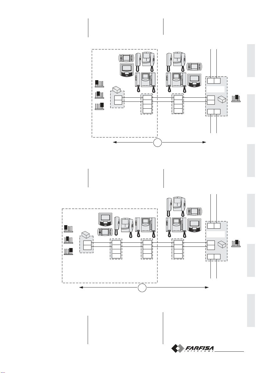
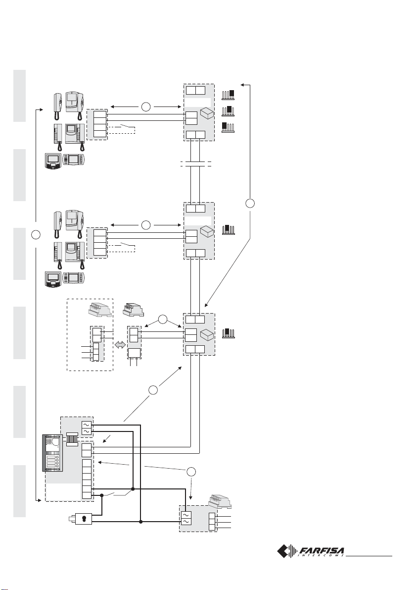
IMPIANTO MISTO CITOFONICO-VIDEOCITOFONICO COLLEGATO AD UN POSTO ESTERNO
MIXED INTERCOM-VIDEOINTERCOM SYSTEM CONNECTED TO ONE EXTERNAL DOOR STATION
INSTALLATION MIXTE INTERPHONIQUE-VIDÉOPHONIQUE BRANCHÉE À UN POSTE DE RUE
SISTEMA MIXTO DE PORTERO-VIDEOPORTERO CONECTADO A UNA PLACA DE CALLE
INSTALAÇÃO MISTA DE TELEFONES PORTEIRO-VÍDEO-PORTEIRO LIGADO A UM POSTO EXTERNO
VIDEOSPRECHANLAGE MIT GEMISCHTEN VIDEOHAUSTELEFONE / HAUSTELEFONE
PA = Pulsanteapriporta(opzionale)
Doorreleasepush-button(optional)
Bouton-poussoirouvreporte(optionnel)
Pulsadorabrepuerta(opcional)
Botãoparaabriraporta(opcional)
ZusätzlicheTüröffnertaste(Ergänzung)
SE = Serraturaelettrica(12Vca-1Amax.)
Electric door lock (12VAC-1A max)
Gâcheélectrique(12Vca-1Amax)
Cerraduraeléctrica(12Vca-1Amáx.)
Fechaduraeléctrica(12Vca-1Amax)
Türöffner(12Vac-1Amax)
FP= Pulsante chiamata dipiano (opzionale)
Floorcall push-button (optional)
Bouton-poussoirdepalier(optionnel)
Pulsadordepiso(opcional)
Botãodepatamar(opcional)
Etagenruftaste(Ergänzung)
DV2420
D
J1
12345
J1
12345
LM
LM
PA
SE
2220S
2220
230V
230V
127V
127V
0
0
DV2421P
DV2421P
LM
LM
LM
LM
LI LI
LO
LO
LO
LO
LI LI
LM
LM
A1
GN
LM
LM
A1
GN
FP
FP
A
B
E
E
C
ML2002+ML2083
EH9262+9083
EX3262+WB3262
KM8262+WB8262
EX362
KM862
ML2002+ML2083
EH9262+9083
EX3262+WB3262
KM8262+WB8262
EX362
KM862
LO LO
LI LI
J1
12345
J1
12345
J1
12345
2221S2221ML
LP
LP
LP
LP
PRI
110V÷240VAC
VD2120CMAS
LP
LP
P1
P1
EC
EM
S1
S2
F
CD2131MAS
CD2132MAS
CD2134MAS
J1 = 2-3 linea aperta / open line / ligne ouverte
líneaabierta /linhaaberta/offeneLinie
J1 = 2-3 linea aperta / open line / ligne ouverte
líneaabierta /linhaaberta/offeneLinie
Mi 2318/1 17
Tabella 3
Corrispondenza tra i codici e la posi-
zione dei microinterruttori di MS1 e
MS2.
Table 3
Cross-reference between codes and
microswitches position of MS1 and
MS2.
Tableau2
Tableau de correspondance entre les
codes et la position des micro-
interrupteurs de MS1 et MS2.
Tabla de correspondencia entre los
códigos y la posición de los micro-
interruptores de MS1 y MS2.
Tabela de correspondência entre
os códigos e a posição dos
microinterruptores de MS1 e MS2.
Tabelle der Übereinstimmung zwischen
Codes und Mikroschalterposition bei
MS1 und MS2
ITALIANOENGLISHFRANÇAISESPAÑOLPORTUGUÊSDEUTSCH
ITALIANOENGLISHFRANÇAISESPAÑOLPORTUGUÊSDEUTSCH
Mi 2318/1 9
PA
SE
230V
127V
0
DV2421P
DV2421P
P1
P1
EC
EM
S1
S2
LM
LM
A1
GN
LM
LM
LM
LM
L2 L2
LO
LO
LO
LO
230V
127V
0
LI LI
LM
LM
A1
GN FP
FP
C
PA
SE
230V
127V
0
“232” “231”
LP
LP
P1
P1
EC
EM
S1
S2
E
E
AA
F
EC
EM
S1
S2
2273
LP
LP
PRS210
B
SW2
4321
ON
ON
LP LP
J1
12345
J1
12345
J1
12345
J1
12345
LI LI
L1 L1
2220S
2220
VD2120CMAS
2220S
2220
ML2002+ML2083
EH9262+9083
EX3262+WB3262
KM8262+WB8262
EX362
KM862
ML2002+ML2083
EH9262+9083
EX3262+WB3262
KM8262+WB8262
EX362
KM862
VD2120CMAS
DV2420
D
J1
12345
LM
LM
230V
127V
0
LO LO
LI LI
2221S2221ML
LP
LP
LP
LP
PRI
110V÷240VAC
CD2131MAS
CD2132MAS
CD2134MAS
CD2131MAS
CD2132MAS
CD2134MAS
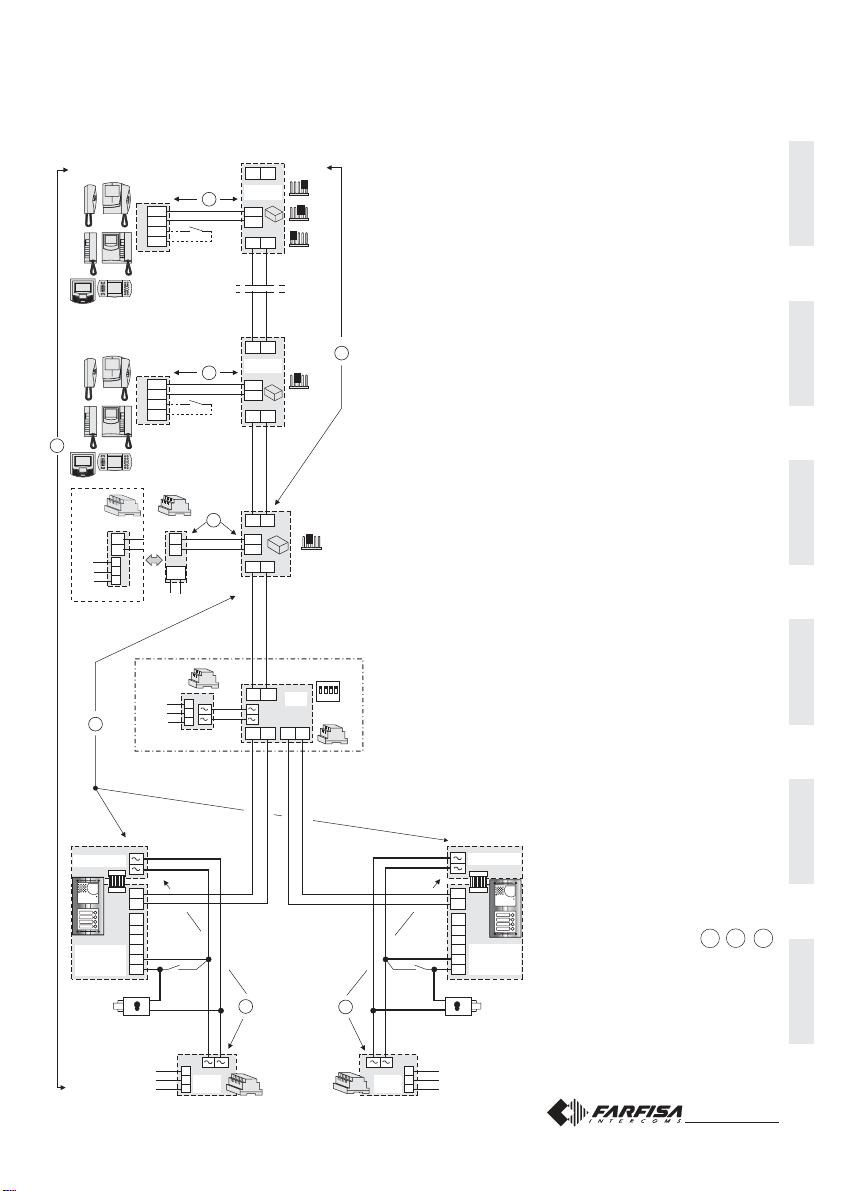
IMPIANTO VIDEOCITOFONICO COLLEGATO A DUE POSTI ESTERNI
VIDEOINTERCOM SYSTEM CONNECTED TO TWO EXTERNAL DOOR STATIONS
INSTALLATION VIDÉOPHONIQUE BRANCHÉE À DEUX POSTES DE RUE
SISTEMA DE VIDEOPORTERO CONECTADO A DOS PLACAS DE CALLE
INSTALAÇÃO DE VÍDEO-PORTEIRO LIGADO A DOIS POSTOS EXTERNOS
VIDEOSPRECHANLAGE MIT ZWEI UMSCHALTBAREN VIDEOTÜRSTATIONEN
Nota/Note/Nota/Hinweis.B = B1 + B2
SE = Serraturaelettrica(12Vca-1Amax.)
Electric door lock (12VAC-1A max)
Gâcheélectrique(12Vca-1Amax)
Cerraduraeléctrica(12Vca-1Amáx.)
Fechaduraeléctrica(12Vca-1Amax)
Türöffner(12Vac-1Amax)
PA = Pulsanteapriporta(opzionale)
Doorreleasepush-button(optional)
Bouton-poussoirouvreporte(optionnel)
Pulsadorabrepuerta(opcional)
Botãoparaabriraporta(opcional)
ZusätzlicheTüröffnertaste(Ergänzung)
FP= Pulsante chiamata dipiano (opzionale)
Floorcall push-button (optional)
Bouton-poussoirdepalier(optionnel)
Pulsadordepiso(opcional)
Botãodepatamar(opcional)
Etagenruftaste(Ergänzung)
J1 = 1-2 chiusura / termination / fermeture 47Ω
cierre / fechadura / Schließung
3-4 chiusura / termination / fermeture 70Ω
cierre / fechadura / Schließung
4-5 chiusura / termination / fermeture 100Ω
cierre / fechadura / Schließung
J1 = 2-3 linea aperta / open line / ligne ouverte
línea abierta / linha aberta / offene Linie
Si52VM/1
Mi 2318/1 16
ON
tempodeacionamentodafechadura;6segundos
Türöffnungszeit; 6 Sekunden
chamadadeapartamentohabilitada
Kontrolleinschaltung freigegeben
NÃO USADO: deixar na posição OFF
geradordesonsnopostoexterno;NÃOhabilitado*
FreizeichenanderTürstationNICHTeinschalten*
OFF
tempode acionamento dafechadura; 3 seg.
Türöffnungszeit; 3 Sekunden
chamadade apartamento NÃOhabilitada *
Kontrolleinschaltung NICHT freigegeben*
geradordesonsnoposto externo; habilitado
Freizeichen an der Türstation einschalten
1
2
3
4
MS1 MS2
1A
2A
1B
2B
1C
AA
Tabela 1 - Tabelle 1
Códigos de seleção da programação
Programmierkennungen
Endereçoassociadoaoprimeirobotãodechamada.Códigosde1a200(vejatabela3).
Die Rufnummer der ersten Taste. Werte von 1 zu 200 (siehe Tabelle 3).
Endereço associado ao último botão de chamada. Códigos de 1 a 200 (veja tabela 3).
Die letzte Rufnummer. Werte von 1 zu 200 (siehe Tabelle 3).
Endereço do posto externo. Códigos de 231 a 250 (veja tabela 3).
Rufnummer der Türstation. Werte von 231 zu 250 (siehe Tabelle 3).
Programações de sistema (veja tabela 2).
Funktionsvarianten (siehe Tabelle 2).
Presençacentraldeportaria.Inseriroendereço201 seabotoneiraenviarchamadasa
1 ou mais centrais principais ou endereço 210 se a botoneira enviar chamadas a 1 ou
maiscentraissecundárias(vejatabela3).
Anwesenheit von Pförtnerzentrale. Die Adresse 201 eingeben, wenn die Türstation
Anrufe an 1 oder mehrere primären Pförtnerzentralen sendet, oder die Adresse 210,
wenn die Türstation Anrufe an 1 oder mehrere sekundären Pförtnerzentralen sendet.
Retorno à programação de fábrica. Código 85 (veja tabela 3).
Laden der ab Werk eingestellten Grunddaten. Wert 85 (siehe Tabelle 3).
MS1 MS2
1A
2A
MS1 MS2
MS1 MS2
1B
2B
MS1
ON
1234
MS2
1C
Tabela 2 - Tabelle 2
Programações de sistema (código 2B) - Funktionsvarianten (Code 2B)
Posição microinterruptores de MS1 - MS2 DIP-Schalter-Position bei MS1 - MS2
Microinterruptores
DIP-Schalter
MS1
MS2 Duranteestasprogramaçõestodososmicro-interruptoresdeMS2têmquepermaneceremposição
OFF
Bei dieser Programmierungen müssen alle DIP-Schalter von MS2 in Position OFF bleiben
Endereço ou função para fins de programação
Programmierfunktion
MS1 MS2
AA
* Aohabilitarestafunçãoépossível,decadaapartamentoe
porintermédiodapressãodobotão ,conversarcomum
postoexterno(nocasodeváriospostosexternosparalelos,
pode-seentraremcomunicaçãocomoúltimopostoexterno
que tenha efetuado a chamada) e, pressionando o botão
accionara fechadura.
* Bei Aktivierung dieser Funktion kann sich jedes Video-
haustelefon durch Drücken der Taste eine Verbindung
zur Türstation herstellen (bei mehreren parallel geschalte-
ten Türstationen erfolgt die Verbindung zur Türstation die
als letzte einen Ruf ausgesendet hat) und durch Drücken
der Taste den Türöffner aktivieren.
OHNE FUNKTION: auf Position OFF stehen lassen
ITALIANOENGLISHFRANÇAISESPAÑOLPORTUGUÊSDEUTSCH
ITALIANOENGLISHFRANÇAISESPAÑOLPORTUGUÊSDEUTSCH
Mi 2318/1 10
L2
L2
L2
L2
230V
127V
0
2273
2273
PRS210
B
SW2
SW2
4321
ON
4321
ON
ON
OFF
LP LP
LP LP
L1
L1
“a“ “a““b“
L1 L1
(*)
PA
SE
230V
127V
0
PA
SE
230V
127V
0
“231”
AA
2220S
2220
2220S
2220
P1
P1
EC
EM
S1
S2
LP
LP
VD2120CMAS
CD2131MAS
CD2132MAS
CD2134MAS
“232”
LP
LP
P1
P1
EC
EM
S1
S2
EC
EM
S1
S2
VD2120CMAS
CD2131MAS
CD2132MAS
CD2134MAS
DV2421P DV2421P
DV2421P DV2421P
LM
LM
A1
GN
LM
LM
A1
GN
LM
LM
LM
LM
LM
LM
LM
LM
LO LO
LO LO
LO LO
LO LO
LI LILI LI
LM
LM
A1
GN
LM
LM
A1
GN
FP FP
FP FP
C
E E
E E
F F
J1
12345
J1
12345
J1
12345
J1
12345
J1
12345
J1
12345
J1
12345
J1
12345
LI LILI LI
ML2002+ML2083
EH9262+9083
EX3262+WB3262
KM8262+WB8262
EX362
KM862
ML2002+ML2083
EH9262+9083
EX3262+WB3262
KM8262+WB8262
EX362
KM862
ML2002+ML2083
EH9262+9083
EX3262+WB3262
KM8262+WB8262
EX362
KM862
ML2002+ML2083
EH9262+9083
EX3262+WB3262
KM8262+WB8262
EX362
KM862
DV2420 DV2420
D D
J1
12345
J1
12345
LM
LM
LM
LM
230V 230V
127V 127V
00
LO LOLO LO
LI LILI LI
2221S 2221S2221ML 2221ML
LP
LP
LP
LP
LP
LP
LP
LP
PRI PRI
110V÷240VAC 110V÷240VAC
Nota/Note/Note.B = B1 + B2
Nota/Anmerkung F = F1 + F2
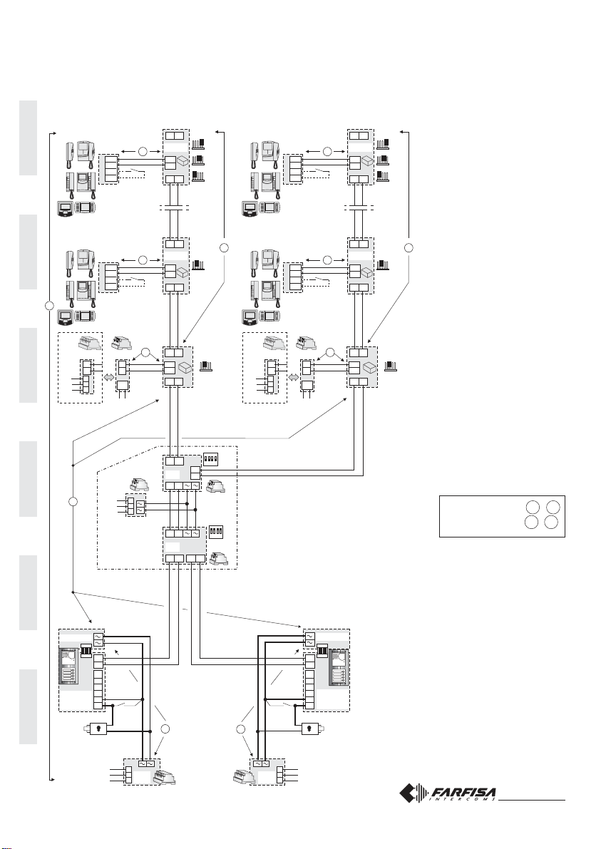
IMPIANTO VIDEOCITOFONICO COLLEGATO A DUE POSTI ESTERNI E DUE MONTANTI VIDEO
VIDEOINTERCOM SYSTEM CONNECTED TO TWO EXTERNAL DOOR STATIONS AND TWO VIDEO RISERS
INSTALLATION VIDÉOPHONIQUE BRANCHÉE À DEUX POSTES DE RUE ET DEUX COLONNES VIDEO
SISTEMA DE VIDEOPORTERO CONECTADO A DOS PLACAS DE CALLE Y DOS COLUMNAS VIDEO
INSTALAÇÃO DE VÍDEO-PORTEIRO LIGADO A DOIS POSTOS EXTERNOS E DOIS COLUNAS VIDEO
VIDEOSPRECHANLAGE MIT 2 UMSCHALTBAREN VIDEOTÜRSTATIONEN UND 2 VIDEOHAUTSTRÄNGE
J1 = 2-3
linea aperta / open line/ ligne ouverte
línea abierta / linha aberta / offene Linie
Si 52VM/2
PA = Pulsanteapriporta(opzionale)
Doorreleasepush-button(optional)
Bouton-poussoirouvreporte(optionnel)
Pulsadorabrepuerta(opcional)
Botãoparaabriraporta(opcional)
ZusätzlicheTüröffnertaste(Ergänzung)
SE = Serraturaelettrica(12Vca-1Amax.)
Electric door lock (12VAC-1A max)
Gâcheélectrique(12Vca-1Amax)
Cerraduraeléctrica(12Vca-1Amáx.)
Fechaduraeléctrica(12Vca-1Amax)
Türöffner(12Vac-1Amax)
FP= Pulsante chiamata dipiano (opzionale)
Floorcall push-button (optional)
Bouton-poussoirdepalier(optionnel)
Pulsadordepiso(opcional)
Botãodepatamar(opcional)
Etagenruftaste(Ergänzung)
J1 = 2-3
linea aperta / open line/ ligne ouverte
línea abierta / linha aberta / offene Linie
J1 =
1-2 chiusura / termination / fermeture 47Ω
cierre / fechadura / Schließung
3-4 chiusura / termination / fermeture 70Ω
cierre / fechadura / Schließung
4-5 chiusura/termination/fermeture100Ω
cierre / fechadura / Schließung
Mi 2318/1 15
PROGRAMAÇÕES
Para efetuar as programações, é necessário efetuar as
seguintesfases:
1) entrar na modalidade programação
2) inserir o código da programação que se pretende
efetuar
3) inserir o endereço solicitado ou o código da função
desejada
4) sair da programação
Notas
- E' possível, a qualquer momento, sair da fase de
programação, seguindo as indicações do parágrafo 4.
- Para efetuar outras programações é suficiente repetir as
fases 2 e 3 várias vezes.
1) ENTRADANAMODALIDADEPROGRAMAÇÃO
Deslocar o pontinho J1,colocado no
retrodabotoneira,daposição2-3a1-
2; será ouvido o som de programa-
ção.
Posições pontinho J1
1-2 = modalidade programação
2-3=modalidadefuncionamento
2) INSERÇÃOCÓDIGOSDESELEÇÃODAPROGRA-
MA-ÇÃO
Nosmicro-interruptoresMS1 eMS2,progra-
marocódigodaprogramaçãoquesepreten-
de efetuar como ilustrado na tabela 1 (códi-
gos 1A,2A,1B,2B,1C e AA).
Pressionar a tecla de programação SW.
3) PROGRAMAÇÃO ENDEREÇO OU CÓDIGO FUN-
ÇÃO
Nosmicro-interruptoresMS1eMS2,programaroendere-
çodesejado,usandoacorrespondênciailustradanatabe-
la3.Paraasprogramaçõesdesistema(código2B)videa
tabela2.
Pressionar a tecla de programação SW.
- Repetirváriasvezesasfases2e3atécompletaraprogra-
mação do decodificador.
- AcadapressãodateclaSWumsomdeconfirmaçãooude
erroindicaráaemissãodeumcódigocorretoouerrado;no
segundo caso será necessário reinserir o código exato.
4) SAÍDADAMODALIDADEPROGRAMAÇÃO
Parasairdaprogramação,énecessárioposicionartodosos
microinterruptores de MS1 e MS2 em OFF, deslocando o
pontinho J1 da posição 1-2 a 2-3.
PROGRAMMIERUNG
Zur Programmierung ist wie folgt vorzugehen:
1) Programmiermodusaktivieren
2) Kennung für die gewünschte Programmierung
eingeben
3) Rufnummer oder gewünschte Funktion eingeben
4) Programmiermodusdeaktivieren
Hinweis
- DerProgrammiermodus kann jederzeit wie in Abschnitt4
beschrieben deaktiviert werden.
- Für weitere Programmierungen sind jeweils die Schritte 2
und 3 zu wiederholen.
1) PROGRAMMIERMODUSAKITIVIEREN
Brückenstecker J1 auf der Rückseite
der Steuereinheit von Position 2-3 auf
Position 1-2 umstecken, ein
Programmierungston ist zu hören.
Positionen des Brückensteckers J1
1-2 = Programmierungsmodus
2-3 = Normaler Betrieb
2) EINGABEDERPROGRAMMIERKENNUNG
Gewünschte Kennung auf den DIP-
Schaltern MS1 und MS2 wie in der Ta-
belle 1 angegeben eingeben (Kennun-
gen 1A, 2A, 1B, 2B,1C und AA).
Programmiertaste SW betätigen.
3)PROGRAMMIERUNGDER RUFNUMMERNODER
FUNKTIONEN
GewünschteRufnummeraufdenDIP-SchalternMS1und
MS2wieinderTabelle3angegebeneingeben.Bezüglich
der Funktionsvarianten (Code 2B) siehe Tabelle 2.
Programmierungstaste SW drücken.
- Schritte 2 und 3 wiederholen, bis die Steuereinheit voll-
ständig programmiert ist.
- Bei jedem Drücken der Taste SW informiert ein
Bestätigungs- oder Fehlerton dem Benutzer an, ob der
eingegebeneWert richtigoderfalschist.BbeiFehleingabe
ist der richtige Wert einzugeben.
4) PROGRAMMIERMODUSDEAKTIVIEREN
Um den Programmiermodus zu deaktiviern, sind die DIP-
Schalter MS1 und MS2 auf OFF zu stellen und der
BrückensteckerJ1istvonPosition1-2wieder auf Position
2-3umzustecken.
MS1 MS2
LP
LP
J1 J1
1-2 2-3
J1
112233

ITALIANOENGLISHFRANÇAISESPAÑOLPORTUGUÊSDEUTSCH
ITALIANOENGLISHFRANÇAISESPAÑOLPORTUGUÊSDEUTSCH
Mi 2318/1 11
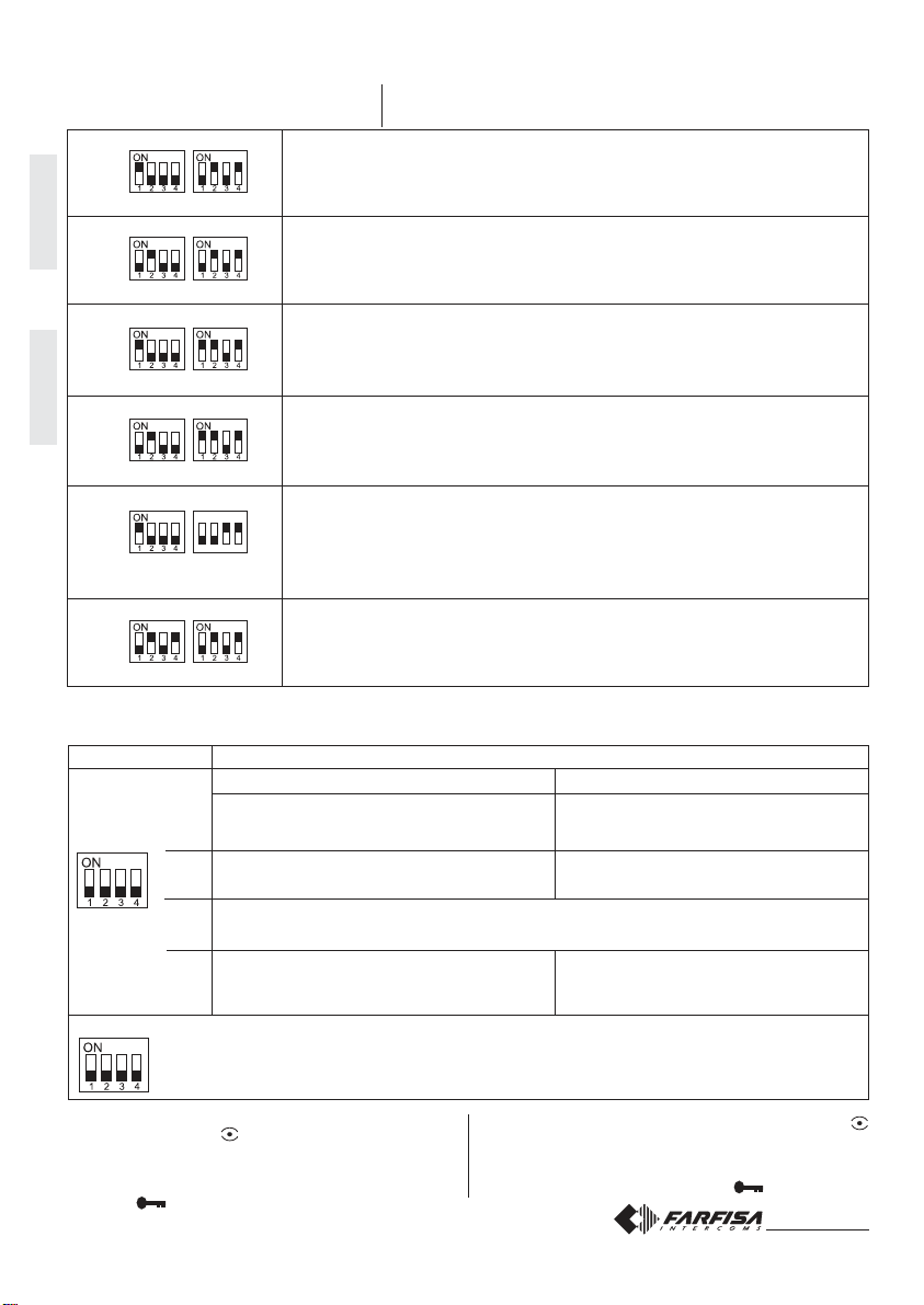
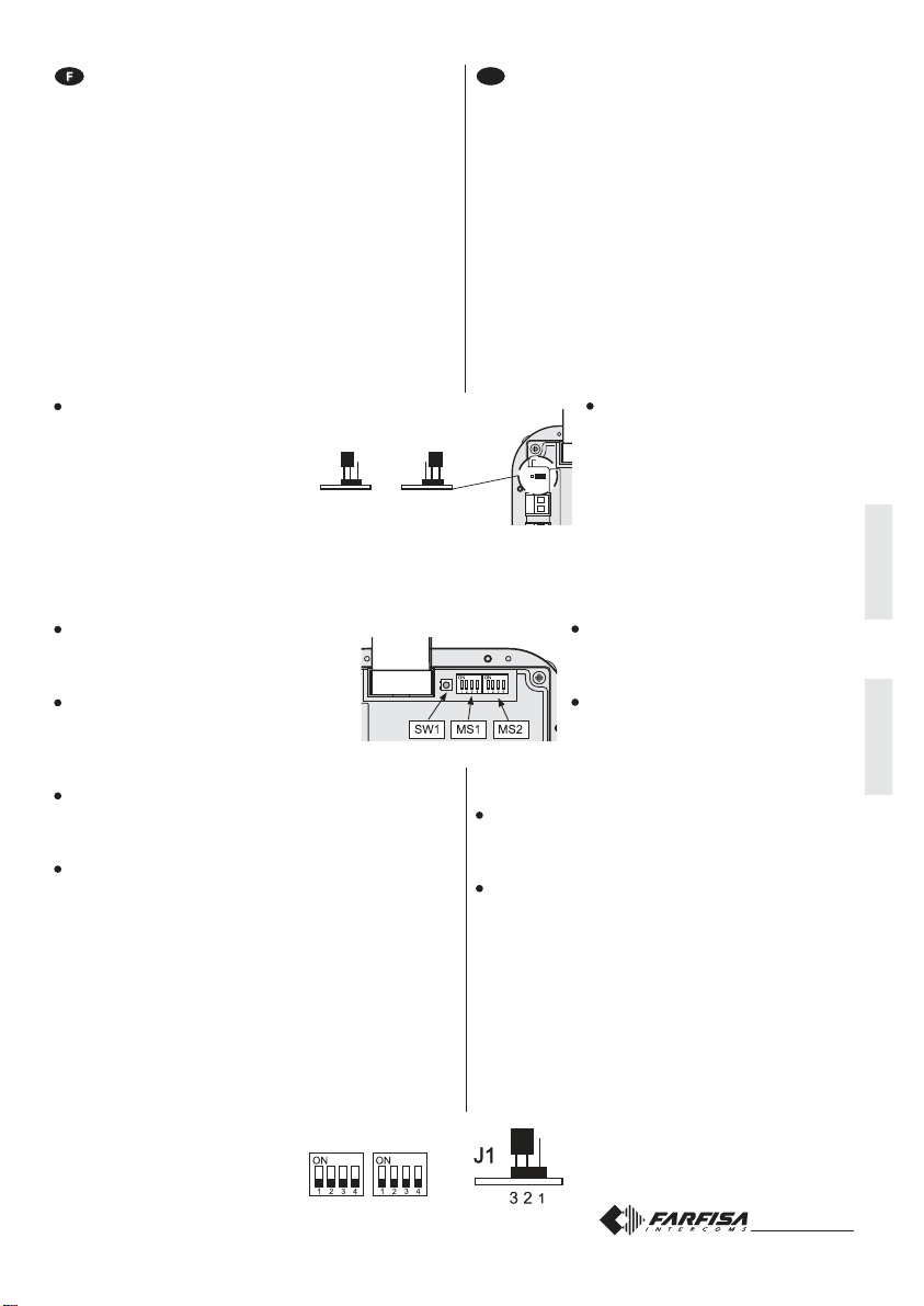
PROGRAMMAZIONI
Per effettuare le programmazioni occorre eseguire le se-
guentifasi:
1) entrare in modalità programmazione
2) inserire il codice della programmazione che s'inten-
de effettuare
3) inserirel'indirizzorichiestooilcodicedellafunzione
desiderata
4) uscire dalla programmazione
Note
- In qualunque momento è possibile uscire dalla fase di
programmazioneseguendoleindicazionidelparagrafo4.
- Pereseguirealtreprogrammazionièsufficienteripeterepiù
volte le fasi 2 e 3.
1) ENTRATAINMODALITÀPROGRAMMAZIONE
Spostare il ponticello J1,posto sul
retrodellapulsantiera,dallaposizione
2-3alla1-2;siudràiltonodiprogram-
mazione.
Posizioni ponticello J1
1-2 =modalitàprogrammazione
2-3=modalitàfunzionamento
2) INSERIMENTOCODICIDISELEZIONEDELLAPRO-
GRAMMAZIONE
SuimicrointerruttoriMS1eMS2,impo-
stare il codice della programmazione
che s'intende eseguire come riportato
nella tabella 1 (codici 1A,2A,1B,2B,
1C e AA).
Premere il tasto di conferma SW.
3) PROGRAMMAZIONEINDIRIZZOOCODICEFUNZIO-
NE
SuimicrointerruttoriMS1eMS2,impostarel'indirizzodesi-
deratousando la corrispondenza riportatanella tabella 3.
Per le programmazioni di sistema (codice 2B) vedere la
tabella2.
Premere il tasto di conferma SW.
- Ripeterepiùvoltelefasi2e3finoallacompletaprogramma-
zionedelcodificatore.
- Ad ogni pressione del tasto SW un tono di conferma o di
errore indicherà l'immissione di un codice corretto o sba-
gliato;nelsecondocasosarà necessario reinserireilcodi-
ceesatto.
4) USCITADALLAMODALITÀPROGRAMMAZIONE
Per uscire dalla programmazione è necessario posizionare
tutti i microinterruttori di MS1 e MS2 su OFF e riportare il
ponticelloJ1 dalla posizione 1-2 alla 2-3.
PROGRAMMING
Toprogramthedeviceitisnecessarytoperformthefollowing
phases:
1) enterprogrammingmode
2) insertcodeofdesiredprogramming
3) insertrequiredaddressorfunctionalcode
4) exitprogrammingmode
Notes
-In any situation it would be possible to exit the program-
ming phase following the instructions reported on para-
graph 4.
-To proceed with other programming repeat the phases 2
and 3.
1) ENTERPROGRAMMINGMODE
Move the jumper J1 from 2-3 to 1-2
position; a programming tone will con-
firm the correct operation.
Position of jumper J1
1-2 = programming mode
2-3 = operating mode
2) INSERTCODEOFDESIRED PROGRAMMING
On the micro-switches MS1 and MS2 set
the code corresponding to the program-
ming operation you wish to enter as re-
portedontable1(codes1A,2A,1B,2B,1C
and AA).
Press the programming button SW.
3) INSERTREQUIREDADDRESS OR FUNCTIONAL
CODE
On the microswitches MS1 and MS2 set the address you
wish to enter in accordance with the cross-references
reported on table 3.
For system programming see table 2 (code 2B).
Press the programming button SW.
-Repeat phases 2 and 3 until you have completely pro-
grammed the Digital Encoder.
-AnytimeyoupresstheSWbuttonanacknowledgeorerror
tonewillwarningyouwhethertheenteredcodeiscorrector
not; in case of incorrect code you must enter again the
correctone.
4) EXITPROGRAMMINGMODE
Toexittheprogrammingphaseit isnecessarytosetOFFall
themicroswitchesMS1andMS2andmovebackthejumper
J1 from 1-2 to 2-3 position.
MS1 MS2
LP
LP
J1 J1
1-2 2-3
J1
112233
Mi 2318/1 14
ON
délai d’activation de la gâche; 6 secondes
tiempo de accionamiento de la cerradura; 6 segundos
appel depuis un interne activé à cette fonction
llamada desde la extensión no habilitada
NON UTILISÉ: laisser en position OFF
NO UTILIZADO: dejar en posición OFF
générateurdetonalitéssurlepostederue;NONactivé*
generadordetonosenlaplacade calle;NOhabilitado*
OFF
délai d’activation de la gâche; 3 secondes
tiempode accionamientocerradura;3 segundos
appel depuis un interne NON activé *
llamada desde la extensión NO habilitada *
générateurdetonalitéssurlepostederue;activé
generadordetonosenlaplacadecalle;habilitado
1
2
3
4
MS1 MS2
1A
2A
1B
2B
1C
AA
Tableau 1 - tabla 1
Codes de sélection de la programmation
Códigosdeseleccióndelaprogramación
Adresseaffectée au premier bouton-poussoir d’appel.Codesde 1 à 200(voirtableau
3).
Dirección asociada al primer pulsador de llamada. Códigos de 1 a 200 (ver tabla 3).
Adresseaffectéeaudernierbouton-poussoird’appel.Codesde1à200(voirtableau3).
Dirección asociada al último pulsador de llamada. Códigos de 1 a 200 (ver tabla 3).
Adresse du poste de rue. Codes de 231 à 250 (voir tableau 3).
Dirección de la placa de calle. Códigos de 231 a 250 (ver tabla 3).
Programmationsdesystème(voirtableau2).
Programaciones del sistema (ver tabla 2).
Présence du standard deconciergerie. Saisir l’adresse 201 sileplaquederue envoie
desappelsà1ouplusieursstandardsprincipauxoul’adresse210s’ilenvoiedesappels
à1ouplusieursstandardssecondaires(voirtableau3).
Presencia de centralita de conserjería. Introducir la dirección 201 si la placa de calle
envía llamadas a 1 o más centralitas principales o bien la dirección 210 si la placa de
calle envía llamadas a 1 o más centralitas secundarias (ver tabla 3).
Rétablirlaprogrammation d’usine. Code 85(voirtableau 3).
Restauración de la programación por defecto. Código 85 (ver tabla 3).
MS1 MS2
1A
2A
MS1 MS2
MS1 MS2
1B
2B
MS1
ON
1234
MS2
1C
Tableau 2 - tabla 2
Codesdesprogrammationsdesystème (code2B) -Códigosprogramacionesdesistema(código2B)
Positiondesmicro-interrupteursdeMS1-MS2 Posiciónmicro-interruptoresdeMS1-MS2
Micro-interrupteurs
Micro-interruptores
MS1
MS2 Pendant ces programmations tous les micro-interrupteurs de MS2 doivent rester en position OFF
Duranteestasprogramacionestodoslosmicro-interruptoresdeMS2tienenquequedarenposición
OFF
Adresse ou fonction à programmer
Direcciónofunción aprogramar
MS1 MS2
AA
* Enactivantcettefonction,onpeut,depuischaqueinterne,en
appuyantsurlebouton-poussoir ,engageruneconversa-
tion avec le poste de rue (si plusieurs postes de rue en
parallèle sont installés, la conversation s’engage avec le
dernierposte de rue duquelun appel a étéeffectué)et, en
appuyantsurlebouton-poussoir ,activerlagâche.
* Una vez habilitada esta función, es posible, presionando
latecla encualquieraparatointerno,entrarenconver-
sación con una placa de calle (en caso de varias placas
de calle en paralelo se entrará en comunicación con la
última placa de calle que ha realizado la llamada), y,
siemprepresionando la tecla , accionar la cerradura.
ITALIANOENGLISHFRANÇAISESPAÑOLPORTUGUÊSDEUTSCH
ITALIANOENGLISHFRANÇAISESPAÑOLPORTUGUÊSDEUTSCH
Mi 2318/1 12
ON
tempodiazionamentodellaserratura;6secondi
door lock activation time; 6 seconds
chiamatadainternoabilitata
activation upon call from internal station
NONUSATO:lasciareinposizioneOFF
NOT USED: to leave in position OFF
generatoreditonisulpostoesterno;NONabilitato*
DEACTIVATIONof tone generatoronthe external
door station *
OFF
tempodiazionamentodellaserratura;3sec.
door lock activation time; 3 seconds
chiamatadainternoNONabilitata*
deactivation upon call from internal station *
generatoreditoni sul posto esterno; abilitato
ACTIVATIONoftonegenerator ontheexter-
nal door station
1
2
3
4
MS1 MS2
1A
2A
1B
2B
1C
AA
Tabella 1 - table 1
Codici di selezione della programmazione
Selectioncodeoftheprogramming
Indirizzoassociatoal primopulsantedichiamata.Codicida1a200(vederetabella3).
User address associated to the first button. Codes from 1 to 200 (see table 3).
Indirizzoassociatoall'ultimopulsantedichiamata.Codicida1a200(vederetabella3).
User address associated to the last button. Codes from 1 to 200 (see table 3).
Indirizzo del posto esterno. Codici da 231 a 250 (vedere tabella 3).
Address of the external door station. Codes from 231 to 250 (see table 3).
Programmazionidi sistema (vedere tabella 2).
System programming (see table 2).
Presenzacentralinodiportineria.Inserireindirizzo201selapulsantierainviachiamate
ad1opiùcentraliniprincipalioppurel’indirizzo210 selapulsantierainviachiamatead
1o più centralini secondari(vederetabella3).
Settings for operations with a door keeper echanger. Enter address 201 if the door
stationoperateswith1ormoremain doorkeeperexchangersor theaddress210 ifthe
doorstationoperates with1ormoresecondary doorkeeperexchangers(see table3).
Ritorno alla programmazione di fabbrica. Codice 85 (vedere tabella 3).
Set the device back to factory settings. Code 85 (see table 3).
MS1 MS2
1A
2A
MS1 MS2
MS1 MS2
1B
2B
MS1
ON
1234
MS2
1C
Tabella 2 - table 2
Programmazioni di sistema (modo 2B) - Operating mode of the system (code 2B)
Posizionemicrointerruttoridi MS1 -MS2 Microswitchespositionof MS1andMS2
Microinterruttori
Micro-switches
MS1
MS2 Durante queste programmazioni tutti i microinterruttori di MS2 devono rimanere in posizione OFF
During these programmings all the micro-switches of MS2 have to remain in position OFF
Indirizzo o funzione da programmare
Addressorfunctiontobeprogrammed
MS1 MS2
AA
* Abilitando questa funzione da ogni interno è possibile,
premendo il pulsante , entrare in conversazione con un
posto esterno (nel caso di più posti esterni in parallelo si
entra in comunicazione con l'ultimo posto esterno che ha
effettuatolachiamata)edazionarelaserraturapremendoil
pulsante .
* This function allows the internal stations to press the
button, start a conversation with the external station (in
caseofmoreexternalstationsinparalleltheconnectionis
established with the last calling door station) and activate
the door lock by pressing the button .
Mi 2318/1 13
PROGRAMMATIONS
Poureffectuerlesprogrammations,ilfautprocédercommesuit:
1) entrer en mode de programmation
2) saisirlecodedelaprogrammationquel’onveuteffectuer
3) saisir l’adresse demandée ou le code de la fonction
désirée
4) quitter la programmation
Note
- Onpeutquitteràtousmomentslaprogrammationenprocédant
telqu’expliquédansleparagraphe4.
- Pourprocéderàd’autresprogrammations,ilsuffitderépéter
autant de fois que nécessaire les phases 2 et 3.
1) ENTRERENMODEDEPROGRAMMATION
Déplacer le pontet J1,positionné en
facearrièrede laplaquederue, dela
position 2-3 à la 1-2; ont entend la
tonalitédeprogrammation.
Positions du pontet J1
1-2 = mode de programmation
2-3=modedefonctionnement
2) SAISIR LES CODES DE SÉLECTION DE LA PRO-
GRAMMATION
Sur les micro-interrupteurs MS1 et MS2,
prédisposerlecodedeprogrammationque
l’onveutprogrammer,telqu’indiquédansle
tableau1(codes1A,2A,1B,2B,1CetAA).
Appuyer sur la touche de programmation
SW.
3) PROGRAMMERL’ADRESSEOULECODEFONCTION
Surlesmicro-interrupteursMS1etMS2,prédisposerl’adresse
désirée en utilisant la correspondance indiquée dans le
tableau 3.Pour lesprogrammations de système (code 2B),
voirletableau2.
AppuyersurlatouchedeprogrammationSW.
- Répéter autant de fois que nécessaire les phases 2 et 3,
jusqu’àcompléterlaprogrammationducodeur.
- A chaque pression du bouton-poussoir SW, une tonalité de
confirmationoud’erreurindiqueralasaisied’uncodecorrect
ouerroné;danscecas,ilfautprocéderàunenouvellesaisie
ducodecorrect.
4) QUITTERLEMODEDEPROGRAMMATION
Pourquitterlaprogrammation,ilfautpositionnertouslesmicro-
interrupteursdeMS1etMS2surOFFetrétablirlepontetJ1de
la position 1-2 à la 2-3.
E
PROGRAMACIONES
Para efectuar las programaciones se necesitan realizar
las fases siguientes:
1) entrarenmododeprogramación
2) insertarel códigodelaprogramaciónarealizar
3) insertar la dirección solicitada o el código de la
funcióndeseada
4) salirdelaprogramación
Notas
- Se puede salir de la fase de programación en cualquier
momento siguiendo las instrucciones del apartado 4.
- Para realizar otras programaciones es suficiente repetir
más veces las fases 2 y 3.
1) ENTRARENMODODEPROGRAMACIÓN
Cambiar el puente J1, que se en-
cuentra en la parte posterior de la
placa de pulsadores, de la posición
2-3ala1-2;seoyeeltonodeprogra-
mación.
Posiciones puente J1
1-2 = modo de programación
2-3 = modo de funcionamiento
2) INSERCIÓN CÓDIGOS DE SELECCIÓN DE LA
PROGRAMACIÓN
En los microinterruptores MS1 y MS2
ajustar el código de la programación a
realizar según ilustrado en la tabla 1 (có-
digos 1A,2A,1B,2B,1C y AA).
Presionar la tecla de programación SW.
3) PROGRAMACIÓNDIRECCIÓNOCÓDIGOFUN-
CIÓN
En los microinterruptores MS1 y MS2 ajustar la direc-
ción deseada utilizando la correspondencia ilustrada
en la tabla 3. Para las programaciones de sistema
(código 2B) véase la tabla 2.
Presionar la tecla de programación SW.
- Repetir más veces las fases 2 y 3 hasta programar
completamente el codificador.
- A cada presión de la tecla SW un tono de confirmación
o error indicará la inserción de un código correcto o
equivocado; en el segundo caso se necesita volver a
insertar el código exacto.
4) SALIRDELMODODEPROGRAMACIÓN
Para salir de la programación es necesario colocar todos
los micro-interruptores de MS1 y MS2 en OFF y pasar el
puente J1 de la posición 1-2 a la 2-3.
LP
LP
J1 J1
1-2 2-3
J1
112233
MS1 MS2
ITALIANOENGLISHFRANÇAISESPAÑOLPORTUGUÊSDEUTSCH
ITALIANOENGLISHFRANÇAISESPAÑOLPORTUGUÊSDEUTSCH
Mi 2318/1 12
ON
tempodiazionamentodellaserratura;6secondi
door lock activation time; 6 seconds
chiamatadainternoabilitata
activation upon call from internal station
NONUSATO:lasciareinposizioneOFF
NOT USED: to leave in position OFF
generatoreditonisulpostoesterno;NONabilitato*
DEACTIVATIONof tone generatoronthe external
door station *
OFF
tempodiazionamentodellaserratura;3sec.
door lock activation time; 3 seconds
chiamatadainternoNONabilitata*
deactivation upon call from internal station *
generatoreditoni sul posto esterno; abilitato
ACTIVATIONoftonegenerator ontheexter-
nal door station
1
2
3
4
MS1 MS2
1A
2A
1B
2B
1C
AA
Tabella 1 - table 1
Codici di selezione della programmazione
Selectioncodeoftheprogramming
Indirizzoassociatoal primopulsantedichiamata.Codicida1a200(vederetabella3).
User address associated to the first button. Codes from 1 to 200 (see table 3).
Indirizzoassociatoall'ultimopulsantedichiamata.Codicida1a200(vederetabella3).
User address associated to the last button. Codes from 1 to 200 (see table 3).
Indirizzo del posto esterno. Codici da 231 a 250 (vedere tabella 3).
Address of the external door station. Codes from 231 to 250 (see table 3).
Programmazionidi sistema (vedere tabella 2).
System programming (see table 2).
Presenzacentralinodiportineria.Inserireindirizzo201selapulsantierainviachiamate
ad1opiùcentraliniprincipalioppurel’indirizzo210 selapulsantierainviachiamatead
1o più centralini secondari(vederetabella3).
Settings for operations with a door keeper echanger. Enter address 201 if the door
stationoperateswith1ormoremain doorkeeperexchangersor theaddress210 ifthe
doorstationoperates with1ormoresecondary doorkeeperexchangers(see table3).
Ritorno alla programmazione di fabbrica. Codice 85 (vedere tabella 3).
Set the device back to factory settings. Code 85 (see table 3).
MS1 MS2
1A
2A
MS1 MS2
MS1 MS2
1B
2B
MS1
ON
1234
MS2
1C
Tabella 2 - table 2
Programmazioni di sistema (modo 2B) - Operating mode of the system (code 2B)
Posizionemicrointerruttoridi MS1 -MS2 Microswitchespositionof MS1andMS2
Microinterruttori
Micro-switches
MS1
MS2 Durante queste programmazioni tutti i microinterruttori di MS2 devono rimanere in posizione OFF
During these programmings all the micro-switches of MS2 have to remain in position OFF
Indirizzo o funzione da programmare
Addressorfunctiontobeprogrammed
MS1 MS2
AA
* Abilitando questa funzione da ogni interno è possibile,
premendo il pulsante , entrare in conversazione con un
posto esterno (nel caso di più posti esterni in parallelo si
entra in comunicazione con l'ultimo posto esterno che ha
effettuatolachiamata)edazionarelaserraturapremendoil
pulsante .
* This function allows the internal stations to press the
button, start a conversation with the external station (in
caseofmoreexternalstationsinparalleltheconnectionis
established with the last calling door station) and activate
the door lock by pressing the button .
Mi 2318/1 13
PROGRAMMATIONS
Poureffectuerlesprogrammations,ilfautprocédercommesuit:
1) entrer en mode de programmation
2) saisirlecodedelaprogrammationquel’onveuteffectuer
3) saisir l’adresse demandée ou le code de la fonction
désirée
4) quitter la programmation
Note
- Onpeutquitteràtousmomentslaprogrammationenprocédant
telqu’expliquédansleparagraphe4.
- Pourprocéderàd’autresprogrammations,ilsuffitderépéter
autant de fois que nécessaire les phases 2 et 3.
1) ENTRERENMODEDEPROGRAMMATION
Déplacer le pontet J1,positionné en
facearrièrede laplaquederue, dela
position 2-3 à la 1-2; ont entend la
tonalitédeprogrammation.
Positions du pontet J1
1-2 = mode de programmation
2-3=modedefonctionnement
2) SAISIR LES CODES DE SÉLECTION DE LA PRO-
GRAMMATION
Sur les micro-interrupteurs MS1 et MS2,
prédisposerlecodedeprogrammationque
l’onveutprogrammer,telqu’indiquédansle
tableau1(codes1A,2A,1B,2B,1CetAA).
Appuyer sur la touche de programmation
SW.
3) PROGRAMMERL’ADRESSEOULECODEFONCTION
Surlesmicro-interrupteursMS1etMS2,prédisposerl’adresse
désirée en utilisant la correspondance indiquée dans le
tableau 3.Pour lesprogrammations de système (code 2B),
voirletableau2.
AppuyersurlatouchedeprogrammationSW.
- Répéter autant de fois que nécessaire les phases 2 et 3,
jusqu’àcompléterlaprogrammationducodeur.
- A chaque pression du bouton-poussoir SW, une tonalité de
confirmationoud’erreurindiqueralasaisied’uncodecorrect
ouerroné;danscecas,ilfautprocéderàunenouvellesaisie
ducodecorrect.
4) QUITTERLEMODEDEPROGRAMMATION
Pourquitterlaprogrammation,ilfautpositionnertouslesmicro-
interrupteursdeMS1etMS2surOFFetrétablirlepontetJ1de
la position 1-2 à la 2-3.
E
PROGRAMACIONES
Para efectuar las programaciones se necesitan realizar
las fases siguientes:
1) entrarenmododeprogramación
2) insertarel códigodelaprogramaciónarealizar
3) insertar la dirección solicitada o el código de la
funcióndeseada
4) salirdelaprogramación
Notas
- Se puede salir de la fase de programación en cualquier
momento siguiendo las instrucciones del apartado 4.
- Para realizar otras programaciones es suficiente repetir
más veces las fases 2 y 3.
1) ENTRARENMODODEPROGRAMACIÓN
Cambiar el puente J1, que se en-
cuentra en la parte posterior de la
placa de pulsadores, de la posición
2-3ala1-2;seoyeeltonodeprogra-
mación.
Posiciones puente J1
1-2 = modo de programación
2-3 = modo de funcionamiento
2) INSERCIÓN CÓDIGOS DE SELECCIÓN DE LA
PROGRAMACIÓN
En los microinterruptores MS1 y MS2
ajustar el código de la programación a
realizar según ilustrado en la tabla 1 (có-
digos 1A,2A,1B,2B,1C y AA).
Presionar la tecla de programación SW.
3) PROGRAMACIÓNDIRECCIÓNOCÓDIGOFUN-
CIÓN
En los microinterruptores MS1 y MS2 ajustar la direc-
ción deseada utilizando la correspondencia ilustrada
en la tabla 3. Para las programaciones de sistema
(código 2B) véase la tabla 2.
Presionar la tecla de programación SW.
- Repetir más veces las fases 2 y 3 hasta programar
completamente el codificador.
- A cada presión de la tecla SW un tono de confirmación
o error indicará la inserción de un código correcto o
equivocado; en el segundo caso se necesita volver a
insertar el código exacto.
4) SALIRDELMODODEPROGRAMACIÓN
Para salir de la programación es necesario colocar todos
los micro-interruptores de MS1 y MS2 en OFF y pasar el
puente J1 de la posición 1-2 a la 2-3.
LP
LP
J1 J1
1-2 2-3
J1
112233
MS1 MS2

ITALIANOENGLISHFRANÇAISESPAÑOLPORTUGUÊSDEUTSCH
ITALIANOENGLISHFRANÇAISESPAÑOLPORTUGUÊSDEUTSCH
Mi 2318/1 11
PROGRAMMAZIONI
Per effettuare le programmazioni occorre eseguire le se-
guentifasi:
1) entrare in modalità programmazione
2) inserire il codice della programmazione che s'inten-
de effettuare
3) inserirel'indirizzorichiestooilcodicedellafunzione
desiderata
4) uscire dalla programmazione
Note
- In qualunque momento è possibile uscire dalla fase di
programmazioneseguendoleindicazionidelparagrafo4.
- Pereseguirealtreprogrammazionièsufficienteripeterepiù
volte le fasi 2 e 3.
1) ENTRATAINMODALITÀPROGRAMMAZIONE
Spostare il ponticello J1,posto sul
retrodellapulsantiera,dallaposizione
2-3alla1-2;siudràiltonodiprogram-
mazione.
Posizioni ponticello J1
1-2 =modalitàprogrammazione
2-3=modalitàfunzionamento
2) INSERIMENTOCODICIDISELEZIONEDELLAPRO-
GRAMMAZIONE
SuimicrointerruttoriMS1eMS2,impo-
stare il codice della programmazione
che s'intende eseguire come riportato
nella tabella 1 (codici 1A,2A,1B,2B,
1C e AA).
Premere il tasto di conferma SW.
3) PROGRAMMAZIONEINDIRIZZOOCODICEFUNZIO-
NE
SuimicrointerruttoriMS1eMS2,impostarel'indirizzodesi-
deratousando la corrispondenza riportatanella tabella 3.
Per le programmazioni di sistema (codice 2B) vedere la
tabella2.
Premere il tasto di conferma SW.
- Ripeterepiùvoltelefasi2e3finoallacompletaprogramma-
zionedelcodificatore.
- Ad ogni pressione del tasto SW un tono di conferma o di
errore indicherà l'immissione di un codice corretto o sba-
gliato;nelsecondocasosarà necessario reinserireilcodi-
ceesatto.
4) USCITADALLAMODALITÀPROGRAMMAZIONE
Per uscire dalla programmazione è necessario posizionare
tutti i microinterruttori di MS1 e MS2 su OFF e riportare il
ponticelloJ1 dalla posizione 1-2 alla 2-3.
PROGRAMMING
Toprogramthedeviceitisnecessarytoperformthefollowing
phases:
1) enterprogrammingmode
2) insertcodeofdesiredprogramming
3) insertrequiredaddressorfunctionalcode
4) exitprogrammingmode
Notes
-In any situation it would be possible to exit the program-
ming phase following the instructions reported on para-
graph 4.
-To proceed with other programming repeat the phases 2
and 3.
1) ENTERPROGRAMMINGMODE
Move the jumper J1 from 2-3 to 1-2
position; a programming tone will con-
firm the correct operation.
Position of jumper J1
1-2 = programming mode
2-3 = operating mode
2) INSERTCODEOFDESIRED PROGRAMMING
On the micro-switches MS1 and MS2 set
the code corresponding to the program-
ming operation you wish to enter as re-
portedontable1(codes1A,2A,1B,2B,1C
and AA).
Press the programming button SW.
3) INSERTREQUIREDADDRESS OR FUNCTIONAL
CODE
On the microswitches MS1 and MS2 set the address you
wish to enter in accordance with the cross-references
reported on table 3.
For system programming see table 2 (code 2B).
Press the programming button SW.
-Repeat phases 2 and 3 until you have completely pro-
grammed the Digital Encoder.
-AnytimeyoupresstheSWbuttonanacknowledgeorerror
tonewillwarningyouwhethertheenteredcodeiscorrector
not; in case of incorrect code you must enter again the
correctone.
4) EXITPROGRAMMINGMODE
Toexittheprogrammingphaseit isnecessarytosetOFFall
themicroswitchesMS1andMS2andmovebackthejumper
J1 from 1-2 to 2-3 position.
MS1 MS2
LP
LP
J1 J1
1-2 2-3
J1
112233
Mi 2318/1 14
ON
délai d’activation de la gâche; 6 secondes
tiempo de accionamiento de la cerradura; 6 segundos
appel depuis un interne activé à cette fonction
llamada desde la extensión no habilitada
NON UTILISÉ: laisser en position OFF
NO UTILIZADO: dejar en posición OFF
générateurdetonalitéssurlepostederue;NONactivé*
generadordetonosenlaplacade calle;NOhabilitado*
OFF
délai d’activation de la gâche; 3 secondes
tiempode accionamientocerradura;3 segundos
appel depuis un interne NON activé *
llamada desde la extensión NO habilitada *
générateurdetonalitéssurlepostederue;activé
generadordetonosenlaplacadecalle;habilitado
1
2
3
4
MS1 MS2
1A
2A
1B
2B
1C
AA
Tableau 1 - tabla 1
Codes de sélection de la programmation
Códigosdeseleccióndelaprogramación
Adresseaffectée au premier bouton-poussoir d’appel.Codesde 1 à 200(voirtableau
3).
Dirección asociada al primer pulsador de llamada. Códigos de 1 a 200 (ver tabla 3).
Adresseaffectéeaudernierbouton-poussoird’appel.Codesde1à200(voirtableau3).
Dirección asociada al último pulsador de llamada. Códigos de 1 a 200 (ver tabla 3).
Adresse du poste de rue. Codes de 231 à 250 (voir tableau 3).
Dirección de la placa de calle. Códigos de 231 a 250 (ver tabla 3).
Programmationsdesystème(voirtableau2).
Programaciones del sistema (ver tabla 2).
Présence du standard deconciergerie. Saisir l’adresse 201 sileplaquederue envoie
desappelsà1ouplusieursstandardsprincipauxoul’adresse210s’ilenvoiedesappels
à1ouplusieursstandardssecondaires(voirtableau3).
Presencia de centralita de conserjería. Introducir la dirección 201 si la placa de calle
envía llamadas a 1 o más centralitas principales o bien la dirección 210 si la placa de
calle envía llamadas a 1 o más centralitas secundarias (ver tabla 3).
Rétablirlaprogrammation d’usine. Code 85(voirtableau 3).
Restauración de la programación por defecto. Código 85 (ver tabla 3).
MS1 MS2
1A
2A
MS1 MS2
MS1 MS2
1B
2B
MS1
ON
1234
MS2
1C
Tableau 2 - tabla 2
Codesdesprogrammationsdesystème (code2B) -Códigosprogramacionesdesistema(código2B)
Positiondesmicro-interrupteursdeMS1-MS2 Posiciónmicro-interruptoresdeMS1-MS2
Micro-interrupteurs
Micro-interruptores
MS1
MS2 Pendant ces programmations tous les micro-interrupteurs de MS2 doivent rester en position OFF
Duranteestasprogramacionestodoslosmicro-interruptoresdeMS2tienenquequedarenposición
OFF
Adresse ou fonction à programmer
Direcciónofunción aprogramar
MS1 MS2
AA
* Enactivantcettefonction,onpeut,depuischaqueinterne,en
appuyantsurlebouton-poussoir ,engageruneconversa-
tion avec le poste de rue (si plusieurs postes de rue en
parallèle sont installés, la conversation s’engage avec le
dernierposte de rue duquelun appel a étéeffectué)et, en
appuyantsurlebouton-poussoir ,activerlagâche.
* Una vez habilitada esta función, es posible, presionando
latecla encualquieraparatointerno,entrarenconver-
sación con una placa de calle (en caso de varias placas
de calle en paralelo se entrará en comunicación con la
última placa de calle que ha realizado la llamada), y,
siemprepresionando la tecla , accionar la cerradura.

ITALIANOENGLISHFRANÇAISESPAÑOLPORTUGUÊSDEUTSCH
ITALIANOENGLISHFRANÇAISESPAÑOLPORTUGUÊSDEUTSCH
Mi 2318/1 8
J1 = 1-2 chiusura/termination/fermeture47Ω
cierre / fechadura / Schließung
3-4 chiusura/termination/fermeture70Ω
cierre / fechadura / Schließung
4-5 chiusura/termination/fermeture100Ω
cierre / fechadura / Schließung
Si51VM/2
IMPIANTO MISTO CITOFONICO-VIDEOCITOFONICO COLLEGATO AD UN POSTO ESTERNO
MIXED INTERCOM-VIDEOINTERCOM SYSTEM CONNECTED TO ONE EXTERNAL DOOR STATION
INSTALLATION MIXTE INTERPHONIQUE-VIDÉOPHONIQUE BRANCHÉE À UN POSTE DE RUE
SISTEMA MIXTO DE PORTERO-VIDEOPORTERO CONECTADO A UNA PLACA DE CALLE
INSTALAÇÃO MISTA DE TELEFONES PORTEIRO-VÍDEO-PORTEIRO LIGADO A UM POSTO EXTERNO
VIDEOSPRECHANLAGE MIT GEMISCHTEN VIDEOHAUSTELEFONE / HAUSTELEFONE
PA = Pulsanteapriporta(opzionale)
Doorreleasepush-button(optional)
Bouton-poussoirouvreporte(optionnel)
Pulsadorabrepuerta(opcional)
Botãoparaabriraporta(opcional)
ZusätzlicheTüröffnertaste(Ergänzung)
SE = Serraturaelettrica(12Vca-1Amax.)
Electric door lock (12VAC-1A max)
Gâcheélectrique(12Vca-1Amax)
Cerraduraeléctrica(12Vca-1Amáx.)
Fechaduraeléctrica(12Vca-1Amax)
Türöffner(12Vac-1Amax)
FP= Pulsante chiamata dipiano (opzionale)
Floorcall push-button (optional)
Bouton-poussoirdepalier(optionnel)
Pulsadordepiso(opcional)
Botãodepatamar(opcional)
Etagenruftaste(Ergänzung)
DV2420
D
J1
12345
J1
12345
LM
LM
PA
SE
2220S
2220
230V
230V
127V
127V
0
0
DV2421P
DV2421P
LM
LM
LM
LM
LI LI
LO
LO
LO
LO
LI LI
LM
LM
A1
GN
LM
LM
A1
GN
FP
FP
A
B
E
E
C
ML2002+ML2083
EH9262+9083
EX3262+WB3262
KM8262+WB8262
EX362
KM862
ML2002+ML2083
EH9262+9083
EX3262+WB3262
KM8262+WB8262
EX362
KM862
LO LO
LI LI
J1
12345
J1
12345
J1
12345
2221S2221ML
LP
LP
LP
LP
PRI
110V÷240VAC
VD2120CMAS
LP
LP
P1
P1
EC
EM
S1
S2
F
CD2131MAS
CD2132MAS
CD2134MAS
J1 = 2-3 linea aperta / open line / ligne ouverte
líneaabierta /linhaaberta/offeneLinie
J1 = 2-3 linea aperta / open line / ligne ouverte
líneaabierta /linhaaberta/offeneLinie
Mi 2318/1 17
Tabella 3
Corrispondenza tra i codici e la posi-
zione dei microinterruttori di MS1 e
MS2.
Table 3
Cross-reference between codes and
microswitches position of MS1 and
MS2.
Tableau2
Tableau de correspondance entre les
codes et la position des micro-
interrupteurs de MS1 et MS2.
Tabla de correspondencia entre los
códigos y la posición de los micro-
interruptores de MS1 y MS2.
Tabela de correspondência entre
os códigos e a posição dos
microinterruptores de MS1 e MS2.
Tabelle der Übereinstimmung zwischen
Codes und Mikroschalterposition bei
MS1 und MS2
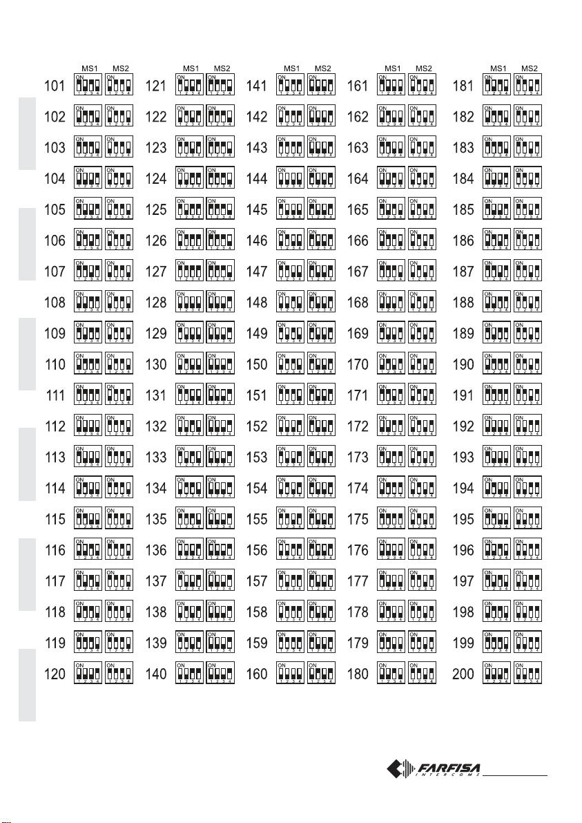
ITALIANOENGLISHFRANÇAISESPAÑOLPORTUGUÊSDEUTSCH
ITALIANOENGLISHFRANÇAISESPAÑOLPORTUGUÊSDEUTSCH
Mi 2318/1 7
chiusura / termination / fermeture
cierre / fechadura / Schließung
J1 = 1-2 = 47Ω
3-4 = 70Ω
4-5 = 100Ω
2 POSTI INTERNI IN PARALLELO
2 APARATOS INTERNOS EN
PARALELO
Nei riquadri vi sono gli articoli aggiuntivi
agli schemi base delle pagine 8 e 9.
En los cuadros se indican los artículos
adicionales a los diagramas básicos de
las páginas 8 y 9.
3 POSTI INTERNI IN PARALLELO
3 APARATOS INTERNOS EN
PARALELO
Inthe dashedboxes areshown theitems
to add the basic diagrams reported at
pages 8 and 9.
Osquadrosilustramosartigosadicionais
aos esquemas-base das páginas 8 e 9.
2 POSTES INTERNES EN PARALLELE
2 INTERNE GERÄTE PARALLEL
Voir dans les cases les articles supplémen-
tairesauxschémasdebasedespages8et9.
In den Kästen sind die gegenüber den
BasisschaltplänenaufSeite8und9zusätzlich
zu verwendenden Artikel aufgeführt.
3 POSTES INTERNES EN PARALLELE
3 INTERNE GERÄTE PARALLEL
2 PARALLEL INTERNAL STATIONS
2 POSTOS INTERNOS EM
PARALELOS
3 PARALLEL INTERNAL STATIONS
3 POSTOS INTERNOS EM
PARALELOS
DV2421P
DV2421P
LM
LM
A1
GN
LM
LM
A1
GN
LM
LM
LI
LI
LO LO
J1
54321
LI LI
J1
J1
J1
5
5
5
4
4
4
3
3
3
2
2
2
1
1
1
ML2002+ML2083
EH9262+9083
EX3262+WB3262
KM8262+WB8262
EX362
KM862
E
ML2002+ML2083
EH9262+9083
EX3262+WB3262
KM8262+WB8262
EX362
KM862
DV2421P
DV2421P
LM
LM
A1
GN
LM
LM
A1
GN
LM
LM
A1
GN
LM
LM
LI
LI
LO LO
J1
54321
LI LI
J1
J1
J1
5
5
5
4
4
4
3
3
3
2
2
2
1
1
1
ML2002+ML2083
EH9262+9083
EX3262+WB3262
KM8262+WB8262
EX362
KM862
ML2002+ML2083
EH9262+9083
EX3262+WB3262
EX362
KM8262+WB8262
KM862
ML2002+ML2083
EH9262+9083
EX3262+WB3262
KM8262+WB8262
EX362
KM862
E
chiusura / termination
fermeture / cierre
fechadura / Schließung
J1 = 1-2 = 47Ω
3-4 = 70Ω
4-5 = 100Ω
Mi 2318/1 18
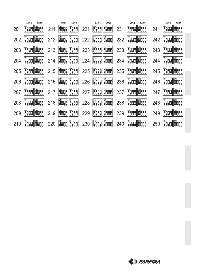
ITALIANOENGLISHFRANÇAISESPAÑOLPORTUGUÊSDEUTSCH
ITALIANOENGLISHFRANÇAISESPAÑOLPORTUGUÊSDEUTSCH
Mi 2318/1 6
Serratura elettrica
Comemostratoneisuccessivischemi
installativi,laserraturaelettricapuòes-
sereazionatadallostessoalimentato-
re che alimenta il posto esterno, ma
affinchèilsistemafunzionicorrettamen-
telaserraturaelettricadeveesseredel
tipo12Vca/1A max. Durantel'aziona-
mentodellaserraturailsegnalevideo
puòesseredisturbato.Perevitareque-
sto inconveniente o per azionare ser-
rature con caratteristiche differenti si
suggeriscediutilizzareunalimentato-
resupplementarecomeriportatonello
schemaseguente.
IMPORTANTE
Al fine di ottemperare alla Direttiva Euro-
pea sulla Compatibilità Elettromagnetica
eperaumentarel’affidabilitàdelprodotto,
ènecessarioconnettereun dispositivo di
soppressione dei disturbi quando si co-
manda un carico induttivo, per esempio
unaserraturaelettrica(SE).Isoppressori
inclusi(transil)devonoessereconnessiil
piùvicinopossibilealcarico(teoricamen-
te sui terminali dello stesso).
Electricdoorlock
As shown in the installation diagrams
the electric lock can be operated using
the same power supply which powers
thedoorstation,butforacorrectopera-
tion the electric lock must be a 12VAC/
1A max type. During the release of the
electric lock the video signal can be
disturbed. To avoid this inconvenient
or to operate a powerful electric lock it
wouldbeadvisabletouseanextrapower
supply as reported in the following dia-
gram.
VERY IMPORTANT
TocomplywiththeEuropeanStandardson
Electromagnetic Compatibility and to in-
crease the reliability of the product, it is
necessary to connect a suppression de-
vice when switching inductive loads i.e.
electric releases and electric locks (SE).
Theenclosedsuppressiondevices(transil)
mustbeconnectedasclose as possible to
the loads (ideally across the terminals.
See figure).
Gâche électrique
Tel qu’illustré dans les schémas
d’installationsuivants,lagâcheélectrique
peut être activée par la même
alimentationquialimentelepostederue
mais, pour que le système fonctionne
correctement, la gâche électrique doit
êtredutype12Vca/1Amax.ilsepeutque
le signal vidéo soit dérangé lors de
l’activation de la gâche. Pour éviter cet
inconvénientoupouractiverdesgâches
ayantdescaractéristiquesdifférents,on
suggère d’utiliser une alimentation
supplémentaire, tel qu’illustré dans le
schémasuivant.
IMPORTANT
Conformément à la Directive Européenne
sur la Compatibilité Electromagnétique et
pour augmenter la fiabilité du produit, il faut
connecter un dispositif de suppression des
dérangements quand on commande une
charge inductive, par exemple une serrure
électrique (SE). Les suppresseurs inclus
(transil) doivent être connectés le plus près
possible de la charge (théoriquement sur
les terminaux de la charge même).
Cerraduraeléctrica
Como se ve en los siguientes
diagramasdeinstalación,lacerradura
eléctrica se puede accionar por el
mismo alimentador que alimenta la
placa de calle, pero, para que el
sistema funcione correctamente, la
cerradura eléctrica debe ser del tipo
12Vca/1A max. Durante el funciona-
miento de la cerradura la señal de
vídeo puede ser perturbada. Para
evitarelinconvenienteoparaaccionar
cerraduras con diferentes caracte-
rísticas, se sugiere emplear un
alimentadoradicional,comoindicado
en el diagrama siguiente.
IMPORTANTE
Para el fin de obedecer a la Directiva
EuropeasobrelaCompatibilidadElectro-
magnética, y también para mejorar la
seguridad del producto es necesario co-
nectar un dispositivo de supresión de
estorbosalmandodeunacargainductiva,
porejemplounacerraduraeléctrica(SE).
Los supresores incluidos (transil) se de-
ben conectar lo más cerca posible al
mando (en teoría, directamente en los
terminales del mismo).
Fechadura elétrica
Como ilustrado nos esquemas de
instalação sucessivos, a fechadura
elétricapodeseracionadapelomesmo
alimentadorquealimentaolocalexterno,
mas, a fim de que o sistema funcione
corretamente,afechaduraelétricadeve
ser do tipo 12Vca/1A max. Durante o
funcionamento da fechadura, o sinal
vídeo pode sofrer interferências. Para
evitaresteinconvenienteouparaacionar
fechaduras com características
diferentes, sugerimos a utilização de
umalimentadorsuplementardeacordo
comadescriçãodoseguinteesquema.
IMPORTANTE
Com a finalidade de respeitar a Diretiva
Européia sobre a Compatibilidade Eletro-
magnéticaeparaaumentaracredibilidade
do produto, é necessário conectar um dis-
positivodesupressãodosdistúrbiosquan-
dosecomandaumcarregamentoindutivo,
por exemplo uma fechadura elétrica (SE).
Os supressores incluídos (transil) devem
ser conectados o mais próximo possível
do carregamento (teoricamente, directa-
mente sobre os terminais do mesmo).
Elektrotürschloss
Wie in den folgenden Schaltplänen
gezeigtwird,kanndasElektrotürschloss
mit dem für die Türstation verwendeten
Netzgerätversorgtwerden;zurkorrekten
Funktion des Systems muss das
Elektrotürschloss allerdings mit max.
12VWs/1A betrieben werden. Während
der Betätigung des Türschlosses kann
u.U. das Videosignal gestört sein. Zur
Vermeidung dieser Störung oder zur
Betätigung von Türschlössern mit
anderen Merkmalen empfiehlt es sich,
wie nachstehend erläutert, ein
Zusatznetzgerätzuverwenden.
WICHTIG!
Gemäß den Europäischen Richtlinien zur
elektromagnetischenKompatibilitätundzur
Erhöhungder ZuverlässigkeitdesProdukts
muß bei induktiver Belastung, z. B. bei Be-
tätigung eines Elektrotürschlosses (SE),
eineEntstörvorrichtungangeschlossenwer-
den. Die mitgelieferten Entstörer (Transil)
müssen so nahe wie möglich an der Last
(theoretisch direkt an den End-Verschlüs-
sen derselben) angeschlossen werden.
PA
SE
PRS210
VD2120CMAS
CD2131MAS
CD2134MAS
CD2132MAS
LP
LP
2220
230V
230V
127V
127V
0
0
S1
S2
Mi 2318/1 19
ITALIANOENGLISHFRANÇAISESPAÑOLPORTUGUÊSDEUTSCH
ITALIANOENGLISHFRANÇAISESPAÑOLPORTUGUÊSDEUTSCH
Mi 2318/1 5
aparato interno más distante
postointerno mais afastado
setztInnenentfernt
aparato interno más distante
postointerno mais afastado
setztInnenentfernt
Notas
*La longitud total de los cables del
derivadoralosaparatosinternosno
puedesersuperiora los300metros
(total de todos los tramos “E”).
** Letras de referencia (véase las
páginas 8 y 9).
Notas
*O comprimento total dos cabos do
derivador aos locais internos não
devesuperar 300 metros(soma de
todosostrechos“E”).
** Letras de referência esquemática
(ver as páginas 8 e 9).
Hinweise
*Die Gesamtlänge der Kabel vom
Nebenwiderstand zu den internen
Teilnehmern darf nicht mehr 300
Meter betragen (Summe aller „E”-
Abschnitte).
** Schaltplan-Bezugsbuchstaben
(siehe Seite 8 und 9).
Tipo y sección de los
conductores
El uso del cable art.2302, oportuna-
mente estudiado por la ACI Farfisa, es
encomendado por la realización de
instalaciones digitales DUO System.
Elempleodeotroscablespuedeafectar
elcorrectofuncionamientodelsistema
ynoasegurasusbuenasprestaciones.
Datos técnicos del cable art. 2302
Númerodelosconductores 2(rojo/negro)
Sección de los conductores 2x1mm²
Material de los conductores cobre
estañado
Diámetro exterior 40mm
Impedancia típica 100
Ω
Distanciasmáximasaseguradascon
elcableart.2302
Tipo e secção dos
condutores
A utilização do cabo art.2302, provido
por ACI Farfisa, é recomendado por a
realizaçãodeinstalaçõesdigitaisDUO
System. O uso de outros cabos pode
influenciaro correto funcionamento do
sistema e não garante as prestações
domesmo.
Dados técnicos do cabo art. 2302
Númerodecondutores 2(vermelho/preto)
Secção dos condutores 2x1mm²
Materialdoscondutores cobreestagnado
Diâmetro externo 40mm
Impedimento característica 100Ω
Distânciasmáximasgarantidascom
ocaboart.2302
Art und Aderquerschnitt
der Verkabelung
Für die digitalen Busanlagen der Serie
DUO wird der Einsatz des Kabels Art.
2302 von Aci Farfisa empfohlen. Bei
Verwendung anderer Kabelarten kann
die Funktion und die Leistung des
Systemsbeeinträchtigtwerden.
TechnischeDaten desKabelsArt.2302
Anzahl der Adern 2 (rot/schwarz)
Querschnitt der Adern 2x1mm²
Material verzinntes Kupfer
Verdrillungsschritt 40mm
Typische Impedanz 100
Ω
Bei Einsatz des Kabels Art. 2302
garantiertemax.Entfernungen
art.2220
art.2273PRS210
art.2221
DV2420
DV2421
DV2424
CD2131÷34
DV2420
ML2002-KM8262
ML2002-KM8262
ML2002-KM8262
EX3262-EH9262
EX3262-EH9262
EX3262-EH9262
DV2420
50m.
200m.***
200m.***
50m.
200m.***
30m.**
A
B
C
D
F
E
TD2100MA
CD2131÷34
TD2100MA
CD2131÷34
TD2100MA
*
Mi 2318/1 20
FUNZIONAMENTO
Controllare che i collegamenti dell'im-
pianto siano effettuati correttamente.
Mettereinfunzionel'impiantocollegan-
doarete l'alimentatore.
Per eseguire la chiamata premere il
pulsantedell'utentedesiderato.L'avve-
nuto invio è confermato da un tono di
liberoselalineaèdisponibileodioccu-
patoselalineanonèdisponibile(vede-
retabella dei toni).
L'apparecchiochiamatosuonaunasola
volta;seinquestafasesipremeancora
lostessopulsantel'apparecchiosuona
nuovamente.
L'utente chiamato, sollevando il
microtelefono,abilitala conversazione
conl'esternoperuntempodi90secon-
di.
A10 secondi dalla fine dellaconversa-
zione, si udrà un tono di fine conversa-
zione;premerenuovamenteilpulsante
dell'utente chiamato per continuare la
conversazioneperaltri90 secondi.
Perazionarel'aperturadella serratura,
premereilpulsante .Laduratadel-
l'abilitazioneèdi3secondi(o6secondi
sediversamenteprogrammato).
Riponendoilmicrotelefonol'impiantori-
tornaa riposo.
In impianti con 2 o più posti esterni,
effettuando la chiamata da una posta-
zione, si disabilitano le altre con la se-
gnalazionedioccupato(Ledrossolam-
peggiante sul modulo audio o audio-
video). Attendere che si liberi la linea
pereffettuarelachiamata.
OPERATION
Check that all the connections are
correct. Connect the power supply
unit to the mains.
To make a call press the button
corresponding to the desired user.
Callisconfirmedbyanacknowledge
tone, if the communication line is
available, or denied by a busy tone
if the communication line is not
available (see tone table). Called
equipment rings only once, but if in
this phase the same calling button
on the external station is pressed
againtheequipmentwillringanother
time.
Thecalleduserpicksupthehandset
enables the conversation with the
external station for 90 seconds.
A tone will advise the user 10
seconds before the conversation
ends. To continue conversation for
additional 90 seconds on the
external station the calling button
must be pressed again.
Pressthe button to release the
door lock. Door lock activation time
is3seconds(or6secondsaccording
to the system programming).
Replace the handset to end the
conversation and restore the idle
state.
In installations with 2 or more
external door stations whenacall
is made from one push-panel, the
other push-buttons panel are
deactivated with a busy indication
(red LED flashing on the audio or
audio/video module). Wait until the
line is free to make a call.
FONCTIONNEMENT
Contrôler que les branchements de
l’installation sont correctement effectués.
Mettreenfonctionl’installationenbranchant
l’alimentationausecteur.
Pour appeler, appuyer sur le bouton-
poussoir de l’utilisateur désiré. L’envoi de
l’appelestconfirmépar la tonalité“libre”si
laligneestdisponibleou“occupé”silaligne
n’est pas disponible (voir le tableau des
tonalités).
L’appareil appelé ne sonne qu’une seule
fois; si pendant cette phase on appuie de
nouveau sur le même bouton-poussoir,
l’appareilsonnedenouveau.
En décrochant le combiné, l’utilisateur
appelé interrompt l’appel et active la
conversation avec l’externe pour un délai
de 90 secondes.
Lorsqu’ilnemanqueque10secondesàla
findelaconversation,onentendunetonalité
defindeconversation;appuyerdenouveau
surlebouton-poussoirdel’utilisateurappelé
pour prolonger la conversation de 90
secondes.
Pouractiverl’ouverturedelagâche,appuyer
surlepoussoir .Laduréedel’activation
est de 3 secondes (ou de 6 secondes si
différemmentprogrammé).
Enraccrochantlecombinél’installationse
rétabliten état derepos.
Dans les installations à 2 ou plus postes
de rue, en effectuant un appel depuis un
poste, les autres postes se désactivent et
émettent la tonalité “occupé” (Led rouge
clignotant sur le module audio ou audio-
vidéo).Ilfautattendrequelaligneretourne
librepoureffectuerl’appel.

ITALIANOENGLISHFRANÇAISESPAÑOLPORTUGUÊSDEUTSCH
ITALIANOENGLISHFRANÇAISESPAÑOLPORTUGUÊSDEUTSCH
Mi 2318/1 3
Morsetti
LP/LP fonia-dati-videoda e versogli interni
EC comando positivo per servizi ausiliari
EM comandonegativoperserviziausiliari
S1/S2 contattiaperturaserratura
Terminals
LP/LP audio-data-video to and from internal users
EC positive signal for exchanger
EM negative signal for exchanger
S1/S2 door opening contacts
Bornes
LP/LP phoniedonnées-vidéodepuis etverslesinternes
EC entréepositivecommandeéchangeur
EM entréenégativecommandeéchangeur
S1/S2 contactsouverturegâche
Bornes
LP/LP fonía-datos-vídeo desde o a los aparatos internos
EC entrada positiva mando intercambiador
EM entrada negativa mando intercambiador
S1/S2 contactos de abertura cerradura
Terminais
LP/LP fonia-dados-vídeodeepara os apartamentos
EC entradapositivocomandopermutador
EM entradanegativocomandopermutador
S1/S2 contatosaberturafechadura
Klemmens
LP/LP Sprechleitung-Datenleitung-Videoleitung zu
internen Teilnehmern
EC Plus-Eingang der Umschalteinrichtungssteuerung
EM Minus-EingangderUmschalteinrichtungssteuerung
S1/S2 Türschlossöffnungskontakte
all'impianto
to the installation
àl’installation
a la instalación
à instalação
zurAnlage
ponticello per la programmazione
jumper for programming
pontet pour la programmation
puente para programar
pontinho para a programação
Überbrückungsklemme zur Pro-
grammierung
allalinea
to the line
à la ligne
alalínea
para a linha
zurLinie
cavo per il collegamento ai successivi
modulipulsanti MA22SoMA24S
flat cable for the connection of additional
modules MA22S or MA24S
câble pour le branchement aux modules
MA22S ou MA24S successifs
cable para la conexión a los siguientes
módulosdepulsadoresMA22S ó MA24S
Cabo para a coligação aos módulos de
botões sucessivos MA22S ou MA24S
Kabel für den Anschluss an die
nachfolgenden Tastenmodule MA22S
oder MA24S
SW1 tasto di programmazione
SW1 programming button
SW1 touche de programmation
SW1 tecla de programación
SW1 tecla de programação
Programmierungstaste SW1
cavo per il collegamento al modulo audio/video
flat cable for connection to audio/video module
câble pour le branchement au module audio/vidéo
cable para la conexión al módulo de audio/vídeo
Cabo para a ligação ao módulo áudio/vídeo
Kabel für den Anschluss ans Audio-/Video-Modul
MS1-MS2 microinterruttori di programmazione
MS1-MS2 programming microswitches
MS1-MS2 micro-interrupteurs de programmation
MS1-MS2 micro-interruptores de programación
MS1-MS2 microinterruptor de programação
Programmierungsmikroschalter MS1-MS2
Morsettiere di connessione
Connection terminal boards
Borniers de connexion
Bornes de conexión
Terminais de conexão
Anschlußklemmenbretter
Mi 2318/1 22
occupato
busy
occupé
ocupado
ocupado
Besetzt
ingresso 2
door station 2
poste de rue 2
placa de calle 2
postoexterno1
Türstation 2
ingresso 1
door station 1
poste de rue 1
placa de calle 1
postoexterno1
Türstation 1
ITALIANOENGLISHFRANÇAISESPAÑOLPORTUGUÊSDEUTSCH
ITALIANOENGLISHFRANÇAISESPAÑOLPORTUGUÊSDEUTSCH
Mi 2318/1 2
INSTALLAZIONE / INSTALLATION / INSTALLATION / INSTALACIÓN / INSTALAÇÃO / INSTALLATION
Mi 2318/1 23
Indica un errore durante la programmazione o che stà terminando
la conversazione.
Indicates an error during the programming phase or that the
conversation time is near to expire.
Indiqueuneerreurpendantlaprogrammationouquelaconversation
est presque terminée.
Señala un error durante la programación o que la conversación va
a terminar.
Indica um erro durante a programação ou que a conversação está
terminando.
Weist auf Fehler in der Programmierung oder Ablauf der
Gesprächsdauer hin.
Fine conversazione - End of conversation - Fin conversation - Fin de conversación - Fim conversação - Gesprächsende
Tabelladeitoni-Tonetable-Tableaudestonalités- Tablatonos-Tabeladossons-Tontabelle
Indica che l'interno non esiste o è occupato.
Indicatesthattheuseris busyornot existingorthattheline isbusy.
Indique que l’interne appelé n’existe pas ou qu’il est occupé.
Señala que la extensión buscada no existe o está ocupada.
Indica que o apartamento não existe ou está ocupado.
Interner Teilnehmer nicht bekannt oder besetzt.
Indicaunaerrataprogrammazionedeipulsantiopulsantenonusato
dal sistema.
Indicates that the push-buttons were wrongly programmed or not
used in the system.
Indiquequelesboutons-poussoirsontétéprogrammésdemanière
incorrecteouquelebouton-poussoirn’estpasutiliséparlesystème.
Señala una programación incorrecta de los pulsadores o pulsador
no utilizado por el sistema.
Indica uma programação errada dos botões ou botão não usado
pelo sistema.
Fehler bei der Programmierung der Tasten oder vom System nicht
benutzte Taste.
Occupato - Busy - Occupé - Ocupado - Ocupado - Besetzt
Dissuasione - Dissuasion - Dissuasion - Disuasión - Dissuasão - Dissuasion
Indicalacorrettaprogrammazioneodeffettuazionedellachiamata.
Indicates that the programming was executed correctly or that a
call is in progress.
Indique que la programmation est correcte ou que l’appel a été
effectué.
Señala la correcta programación o la realización de la llamada.
Indica a correta programação ou a efetuação da chamada.
Korrekt ausgeführte Programmierung oder Anruf.
Conferma - Acknowledge - Confirmation - Confirmación - Confirmação - Bestätigung
Indica che si è in modalità programmazione.
Indicates that the programming mode was accessed.
Indique que l’on est en mode de programmation.
Señala que estamos en el modo de programación.
Indica modalidade programação acionada.
System im Programmiermodus.
Programmazione - Programming - Programmation - Programación - Programação - Programmierung

ITALIANOENGLISHFRANÇAISESPAÑOLPORTUGUÊSDEUTSCH
ITALIANOENGLISHFRANÇAISESPAÑOLPORTUGUÊSDEUTSCH
Mi 2318/1 1
CODIFICATORE DIGITA-
LE SERIE MATRIX A 1, 2 O 4
PULSANTI
Pulsantierainacciaioantivandaloserie
Matrix con 1, 2 o 4 tasti in acciaio. Per-
mettediinviarechiamatesulineadigita-
leDUO.
Datitecnici
Alimentazionedalmodulo audio/video
Tempo azionamento serratura 3/6 sec.
Numero di chiamate 128
Dimensioni 1 modulo
Temperatura di funzionamento 0°÷+40°C
Massima umidità ammissibile 90% RH
Mi 2318/1
E
DIGITALIZADOR SERIE
MATRIX CON 1, 2 O 4 PULSADO-
RES
Placadecalledeaceroantivandalismo
serie Matrix con 1, 2 o 4 pulsadores de
acero. Permite de enviar llamadas en
la línea digital DUO.
Datostécnicos
Alimentación desde el módulo de audio/
vídeo
Tiempoaccionamientocerradura 3/6seg.
Número de llamadas 128
Dimensión 1 módulo
Temperatura de funcionam. 0°÷+40°C
Máxima humedad admisible 90% RH
MATRIX SERIES DIGITAL
ENCODER TO 1, 2 OR 4 PUSH-
BUTTONS
Matrixseriesanti-vandalismsteelpush-
buttonpanelwith1,2or4steelbuttons.
Used to send calls over DUO digital
line.
Technicalfeatures
Power supply from audio/video module
Door-opening time 3 / 6 sec.
Number of calls 128
Dimensions 1 module
Operating temperature 0°÷+40°C
Maximum humidity acceptable 90% RH
DIGITALISEURSERIEMATRIX
A1,2OU4BOUTONS-POUSSOIRS
Plaques de rue en acier antivandale,
série Matrix à 1, 2 ou 4 boutons-
poussoirs Permet d’adresser des
appelssur ligne digitaleDUO.
Données techniques
Alimentationdepuislemoduleaudio/vidéo
Délai d’activation de la gâche 3 / 6 sec.
Nombre d’appels 128
Dimensions 1 module
Température de fonction. 0°÷+40°C
Humidité max. admissible 90% RH
DIGITALIZADORSERIEMATRIX
COM1, 2 OU4 BOTÕES
Botoneiraemaçoanti-vandalismosérie
Matrix com 1, 2 ou 4 botões em aço.
Possibilita o envio de chamadas para
linhadigitalDUO.
Dados técnicos
Alimentaçãoapartirdomóduloáudio/vídeo
Tempo acionamento fechadura 3 /6 seg.
Número de chamadas 128
Dimensões 1 módulo
Temperatura de funcionam. 0°÷+40°C
Umidade máxima admissivel 90% RH
KODIEREINHEITDERSERIES
MATRIX MIT 1, 2 ODER 4
RUFTASTEN
Vandalsichere Klingelplatte aus Stahl,
SerieMatrix,mit1,2oder4Stahltasten.
FürdieÜbertragung von Rufen auf der
Digitalleitung DUO.
Technische Daten
Versorgungüberdas Audio-/Video-Modul
BetätigungszeitdesTürschlosses3/6Sek.
Anzahl der Rufe 128
Abmessungen 1 Modul
Betriebstemperatur 0° ÷ +40°C
max. zulässige Feuchtigkeit 90% RH
Art. CD2132MAS Art. CD2134MAS
Art. CD2131MAS
Mi 2318/1 24
DATA DI ACQUISTO - DATE OF PURCHASE - DATE D’ACHAT -
FECHA DE COMPRA - DATA DE COMPRA - EINKAUFSDATUM
TIMBRO E FIRMA DEL RIVENDITORE
DEALER’S NAME AND ADDRESS
NOM ET ADRESSE DU REVENDEUR
NOMBRE Y DIRECCION DEL DISTRIBUIDOR
CARIMBO E ASSINATURA DO REVENDEDOR
STÄMPEL DES HÄNDLERS
CERTIFICATO DI GARANZIA
(condizioni valide solo per il Territorio Italiano)
La garanzia ha la durata di 24 mesi dalla data di acquisto, accertata o
accertabile,evieneesercitatadallaDitta rivenditrice e, tramite questa,
dai Centri Assistenza Tecnica Autorizzati ACI Srl Farfisa Intercoms.
La garanzia deve essere esercitata, pena la decadenza, entro otto
giorni dalla scoperta del difetto.
LA GARANZIA NON E’ VALIDA SE NON DATATA E VIDIMATA CON
TIMBRO E FIRMA DEL RIVENDITORE ALL’ATTO DELL’ACQUI-
STO. CERTIFICATO UNICO ED INSOSTITUIBILE.
MATRICOLA - SET NUMBER - MATRICULE APPAREIL -
N° MATRICULA - N° DE MATRICULA - SERIENNUMMER
ACIsrlFarfisa Intercoms
Via E. Vanoni, 3 • 60027 Osimo (AN) • Italy
Tel:+39 071 7202038(r.a.) •Fax: +39071 7202037
e-mail:[email protected]•www.acifarfisa.it
Smaltireil dispositivosecondo quantoprescritto dallenorme perla tuteladell'ambiente.
Disposeofthedevicein accordancewith environmentalregulations.
Écouler le dispositif selon tout ce qu'a été prescrit par les règles pour la tutelle du milieu.
Eliminar el aparato según cuánto prescrito por las normas por la tutela del entorno.
Disponhadodispositivoconformeregulamentosambientais.
WerdenSiedas Gerätin ÜbereinstimmungmitUmweltregulierungenlos.
La ACI Srl Farfisa Intercoms si riserva il diritto di modificare in qualsiasi momento i prodotti qui illustrati.
ACI Srl Farfisa Intercoms reserves the right to modify the products illustrated at any time.
La ACI Srl Farfisa Intercoms se réserve le droit de modifier à tous moments les produits illustrés.
E’ reservada à ACI Srl Farfisa intercoms o direito de modificar a qualquer momento os produtos aqui ilustrados.
ACI Srl Farfisa intercoms se reserva el derecho de modificar en cualquier momento los productos ilustrados aquí
Änderungen vorbehalten.
Cod.52703581 Mi2318/1
This manual suits for next models
2
Table of contents
Other FARFISA INTERCOMS Media Converter manuals


