Digital audio THE ADDA 2408 User manual


2
Contents
3. Connecting the cables
4. Turn on the ADDA 2408
5. Basic structure
6. Overview
7. Short Cuts
8. AD-DD Source Button
9. World-Class Mic Preamp
10. Synchronization Options
11. Delay, Low cut and Phase
12. The DA Source Button
13. The Monitor Mixer
14. Head Phone Amp
15. Sync alarm
16. Overview: The Menu Structure
17. Precise Line Level Adjustment
18. I/O modules
19. The 4 ch. DA converter interface
20. The ProTools Mix 24 compatible I/O’s.
21. ProTools HD
22. The TDIF interface
23. The ADAT interface
24. The AES, S/PDIF interfaces

3
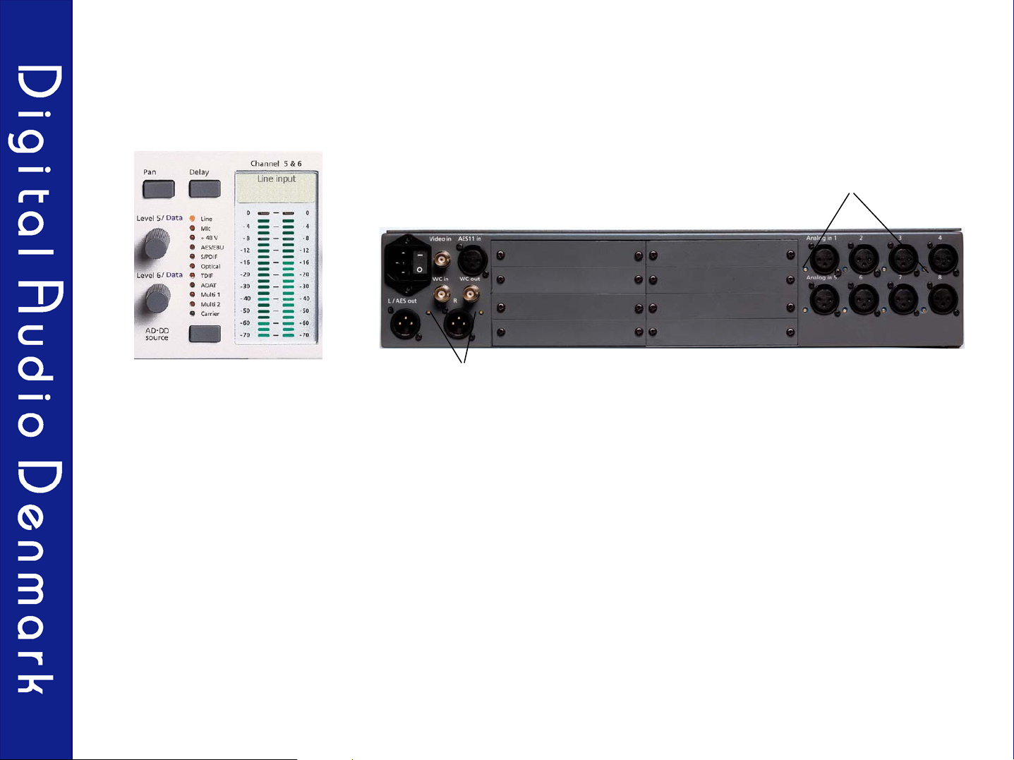
Connecting the cables
1. Place the unit on a dry surface or in a rack with plenty of space for ventilation.
2. Connect the analog cables
3. Connect the digital cables to the I/O modules and the sync cables.
4. Connect the power cord
Power cord Synchronisation Analog input 1-8
Analog stereo output or
AES
Digital and analog I/O slots for digital
I/O and analog outputs

4
Turn on the ADDA 2408
Turn on the power button on the front panel. For turning off the power you need to press
the button for about 3 sec.
Ensure that the main power switch is on

5
Basic structure
With the DA source button you select the source for the built in 8/2 mixer and for your
analog outputs. You can choose between the input selected on the AD-D button or any of
the digital interfaces. If a valid digital signal is present the green “Carrier” LED will light up.
If you have installed a ProTools Mix 24 compatible I/O card you have to choose this
interface as Multi 1 or Multi 2.
With the AD-D source button you can choose the input (for 2 channels at a time) which
will be availably as a digital signal on all digital multi-channel outputs with the sample-
rate, dither and sync selected at the sample-rate, dither and sync buttons.
If you choose an analog signal the converter will work as an A/D converter.
If you choose a digital signal the converter will work as a sample-rate and/or a format
converter. If the incoming digital signal is not in sync with the converter it will be detected
and the signal will be sample-rate converted.
If a valid digital signal is present the green ‘Carrier’ LED will light up.

6
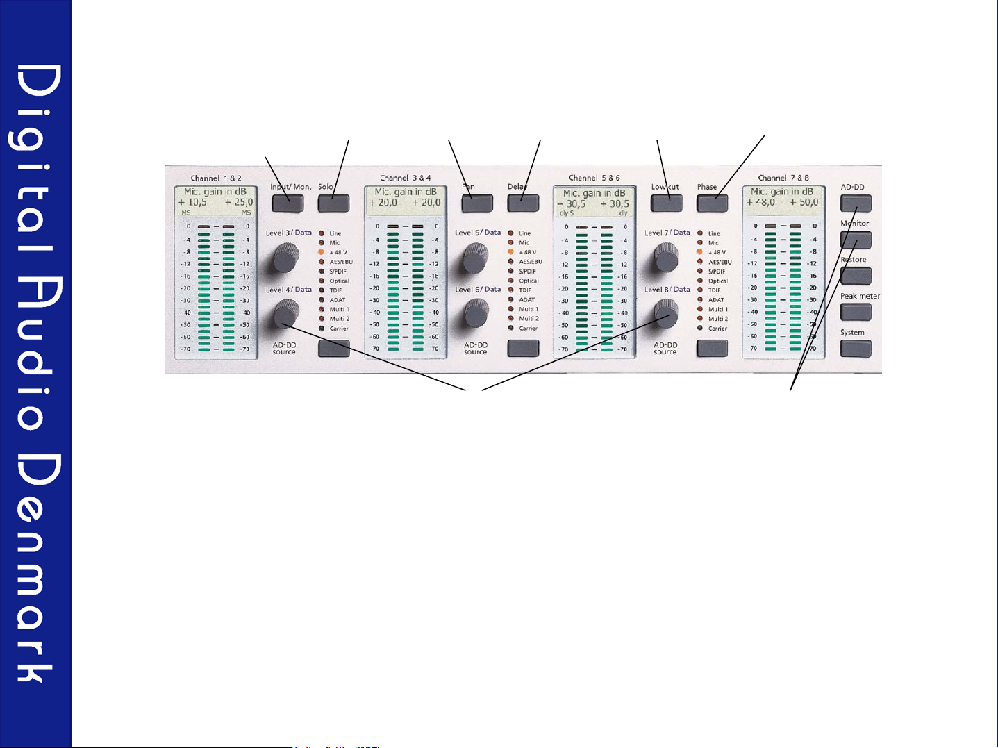
Overview
Power button with Security
locks, (the main power can
only be turned off by a
continuous 3 seconds
press on the power
button).
LCD display for all
stereo channels.
Short cuts button for
Input/monitor, Solo, Pan,
Delay, Low cut, and
Phase inversion.
Sample-rate,
sync and dither
buttons
DA source
button
Detailed 21 LED peak
metering measuring
the digital or analog
input.
A/D-D/A and
Systems button
High quality analog
headphone amplifier.
Level/data controls
for all 8 channels.
AD-D source button
for selection between
the analog or digital
inputs (2 channels
at the time)
The Level/data controls are used for all selections and adjustments. For adjustment of a
parameter related to a channel (1-8) use the corresponding Level/data controls. For adjustment
of an ‘over-all’ parameter use the Level/data controls and the LCD display for channels 7 & 8.
All primary functions are available by pressing only one button!
7
Short Cuts
Input/monitor
level
PhaseSolo Pan Delay Low cut
Level/data knobs for
the 8 channels
AD-DD and Monitor
menu
The short cut buttons provide fast access to the primary functions in the AD-DD and Monitor
menus.
The short cuts are only active when the short cut button is pressed. After releasing a short cut
button the ADDA 2408 returns to the function prior to short cut activation.
If for instance the Mic gain in dB is selected and a short cut is activated, the corresponding
function may be adjusted using the Level/Data knob for one or more channels. By releasing the
short cut button the ADDA 2408 returns to the Mic gain in dB function. It is therefore easy at all
times to identify the active functions of the ADDA 2408..
It is recommended to set the ADDA 2408 into Mic gain in dB or Monitor level mode while
recording.
8
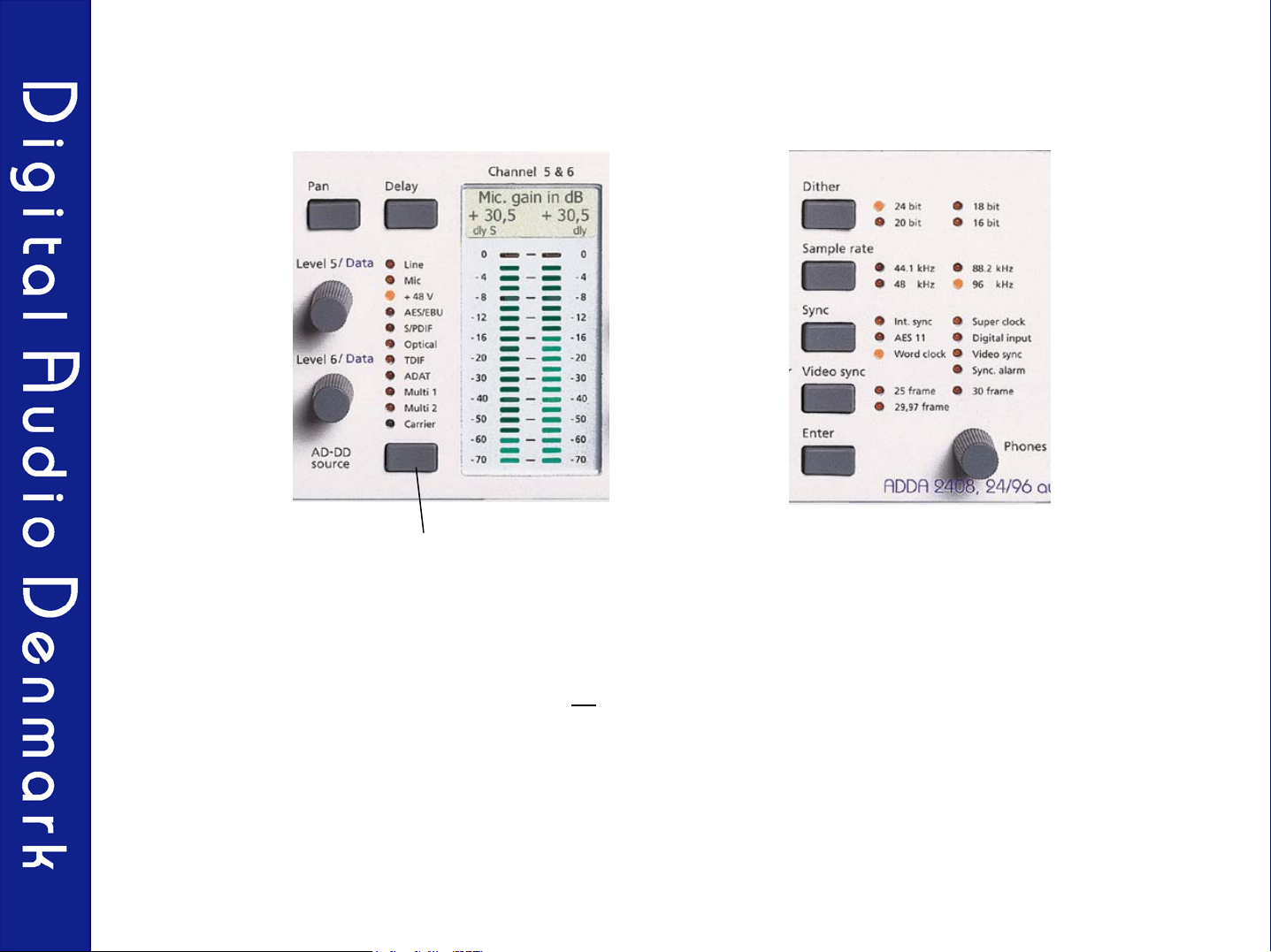
AD-DD Source Button
AD-D source button
With the AD-DD source button you can choose between the different analog or digital interfaces
for two channels at a time.
The selected input will be available on all digital outputs with the sample-rate, dither and
synchronization chosen at the Sample-rate, Dither and Sync buttons.
This way the unit can be either an A/D, a sample-rate, or a format converter between the digital
I/O’s mounted in the ADDA 2408.
If the selected digital input has a different sample-rate or synchronization than the sample-rate and
synchronization chosen at the Sample-rate and Sync buttons, the unit will auto-detect the
difference and use the built in sample-rate converter automatically.

9
World-Class Mic Preamp
Gain adjustment knobs for
all 8 channels
8 Ultra-High quality Mic Pre amps with phantom power, low cut filter and phase inversion.
The Mic Preamp itself has a very low equivalent input noise at - 130 dB at +24 dB gain.
Analog gain can be adjusted in increments of 3 dB. The following analog gain steps are
available: -18, - 12 , -6, - 3, 0, + 3, + 6, + 9, + 12, + 15, + 18, + 21, and + 24 dB of analog gain,
for at total of 42 dB analog gain adjustment.
This enables the user to scale any common microphone level properly into the 117dB dynamic
range provided by the A/D converter.
In between the analogue gain steps, the gain can be adjusted digitally in steps of 0.5 dB for a
maximum of +72 dB gain.
The maximum input level is 24 dBu.
The input impedance is 15 kΩallowing the Mic Preamps to handle line signals as well.

10
Synchronization Options
The Sync button
The ADDA 2408 accepts external synchronization from the following sources: AES11, Word Clock,
Video Clock or a digital input signal. If the digital input is selected as the sync source, it will be the
signal chosen at the DA source button which will also be used as the sync source.
It is recommended to use the internal synchronization of the ADDA 2408 or a master studio clock
of similar quality as the synchronization source for the ADDA 2408.
The frequency used for sampling will always be present as a Word Clock signal at the Word Clock
output. This way the ADDA 2408 can be used as a synchronization converter between AES11,
Video Clock, Digital input and Word Clock.
If a ProTools compatible I/O card is mounted in the ADDA 2408, synchronization can be set to
Super Clock input , (at the I/O card) and a Super Clock output will also be available.
A PLL circuit is cleaning up minor errors (jitter) in the incoming sync signal.
Because of the very precise internal oscillators (5ppm) the ADDA 2408 can be used as a studio
master sync generator.

11
Delay, Low cut and Phase
AD-DD menu
Lowcut shortcut
Delay shortcut Phase shortcut
Adjustment knobs for one or all 8 channels
A delay from 0 to 100 ms. can be added to all channels chosen at the AD-DD source button
separately.
Use the Delay short cut, or find the delay setting in the AD-DD menu.
The main application for the Delay setting is to bring a multi microphone set-up into correct
phase.
Another application is to set the delay of the audio signal to match the video delay when
mixing digital video.
Low-cut can be added to an analog signal on one or more channels. Use the Low cut shortcut
or find the Low-cut settings in the AD-DD menu.
Phase inversion can be added to all channels chosen at the AD-DD source button separately.
Use the Phase short-cut or find the Phase setting in the AD-DD menu.

12
The DA Source Button
DA source button
With the DA source button it is possible to choose the source for the D/A analog outputs.
Selection can be made between the outputs from the AD-DD converter, selected with the AD-
DD button or directly from one of the digital inputs.
The input chosen at the DA source button will be used as the source for the monitor mixer, and
if one or two expansion D/A cards are mounted in the ADDA 2408, the selected signal will be
present at these analog outputs as well.
If you want to use the ADDA 2408 for monitoring 5.1, you have to install one 4 channel D/A
expansion card. (Use the monitor mixer to route channel 5 and 6 to the analog stereo output.
The 4 channel D/A expansion card will monitor channels 1 to 4).

13
The Monitor Mixer
Solo shortcut Pan shortcut The Monitor menu button
The monitor Mixer can be used to mix down the 8 channels chosen at the DA Source button, into a
stereo mix.
At the Monitor mixer you can adjust output level, pan, solo, master level, solo level, and solo pre/post.
For two channels at a time (1/2, 3/4, 5/6, or/and 7/8) it is possible to chose between a normal L/R
output or a MS decoding of the signal. The level for M and S can be adjusted at the Level/Data knobs.
The output level, pan, and solo functions can be reached at the short cuts. The master level can be
adjusted at the Phones knobs.
The output from the monitor mixer will be available on the stereo XLR outputs on the back panel, and
the Phones output on the front panel.
It is possible to change the left analog XLR output on the back panel into a digital AES output in the
monitor menu.
The monitor output of two or more ADDA 2408’s can be linked together by connecting the AES output
from one ADDA 2408 to the AES 11 sync input of another ADDA 2408, and so on.

14
Head Phone Amp
A high quality analog headphone amplifier with 1/4 inch jack is located on the front panel. The
source for the headphone output is the stereo mix from the monitor mixer. The headphone
output level on the front panel and the stereo XLR line connectors on the back panel, may be
adjusted individually. However within the monitor menu it is possible to link the level of XLR
outputs on the back panel to the Phones level knob on the front panel
The head phone amplifier is powerful and capable of feeding up to 6 sets of 600 Ω
headphones with a high monitoring level.

15
Sync alarm
Sync alarm
The ADDA 2408 can detect if the converter is in correct synchronization with your hard disk
recording system. It is doing so by counting the incoming and outgoing samples on the digital
I/O cards.
If the connected hard disk recording system is not in sync with the converter, the sync alarm will
light up and the LED for the digital interface at the DA source will flash.
This can happen if both the converter and the hard disk recording system are set to internal
sync.

16
Overview: The Menu Structure
The Restore button:
Restores all AD-DD and
Monitor button settings
to default values
The AD-DD button:
Line, Mic Gain in dB, or Digital input
Low cut
Phase inversion
Delay
The Monitor button:
Monitor Level in dB
Monitor pan
Monitor Solo
L/R or MS listening
Master Level /dB
Solo Level /dB
Solo Pre/Post
L/R or AES
Link L/R level to Phones
The Peak meter button:
AD-D source/DA source
Peak hold on/off
The System button:
Recall preset
Store preset
Delete preset
Display contrast
I/O options
Clock sync output
Sync alarm on/off
Max Line level
Use the level/Data knobs for channel
7 & 8 and the Enter button in order to
change the settings in the different
menu's.
The LCD display for Channels 7 & 8
will show the settings for the different
menu settings.
17
Precise Line Level Adjustment
Line level adjustment knobs
for all 8 input channels
Line level adjustment knobs
for stereo analog output
The output line level can be adjusted on the back panel to a reference level for 0 dBFS
between + 12 and + 27 dBu.
The input line level is set in the System menu between +12 and +21 or +21 and 30 dBu.
Precise adjustment is done at the line level adjustment knobs on the back panel.
If another analog input level is required, the Mic input can be selected, since this input will
accept line levels as well.

18
I/O modules
A variety of expantion cards can be added to the ADDA 2408, including:
* Dual AES3-S/PDIF digital I/O
* 8 ch. AES3 digital I/O
* 8 ch. TDIF digital I/O
* 8 ch. ProTools Mix 24 compatible I/O
* 8 ch. ADAT SMUX compatible I/O
* 4 ch. D/A converter

19
The 4 ch. DA converter interface
1. One or two DA interfaces can be mounted in the ADDA 2408 for additional 4 or 8 ch.of analog
outputs. The DADI/O-4DAC-XLR or the DADI/O-4DAC-XLR-L. On both cards the output line level
can be adjusted to a reference level for 0 dBFS between + 12 and + 27 dBu via individual
potentiometers on the modules.
2. The DADI/O-4DAC-XLR can monitor the AD-DD source or the DA source. It also has build in output
level control which can be set to individual levels for all channels and with a master level controled via
the headphone knob. Together with the 2 stereo outputs already in the ADDA 2408 one DADI/O-
4DAC-XLR can be used as monitor output with output level control for 5.1 applications.
3. The DADI/O-4DAC-XLR-L can only monitor the digital inputs. The output level can not be controled.
One or two DADI/O-4DAC-XLR-L can be mounted in the ADDA 2408 for 4 or 8 ch. of analog outputs.
.

20
The ProTools Mix 24 compatible I/O’s.
1. If a ProTools compatible interface is mounted in the ADDA 2408 you can connect this interface on the
ADDA 2408 directly to the computer, the same way you normally connect your 888/24 I/O's.
2. Turn on the power on the ADDA 2408. Then start the ProTools system.
3. In the Hardware set-up menu of the ProTools system the ADDA 2408 is showing itself as an 888 /24
interface, and has to be set up as an 888 /24 interface. However the ADDA 2408 (888 /24 ) has to be set
to internal sync in the ProTools menu. At the ADDA 2408 the ProTools interface will be identified as multi
1 or multi 2.
4. The sync source for the ADDA 2408 must be chosen on the front panel of the ADDA 2408.
5. Generally we recommend the ADDA 2408 as the master clock generator, because of its much more
accurate oscillators (5ppm) compared to most units.
6. We also recommend Word Clock instead of Super Clock where possible, because Super Clock is 256
times faster than Word Clock and therefore more sensitive to Jitter.
7. On the ProTools Mix 24 compatible interface you will also find two BNC connectors called ‘In’ and ‘Out’.
These connectors are for Super Clock in/out. If you want to synchronize the ADDA 2408 via Super
Clock, connect a valid Super Clock signal to In and choose Super Clock at the Sync button on the front
panel. If you want to synchronize an 888 I/O or USD from the ADDA 2408, connect the Super Clock
input on one of these units to the Super Clock out at the ProTools Mix 24 compatible interface mounted
in the ADDA 2408.
.
Table of contents
Other Digital audio Media Converter manuals


