AutomationDirect IronHorse GSDA-DP-S User manual

Page 1
IronHorse GSDA-DP-S User Manual – 1st Edition – 09/18/2019
™
GSDA-DP-S SiGnAl ConDitioner/GenerAtor USer MAnUAl
User ManUal nUMber: GsDa-DP-s_UMP
NOTE: (table)

Page 2 IronHorse GSDA-DP-S User Manual – 1st Edition – 09/18/2019
WArninG
Thank you for purchasing automation equipment from Automationdirect.com®, doing business as
AutomationDirect. We want your new automation equipment to operate safely. Anyone who installs or uses
this equipment should read this publication (and any other relevant publications) before installing or operating
the equipment.
To minimize the risk of potential safety problems, you should follow all applicable local and national codes
that regulate the installation and operation of your equipment. These codes vary from area to area and usually
change with time. It is your responsibility to determine which codes should be followed, and to verify that the
equipment, installation, and operation is in compliance with the latest revision of these codes.
At a minimum, you should follow all applicable sections of the National Fire Code, National Electrical Code,
and the codes of the National Electrical Manufacturer’s Association (NEMA). There may be local regulatory or
government offices that can also help determine which codes and standards are necessary for safe installation
and operation.
Equipment damage or serious injury to personnel can result from the failure to follow all applicable codes and
standards. We do not guarantee the products described in this publication are suitable for your particular
application, nor do we assume any responsibility for your product design, installation, or operation.
Our products are not fault-tolerant and are not designed, manufactured or intended for use or resale as on-line
control equipment in hazardous environments requiring fail-safe performance, such as in the operation of
nuclear facilities, aircraft navigation or communication systems, air traffic control, direct life support machines,
or weapons systems, in which the failure of the product could lead directly to death, personal injury, or severe
physical or environmental damage (“High Risk Activities”). AutomationDirect specifically disclaims any
expressed or implied warranty of fitness for High Risk Activities.
For additional warranty and safety information, see the Terms and Conditions section of our catalog. If you have
any questions concerning the installation or operation of this equipment, or if you need additional information,
please call us at 770-844-4200.
This publication is based on information that was available at the time it was printed. At AutomationDirect we
constantly strive to improve our products and services, so we reserve the right to make changes to the products
and/or publications at any time without notice and without any obligation. This publication may also discuss
features that may not be available in certain revisions of the product.
trADeMArkS
This publication may contain references to products produced and/or offered by other companies. The product
andcompanynamesmaybetrademarked and arethesolepropertyoftheirrespectiveowners. AutomationDirect
disclaims any proprietary interest in the marks and names of others.
Copyright©2019 Automationdirect.com® Incorporated
All Rights Reserved
No part of this manual shall be copied, reproduced, or transmitted in any way without the prior, written consent
of Automationdirect.com® Incorporated. AutomationDirect retains the exclusive rights to all information
included in this document.
PUbliCAtion HiStory
User Manual Publication History
Issue Date Description
First Edition 09/18/19 Initial release
~ ~

Page 3
IronHorse GSDA-DP-S User Manual – 1st Edition – 09/18/2019
ContentS
Warning � � � � � � � � � � � � � � � � � � � � � � � � � � � � � � � � � � � � � � � � � � � � � � � � � � � � 2
Trademarks� � � � � � � � � � � � � � � � � � � � � � � � � � � � � � � � � � � � � � � � � � � � � � � � � � � 2
Publication History � � � � � � � � � � � � � � � � � � � � � � � � � � � � � � � � � � � � � � � � � � � � � � 2
GSDA-DP-S User Manual Overview � � � � � � � � � � � � � � � � � � � � � � � � � � � � � � � � � � � � � 4
IronHorse GSDA-DP-S General Information� � � � � � � � � � � � � � � � � � � � � � � � � � � � � � � � � 4
GSDA-DP-S Installation � � � � � � � � � � � � � � � � � � � � � � � � � � � � � � � � � � � � � � � � � � � � 6
GSDA-DP-S Operation � � � � � � � � � � � � � � � � � � � � � � � � � � � � � � � � � � � � � � � � � � � � 8
Device Configuration � � � � � � � � � � � � � � � � � � � � � � � � � � � � � � � � � � � � � � � � � � � � � 9
Software Parameters � � � � � � � � � � � � � � � � � � � � � � � � � � � � � � � � � � � � � � � � � � � � 11
Troubleshooting � � � � � � � � � � � � � � � � � � � � � � � � � � � � � � � � � � � � � � � � � � � � � � � 16

Page 4 IronHorse GSDA-DP-S User Manual – 1st Edition – 09/18/2019
GSDA-DP-S USer MAnUAl overvieW
Overview Of this PUblicatiOn
The IronHorse GSDA-DP-S User Manual describes the installation, configuration, and methods of
operation of the GSDA-DP-S Signal Conditioner/Generator.
All information contained in this manual is intended to be correct. However, information and data
in this manual are subject to change without notice. AutomationDirect (ADC) makes no warranty of
any kind with regard to this information or data. Further, ADC is not responsible for any omissions or
errors or consequential damage caused by the user of the product. ADC reserves the right to make
manufacturing changes which may not be included in this manual.
whO shOUlD reaD this User ManUal
This manual contains important information for those who will install, maintain, and/or operate the
GSDA-DP-S Signal Conditioner/Generator.
technical sUPPOrt
bytelePhOne: 800-633-0405 (MOn.–fri., 9:00 a.M.–6:00 P.M. e.t.)
Onthe web: www.aUtOMatiOnDirect.cOM
Our technical support group is glad to work with you in answering your questions. If you cannot
find the solution to your particular application, or, if for any reason you need additional technical
assistance, please call Technical Support at 800-633-0405. We are available weekdays from 9:00 a.m.
to 6:00 p.m. Eastern Time.
We also encourage you to visit our web site where you can find technical and non-technical
information about our products and our company. Visit us at www.automationdirect.com.
sPecial syMbOls
NOTE: When you see the “notepad” icon in the left-hand margin, the paragraph to its immediate
right will be a special note.
WARNING: WheN you see the “exclAmAtIoN mARk” IcoN IN the left-hANd mARGIN, the pARAGRAph to Its ImmedIAte
RIGht WIll be AWARNING. thIs INfoRmAtIoN could pReveNt INjuRy, loss of pRopeRty, oR eveN deAth (IN extReme
cAses).
ironHorSe GSDA-DP-S GenerAl inforMAtion
The GSDA-DP-S is a panel mounted, multi-purpose signal conditioner that allows the operator easy
access to make adjustments to system operations. The GSDA-DP-S may be used in OEM equipment
designs, plant operation or laboratory applications. Most other signal conditioners are DIN rail
mounted inside a panel and designed to be set up once - many applications require frequent
adjustments to meet application needs. The unique front-panel design of the GSDA-DP-S addresses
this by making output adjustment easily accessible via convenient up and down pushbuttons and a
large, easy to read LED display.
stanDarD featUres
•
Microprocessor design digital accuracy and repeatability
•
Digital design offers long-term stability in a variety of environments
•
Dual-Mode operation: Signal Scaling, or Signal Generation
•
Works in either voltage or current output modes
•
Universal power supply accepts voltages of 85-265VAC@50-60Hz without switches or jumper settings�
•
Transient voltage protection protects device in harsh industrial environments
•
1/8 DIN panel mount is rated up to NEMA 4X in similarly rated panel
•
Large 4 digit, 1/2” LED display is easy to read in indoor or outdoor applications
•
Euro style terminal strip standard - pluggable terminal strip optional
•
Wide operating temperature -10°C to +45°C (14°F to 113°F)
•
Jumper selectable signal type - Voltage or Current (mA) signal
•
Configurable input to lock out operator changes once set

Page 5
IronHorse GSDA-DP-S User Manual – 1st Edition – 09/18/2019
warranty
AutomationDirect, Inc. (ADC) warrants its products to be free from defects in material and
workmanship. The exclusive remedy for this warranty is ADC factory replacement of any part or parts
of such product which shall within 12 months after delivery to the purchaser be returned to ADC
factory with all transportation charges prepaid and which ADC determines to its satisfaction to be
defective. This warranty shall not extend to defects in assembly by other than ADC or to any article
which has been repaired or altered by other than ADC or to any article which ADC determines has been
subjected to improper use. ADC assumes no responsibility for the design characteristics of any unit
or its operation in any circuit or assembly. This warranty is in lieu of all other warranties, express or
implied; all other liabilities or obligations on the part of ADC, including consequential damages, are
hereby expressly excluded.
NOTE: Carefully check the GSDA-DP-S for shipping damage. Report any damage to the carrier
immediately. Do not attempt to install the device if visible damage is evident to either the circuit or
to the electronic components..
sPecificatiOns
GSDA-DP-S Specifications
Electrical
Line Input Voltage 85-265 VAC
Line Input Frequency 48-62 Hz
Voltage Signal Input 0-10 VDC
Voltage Signal Output Min: 0�1-5 VDC
Max: 0�1-20 VDC, 10mA
mA Signal Input 4-20 mA
mA Signal Output 4-20 mA
Display Range Default: 0-100�0%
Max: -9999 – 9999
Units of Operation Programmable
Onboard Power Supply (Externally Accessible) 5V @ 500mA
Voltage Regulated Supply Output Range 24VDC ± 5%, 200mA
Mechanical
Display Type LED, red, 4 digit, 1/2” height
Housing Type (with supplied gasked in NEMA
4X panel) 1/8” DIN NEMA 4X
Connector Style 3�5mm and 5mm European style
Terminus Block Torque Setting 4�4 in-lb [0�5 Nm] maximum
Faceplate Material Polycarbonate with Lexan overlay
Housing Material Aluminum
Length (Required Panel Depth) 4�625” [117�48 mm]
Faceplate Width 4�539” [115�29 mm]
Weight 14�4 oz [408�22g]
Environmental
Operating Temperature Range -10°C to 45°C [14°F to 113°F]
Operating Humidity Range 95%, non-condensing

Page 6 IronHorse GSDA-DP-S User Manual – 1st Edition – 09/18/2019
GSDA-DP-S inStAllAtion
installatiOn Of GsDa-DP-s
PANEL MOUNTING GASKET
(WITH THE ADHESIVE SIDE OF
GASKET FACING THE CUSTOMER
MOUNTING PANEL)
CUSTOMER
MOUNTING PANEL
(HOLE CUT-OUT FOR CONTROL
HOUSING APPROXIMATELY
3.622" WIDE BY 1.770" HIGH)
GSDA-DP-S
CONTROL
SUPPLIED WITH EACH CONTROL:
1) GASKET
2) (2) 6-32 X 3/4 PANHEAD BLACK OXIDE STAINLESS SCREWS
3) (2) #6 NUT WITH LOCKWASHER
Exploded Panel View
cUt-OUt anD MOUntinG DiMensiOns
HOUSING DEPTH
4.625 [117.5]
PANEL CUT-OUT
GSDA-DP-S
x 2
GEN
SCL SPL
ENTER
SIGNAL SCALER
AND GENERATOR
4.00
[101.6] 3.62
[91.9]
0.885 [22.5]
1.77 [45.0]
.140
[3.6]
4.00
[101.6]
5.00
[127.0]
4.625
[117.5]
2.289
[58.1]
1.656
[42.1]
Page 7
IronHorse GSDA-DP-S User Manual – 1st Edition – 09/18/2019
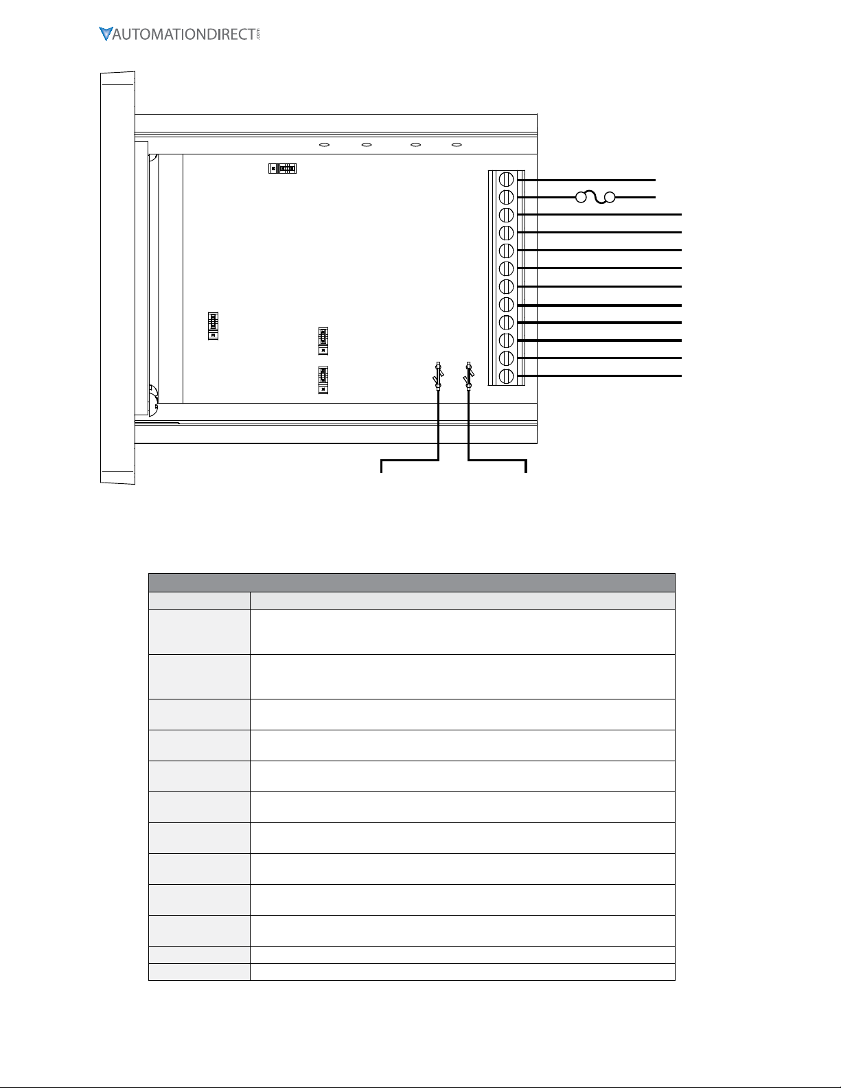
P3 terMinal blOck hOOk-UPDiaGraM
AC INPUT
AC INPUT
P3-1
P3-2
P3-3
P3-4
P3-5
P3-6
P3-7
P3-8
GSDA-DP-S
2 AMP
P3-9
P3-10
P3-11
P3-12
}85-265VAC
N
L
+5V
COM
IN2
IN1
4-20 OUT (+)
4-20 OUT (-)
V-OUT (+)
V-OUT (-)
SIGNAL IN (+)
SIGNAL IN (-)
+V_USER
-V_USER
+24VDC SUPPLY -24VDC SUPPLY
}
OUTPUT TO USER DEVICE
JP5
JP4
JP3
JP1
P3 terMinal blOck DescriPtiOns
Terminal Block Descriptions
Terminal Description
P3-1
(AC / N) – For single phase AC lines connect the Neutral side of your AC line to
this terminal� For systems with two hot AC lines, connect either of the Hot AC
lines to this terminal�
P3-2
(AC / L) – For single phase AC lines connect the Hot side of your AC line to this
terminal� For systems with two hot AC lines, connect either of the Hot AC lines to
this terminal�
P3-3 (-SIGNAL IN) – In Scaled Mode, connects to Negative or Common of voltage or
current signal to be attenuated�
P3-4 (+SIGNAL IN) – In Scaled Mode, connects to Positive of voltage or current signal
to be attenuated�
P3-5 (-24VDC SUPPLY) – A 24VDC supply output is provided to the user for sensor or
other device�
P3-6 (+24VDC SUPPLY) – A 24VDC supply output is provided to the user for sensor or
other device�
P3-7 (-mA OUTPUT) – The negative connection for either Scaled or Generated mA
current output signal�
P3-8 (+mA OUTPUT) – The Positive connection for either Scaled or Generated mA
current output signal�
P3-9 IN1 - Contact input for user configurable actions such as specified output, and
set point lock�
P3-10 IN2 - Contact input for user configurable actions such as specified output, and
set point lock�
P3-11 COM
P3-12 +5V

Page 8 IronHorse GSDA-DP-S User Manual – 1st Edition – 09/18/2019
GSDA-DP-S oPerAtion
The GSDA-DP-S Signal Conditioner is a panel-mounted multiple function device used to either
attenuate (scale or reduce), convert, or generate control signals typically used in laboratory/R&D or
plant/industrial applications. The input signals are analog in nature and specifically in the 0-10 VDC or
4-20 mA range. The output signal can be either 4-20mA or from 0.1 VDC to the Vset voltage (5-20 VDC).
visUal reference
GEN
SCL SPL
ENTER
SIGNAL SCALER
AND GENERATOR
ENTER (Select) Button
Up & Down Buttons
Display Window
The Up/Down buttons are used to Scale or Set the output level, in percent (default). The Minimum
Scaling/Generator output is 0.0%. The Maximum Scaling/Generator output is 100.0%. On power up,
the factory default setting is “Last Value”.
When lit, the annunciator LED’s across the top of the GSDA-DP-S indicate the following:
•
SCL: Scaling mode is active and device output will be either voltage or current, depending on the
jumper configuration� In current output mode the display setting and the input current or voltage
determine the 4-20mA output level� In voltage output mode the display setting, the maximum level
set by the potentiometer R9 adjustment and the input current or voltage determine the output
voltage level; see “Device Configuration” for proper hardware and software setup�
•
Gen: Generate mode is active and device output will be either voltage or current, depending on
the jumper configuration� In current output mode only the display setting effects the 4-20mA
current output level� In voltage output mode, the display setting and the maximum level set by the
potentiometer R9 adjustment determine the voltage output level; see “Device Configuration” for
proper hardware and software setup�
•
SPL: The GSDA-DP-S is in Set Point Lock; this effectively disables any changes until IN1/IN2 input
levels change according to the functional configurations� Various modes are available with SPL, please
see parameters 30, 31, 35 and 36, which can be used to configure Set Point Lock�
hOw tO chanGe aParaMeter’svalUe
1) Hold down the Enter button until Parameter Mode is entered (parameter ‘P 0’ Displayed)
2) Using the Up and Down buttons, select the desired parameter number to view or edit
3) Press the Enter button to change the value of the parameter
4) Using the Up and Down buttons, change the parameter’s value as desired
5) Press the Enter button to permanently save the changes (Return to Parameter-Selection Mode)
6) Select parameter zero and press the Enter button to return to Running Mode
OPeratinG the User interface
The LED display has three basic operating modes: Run Mode, Parameter Mode, and Value Mode. Each
of the three modes have specific visual indicators that allow the user to immediately determine the
current state or mode of the user interface. Parameter Mode and Value Mode can only be entered if
the Program Enable jumper is in the ‘P/EN’ position.
Run mode is the default display of the unit when power is applied. The display shows the target value
in the appropriate user-defined format. The Up and Down buttons increase or decrease the displayed
target value until either the display minimum or display maximum limit is reached.

Page 9
IronHorse GSDA-DP-S User Manual – 1st Edition – 09/18/2019
Parameter Mode can be entered by simply pressing and holding the Enter button down for three
seconds. Once in Parameter Mode, the far left of the display will be a ‘P’. The right side of the display
will indicate the currently selected parameter number for editing purposes. Pressing the Up or
Down button will increase or decrease the selected parameter number on the display. Although the
parameter numbers are in numerical order, some numbers are skipped. These skipped numbers
represent reserved parameters that are not yet implemented and are not displayed. Once the desired
parameter number is displayed, pressing the Enter button will change the display to Value Mode.
Value Mode is used to modify the value of the selected parameter. When in Value Mode, the two
dots which form the colon between digits two and three, will alternately flash (one, then the other.)
Pressing the Up or Down button increases or decreases the selected parameter’s value. See the
Software Parameters for a list of allowable values and ranges. Value changes take effect immediately.
Once the desired value is showing in the display window, pressing the Enter button again will return to
Parameter Mode. The new value is not saved in permanent memory until the Enter button is pressed.
Removing power from the unit while in Value Mode may result in the specified new value being lost.
The front panel Annunciators will be perform as follows:
•
Parameter 10 = 1; ‘Gen’ annunciator lit
•
Parameter 10 = 2; ‘SCL’ annunciator lit
•
Parameter 30 = 7, IN1 = Low; ‘SCL’ annunciator lit
•
Parameter 35 = 7, IN2 = High; ‘SCL’ annunciator lit
DeviCe ConfiGUrAtion
Configuration is accomplished via jumper settings and (for Voltage Outputs only) a trimpot
adjustment. Location is as follows:
P3
Program Enable
(JP5)
VOUT/4-20mA
Jumper 4 (JP4)
VOUT/4-20mA
Jumper 3 (JP3)
P5 P6
JP1
Trimpot
(R9)
I_IN V_IN
COM P/EN
V_OUT
I_OUT
V_OUT
I_OUT
With the display set to 100.0 and no user device connected to ‘V-OUT’, P3-5 (-) and P3-6(+), adjust R9
for the desired maximum V-OUT. Finally, connect the user device and carefully re-adjust R9 to trim
the output to desired maximum V-OUT. This will prevent the output from exceeding the limits of the
user device if done properly. The user should evaluate what their system will be doing during this
adjustment to prevent any harmful results.
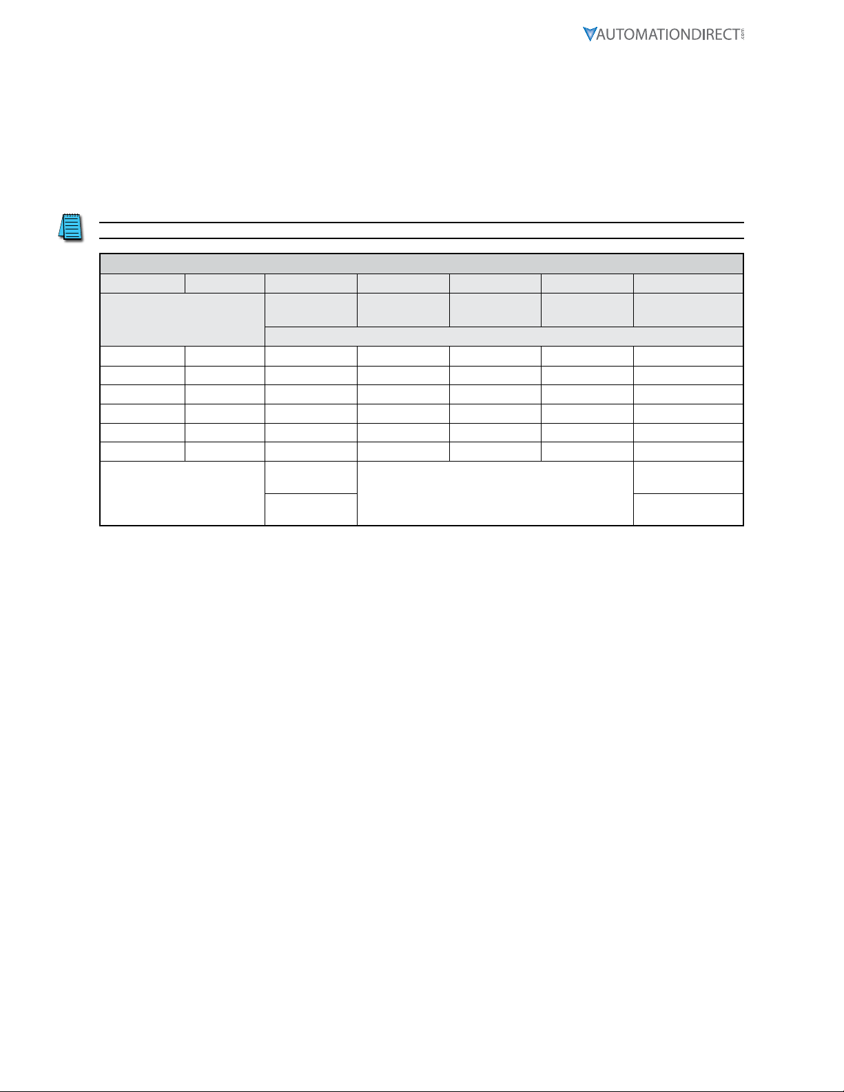
MODe Of OPeratiOn
There are three Modes of Operation for the GSDA-DP-S, established by the JP1, JP3, and JP4 jumper
settings:
Page 10 IronHorse GSDA-DP-S User Manual – 1st Edition – 09/18/2019
1) JP1 - If the GSDA-DP-S is receiving a signal to be Scaled or Converted, this setting defines the
input signal type (0-10 VDC or 4-20 mA Current).
2) JP3 and JP4 - Determine the Output Signal type - Vdc or Current (4-20 mA). Both JP3 and JP4
MUST be set the same.
The four jumper settings allow the GSDA-DP-S to operate as:
1) 4-20 mA Input/Scaled 4-20 mA or 0.1-20VDC Output
2) 0-10 VDC Input/Scaled 4-20 mA or 0.1-20VDC Output
3) No Input/Generator 4-20 mA or 0.1-20VDC Output
NOTE: Both JP3 and JP4 must be set the same.
GSDA-DP-S Current/Voltage I/O Jumpers and Parameter 10 Settings
Input Output Parameter 10 JP1 JP3 JP4 JP5
Scale/
Generate
V/I In V/I Out
Reference
V/I Out Power
Supply
Application
Configuration
Pin to Pin Jumper Configuration
Current Voltage Scale li Vo Vo
Current Current Scale li Io Io
Voltage Voltage Scale Vi Vo Vo
Voltage Current Scale Vi Io Io
Generate Voltage Gen N/A Vo Vo
Generate Current Gen N/A Io Io
Scale = 2 Allow Change = P/
EN position
Gen = 1 Inhibit Change =
‘COM’ position

Page 11
IronHorse GSDA-DP-S User Manual – 1st Edition – 09/18/2019
SoftWAre PArAMeterS
Parameter Description Value Range Units Default
0Select parameter 0 to return to Run
mode n/a – n/a
Read-Only Parameters
1 Model Number 90 – GSDA-DP-S 90
2 Software Build 1–9999 n/a
3 Hardware Version 1–9999 n/a
4 Serial Number - Major (Reserved) n/a n/a
5 Serial Number - Minor (Reserved) n/a n/a
General Setup Parameters
10 Generate/Scale 1–Generate
2–Scale 1
11 Display Intensity 0–31 (Dim–Bright) 26
12 Display Zero Blanking
1–___X Show at least 1 digit
2–__XX Show at least 2 digits
3–_XXX Show at least 3 digits
4–XXXX Show at least 4 digits
2
13 Decimal Point Position
0–Decimals Disabled (XXXX)
1–X�XXX
2–XX�XX
3–XXX�X
4–XXXX�
3
15 Keypad Mode 1–Linear, constant rate
2–Non-linear, accelerating rate 2
16 Keypad Scroll Delay 0–30 (Fast–Slow) 10
18 Power-Up Mode
1–Default to Zero Display
2–Default to Power-up Value
3–Default to Previous Running
Value
3
19 Power-Up Value 0–9999 (Eng�
Units) 0
Display and Output Setup Parameters
20 Display Value at Minimum Output -9999–9999 (Eng�
Units) 0
21 Display Value at Maximum Output -9999–9999 (Eng�
Units) 1000
25 Output % - Minimum 0–1000 1/10 % 0
26 Output % - Maximum 0–1000 1/10 % 1000
Input #1 (IN1) Setup Parameters
30 IN1 Input Configuration
1–Output 0% when IN1 Low
2–Output 0% when IN1 High
3–Output Setpoint when IN1 Low
4–Output Setpoint when IN1 High
5–Output 100% when IN1 Low
6–Output 100% when IN1 High
7–Lock Set Point when IN1 Low
1
31 IN1 Setpoint -9999–9999 (Eng�
Units) 0
Input #2 (IN2) Setup Parameters
35 IN2 Input Configuration
1–Output 0% when IN2 Low
2–Output 0% when IN2 High
3–Output Setpoint when IN2 Low
4–Output Setpoint when IN2 High
5–Output 100% when IN2 Low
6–Output 100% when IN2 High
7–Lock Set Point when IN2 High
1
36 IN2 Setpoint -9999–9999 (Eng�
Units) 0
Parameter Memory Commands
95 Restore Settings to Factory Default 0–Do Nothing and Exit
5–Restore Factory Defaults 0
Page 12 IronHorse GSDA-DP-S User Manual – 1st Edition – 09/18/2019
Parameter Description Value Range Units Default
98 Save to User Default Area 0–Do Nothing and Exit
1–Save Settings 0
99 Restore from User Default Area 0–Do Nothing and Exit
1–Restore Settings 0
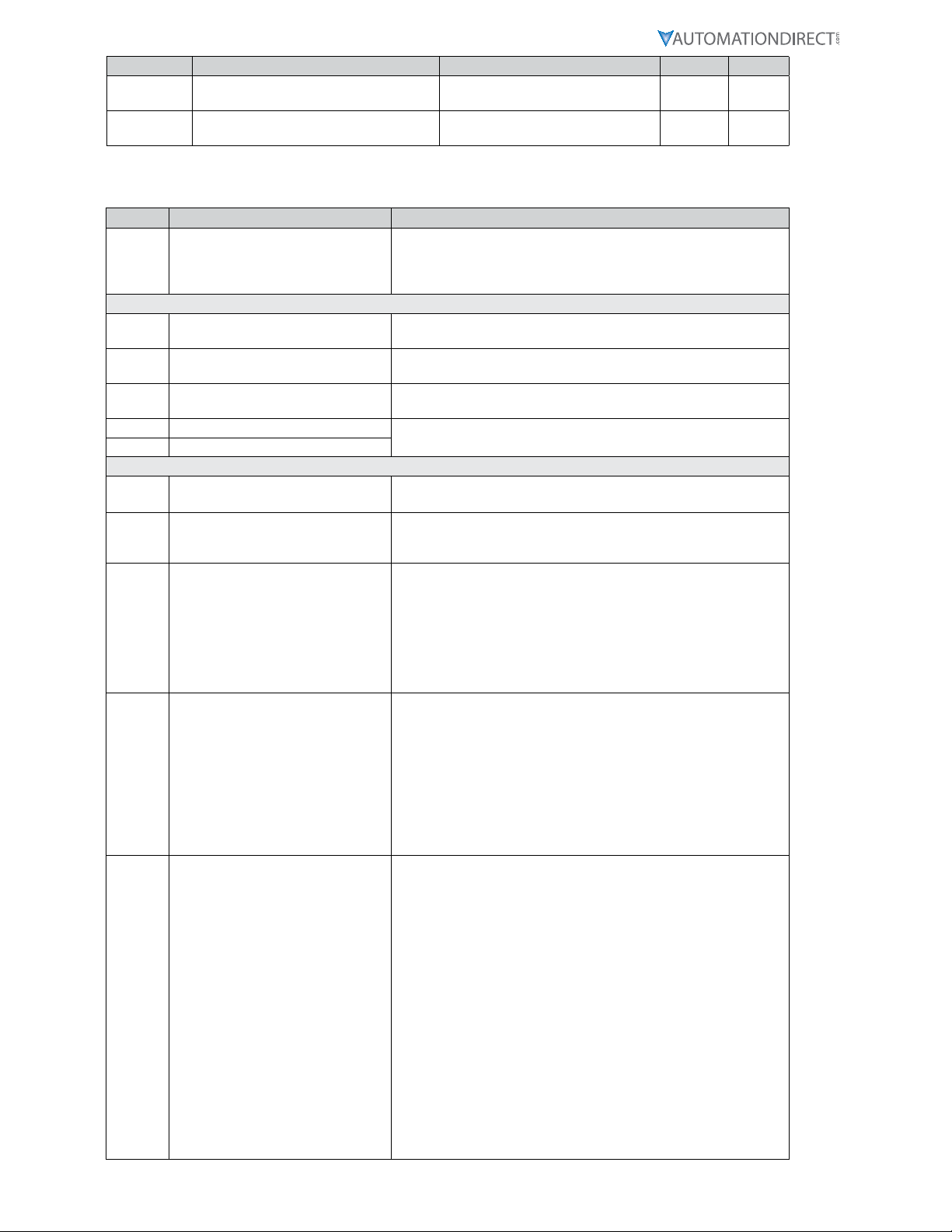
ParaMeter DescriPtiOns
Item Parameter Name Description
0 Exit to Running Mode
When parameter 0 is selected in Parameter-Selection Mode, the
unit will return to Running Mode and display the running value�
This should be selected once the changes to the parameters are
completed�
Read-Only Identification Items
1 Model Number This is a number which represents the base model number for the
product� The model code for the GSDA-DP-S is 90�
2 Software Build The software build is a code which identifies the software version
of the unit�
3 Hardware Version The hardware version is a code which identifies which hardware
was used to build the unit�
4 Serial Number - Major (Reserved) These parameters are reserved for future use as an electronic serial
number and are unique to each manufactured unit�
5 Serial Number - Minor (Reserved)
General Setup
10 Generate/Scale Mode 1: Generate–Generate Output Signal
Mode 2: Scale–Scale Input Signal
11 Display Intensity
This parameter adjusts the intensity of the LED display digits in
the front panel of the unit� The values of 0 – 31 correspond to a
gradual change from very dim to very bright�
12 Display Zero Blanking
This selects the number of display digits that are required to be
displayed regardless of the display value� For example, with a
Display Zero Blanking setting of 3 and a displayed value of 6, the
display would show “_006”�
• Mode 1: ___X Always show at least 1 digit
• Mode 2: __XX Always show at least 2 digits
• Mode 3: _XXX Always show at least 3 digits
• Mode 4: XXXX Always show all 4 digits
13 Decimal Point Position
This selects the format of the display with respect to the decimal
point’s position� This parameter does not affect the value entry
for other parameters� For example, if the user desires to display
numbers such as 12�34 or 1�05, then parameter 13 should be set
to 2�
• Mode 0: Fixed XXXX (DP disabled)
• Mode 1: Fixed X�XXX
• Mode 2: Fixed XX�XX
• Mode 3: Fixed XXX�X
• Mode 4: Fixed XXXX�
15 Keypad Mode
This parameter selects the operating mode of the front-panel push
buttons� In some applications, increasing or decreasing the scroll
rate provides the user more controllability when entering settings�
Parameters 14 and 15 affect only the Up and Down buttons when
the user interface is in Running Mode�
• Mode 1: Linear, Constant Rate
In linear mode, pressing and holding the Up or Down buttons
will cause the display to continuously change value in the
requested direction until either the Display Minimum or Display
Maximum is reached� The displayed value will scroll at a
constant rate which is specified using parameter 16�
• Mode 2: Non-linear, Accelerating Rate
In non-linear mode, pressing and holding the Up or Down
buttons will cause the display to continuously change value in
the requested direction until either the Display Minimum or
Display Maximum is reached� The displayed value will initially
scroll at a slow rate and increase in speed until the maximum
scroll rate is achieved� The initial scroll rate is specified using
parameter 16�
Page 13
IronHorse GSDA-DP-S User Manual – 1st Edition – 09/18/2019
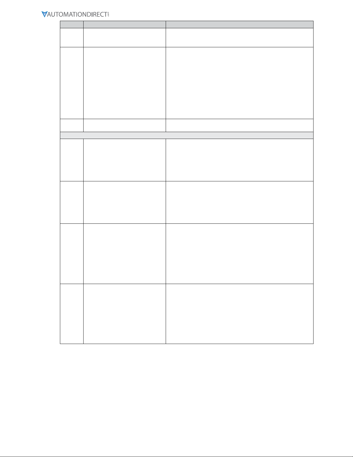
Item Parameter Name Description
16 Keypad Scroll Delay
This parameter sets the scroll speed for the front-panel push
buttons� The function of this parameter varies slightly depending
on the Keypad Mode� See parameter 15 for more details�
18 Power-Up Mode
This parameter defines the mode which determines the default
Running Value when power is initially applied to the GSDA-DP-S�
• Mode 1: Default to Zero
When in this mode, the unit will default to zero (display units)�
• Mode 2: Default to Power-Up Value
When in this mode, the unit will default to the Power-up Value,
parameter 19�
• Mode 3: Default to Previously Running Value
When in this mode, the unit will default to the previous running
value before power was removed� A previous running value
must have been active for at least 3 seconds to be recalled after
power has been disconnected and reapplied�
19 Power-Up Value When Power-up Mode is set to 2, this parameter will designate the
default display value at power-up in display units�
Display and Output Setup
20 Display Value at Minimum Output
This parameter defines the lower end of the display range� This
is the value which limits how low the user is able to scroll the
displayed value in Running Mode� This parameter is set without
consideration for the decimal point’s position� For example,
setting this parameter to 125 would set the lower display limit
at 12�5, 0�125, or 125 according to the other configuration
parameters�
21 Display Value at Maximum Output
This parameter defines the upper end of the display range� This
is the value which limits how high the user is able to scroll the
displayed value in Running Mode� This parameter is set without
consideration for the decimal point’s position� For example,
setting this parameter to 1000 would set the upper display limit
at 100�0, 1�000, or 1000 according to the other configuration
parameters�
25 Output % - Minimum
(in 1/10 percent units)
This parameter sets the output percentage which corresponds to
the minimum display value, parameter 20� This parameter has
a range of 0 to 1000 which represents 0�0 to +100�0 percent of
output� When the user is adjusting the display value towards the
programmed minimum display, the output will linearly approach
the value of this parameter� For example, setting this parameter
to 25 will configure the GSDA-DP-S to output 2�5% when the user
adjusts the display value to equal the display minimum, parameter
20� See parameters 20 - 22 and the application examples for
additional information�
26 Output % - Maximum
(in 1/10 percent units)
This parameter sets the output percentage which corresponds to
the maximum display value, parameter 21� This parameter has
a range of 0 to 1000 which represents 0�0 to +100�0 percent of
output� When the user is adjusting the display value towards the
programmed maximum display, the output will linearly approach
the value of this parameter� For example, setting this parameter to
850 will configure the GSDA-DP-S to output 85�0% when the user
adjusts the display value to equal the display maximum, parameter
21� See parameters 20 - 21and the application examples for
additional information�
Page 14 IronHorse GSDA-DP-S User Manual – 1st Edition – 09/18/2019
Item Parameter Name Description
Input #1 (IN1) Setup
30 IN1 Input Configuration
This parameter determines the operating mode of input 1 (IN1)�
• Mode 1: Output 0% When IN1 Low
When the IN1 input is at an electrically low state or wired to
the unit’s common, the GSDA-DP-S will force its output to 0%�
Once the IN1 input returns to an electrically high (+5V) state
or allowed to float disconnected, the output will once again
correspond to the display value�
• Mode 2: Output 0% When IN1 High
When the IN1 input is at an electrically high (+5V) state or
allowed to float disconnected, the GSDA-DP-S will force its
output to 0%� Once the IN1 input returns to an electrically low
state or wired to the unit’s common, the output will once again
correspond to the display value�
• Mode 3: Output Setpoint When IN1 Low
When the IN1 input is at an electrically low state or wired to
the unit’s common, the GSDA-DP-S will force its output to a
percentage which corresponds to the programmed jog setpoint,
parameter 31� Once the IN1 input returns to an electrically high
(+5V) state or allowed to float disconnected, the output will
once again correspond to the display value�
• Mode 4: Output Setpoint When IN1 High
When the IN1 input is at an electrically high (+5V) state or
allowed to float disconnected, the GSDA-DP-S will force its
output to a percentage which corresponds to the programmed
jog setpoint, parameter 31� Once the IN1 input returns to an
electrically low state or wired to the unit’s common, the output
will once again correspond to the display value�
• Mode 5: Output 100% When IN1 Low
When the IN1 input is at an electrically low state or wired to the
unit’s common, the GSDA-DP-S will force its output to 100%�
Once the IN1 input returns to an electrically high (+5V) state
or allowed to float disconnected, the output will once again
correspond to the display value�
• Mode 6: Output 100% When IN1 High
When the IN1 input is at an electrically high (+5V) state or
allowed to float disconnected, the GSDA-DP-S will force its
output to 100%� Once the IN1 input returns to an electrically
low state or wired to the unit’s common, the output will once
again correspond to the display value�
• Mode 7: Lock Set Point when IN1 is Low
“LOC” is displayed when one of the front panel buttons is
pressed with IN1 in an electrically Low State� Program by
bringing IN1 terminal P3-9 to electrically High state or allow IN1
to float when disconnected from Common terminal P3-11� Enter
Program Mode, Select Parameter 30, Press Enter, select value
item 7, Press Enter again�
Note: (Select a value 1-6 to Exit the LOCK Set Point, then press
enter) Select Parameter 0 and press enter to Exit Program Mode�
Activate for the new changes to take effect by cycling AC power
Off/On�
31 IN1 Setpoint
When the S1 configuration, parameter 30, is set to one of the
setpoint (jog) modes (modes 3 or 4), this parameter defines the
jog setpoint in display units� This parameter is always set in
display units�

Page 15
IronHorse GSDA-DP-S User Manual – 1st Edition – 09/18/2019
Item Parameter Name Description
Input #1 (IN2) Setup
35 IN2 Input Configuration
This parameter determines the operating mode of input 2 (IN2)�
• Mode 1: Output 0% When IN2 Low
When the IN2 input is at an electrically low state or wired to
the unit’s common, the GSDA-DP-S will force its output to 0%�
Once the IN2 input returns to an electrically high (+5V) state
or allowed to float disconnected, the output will once again
correspond to the display value�
• Mode 2: Output 0% When IN2 High
When the IN2 input is at an electrically high (+5V) state or
allowed to float disconnected, the GSDA-DP-S will force its
output to 0%� Once the IN2 input returns to an electrically low
state or wired to the unit’s common, the output will once again
correspond to the display value�
• Mode 3: Ouput Setpoint When IN2 Low
When the IN2 input is at an electrically low state or wired to
the unit’s common, the GSDA-DP-S will force its output to a
percentage which corresponds to the programmed jog setpoint,
parameter 36� Once the IN2 input returns to an electrically high
(+5V) state or allowed to float disconnected, the output will
once again correspond to the display value�
• Mode 4: Output Setpoint When IN2 High
When the IN2 input is at an electrically high (+5V) state or
allowed to float disconnected, the GSDA-DP-S will force its
output to a percentage which corresponds to the programmed
jog setpoint, parameter 36� Once the IN2 input returns to an
electrically low state or wired to the unit’s common, the output
will once again correspond to the display value�
• Mode 5: Output 100% When IN2 Low
When the IN2 input is at an electrically low state or wired to the
unit’s common, the GSDA-DP-S will force its output to 100%�
Once the IN2 input returns to an electrically high (+5V) state
or allowed to float disconnected, the output will once again
correspond to the display value�
• Mode 6: Output 100% When IN2 High
When the IN2 input is at an electrically high (+5V) state or
allowed to float disconnected, the GSDA-DP-S will force its
output to 100%� Once the IN2 input returns to an electrically
low state or wired to the unit’s common, the output will once
again correspond to the display value�
• Mode 7: Lock Set Point when IN2 is High
“LOC” is displayed when one of the front panel buttons is
pressed with IN2 in an electrically High State� Program by
bringing IN2 terminal P3-10 to electrically Low state or wire to
unit’s Common terminal P3-11� Enter Program Mode, Select
Parameter 35, Press Enter, select value item 7, Press Enter again�
Note: (Select a value 1-6 to Exit the LOCK Set Point, then press
enter) Select Parameter 0 and press enter to Exit Program Mode�
Activate for the new changes to take effect by cycling AC power
Off/On�
36 IN2 Setpoint
When the IN2 configuration, parameter 35, is set to one of the
setpoint (jog) modes(modes 3 or 4), this parameter defines the jog
setpoint in display units� This parameter is always set in display
units�
Parameter Memory Commands
95 Restore Settings to Factory Default
When set to a value of 5, the unit will be reset to factory default
settings� This can also be achieved by applying power to the
unit with both the Enter and Down buttons depressed� The
programming jumper must be in the “On” position for this method
to function�

Page 16 IronHorse GSDA-DP-S User Manual – 1st Edition – 09/18/2019
Item Parameter Name Description
98 Save to User Default Area
When set to a value of 1, the unit will store all adjustable
parameters to the user default area� The user default area is
intended to be a location where an OEM or integrator can store
settings specific to their application� Using this, an OEM can easily
refresh their custom settings in the field if an end-user accidentally
reconfigures the unit unsuccessfully� Another common use for this
area is testing and initial setup� The user can store known-good
settings here and easily experiment without the fear of losing the
optimal configuration�
Note: Do not save a program that is all default values with no
changes� This will cause the display to dim and you will not be
able to see the display information� If this occurs, a hard reset is
required� Press and hold the Enter and Down arrows at the same
time, and cycle power�
99 Restore from User Default Area
When set to a value of 1, the unit will restore all adjustable
parameters from the user default area� See parameter 98 for
additional information�
troUbleSHootinG
Problem Possible Cause Solution
Display is blank
1–Power not applied
2–Defective unit
1–Using a volt meter, verify that a voltage between 85
and 265 VAC is measure between the L and N terminal
block positions�
2–Contact technical support for additional help and
instructions�
Display is dim Display intensity parameter is
too low
Increase the display intensity parameter to cause the
display digits to become brighter�
“-S1-” or “-S2-”
displayed Switch S1 or S2 is active Remove S1 or S2 input� Refer to Parameter 30 and 35 for
information on settings�
“LOC” displayed Parameter 30 or 35 is set to 7 Change input state of S1 or S2; or reprogram Parameter
30 or 35
Does not provide
proper output Jumpers in wrong position
Verify jumpers are properly set for desired operation
(see “Device Configuration” on page 9 and “Mode of
Operation” on page 9�
No output if either JP3 or JP4 are in the wrong position�
JP1 in wrong position:
• For Scaled Mode, neither current nor voltage output
will be properly scaled with the intended input�
• For Generate Mode, it will have no effect� Check all
connections to make sure they are secure and not
reversed�
• For Voltage Output Mode, check that R9 was properly
set for the Maximum output desired (100% of display
with the user hardware connected directly to the V-out
terminals)�
If Parameter 10 Value = 1, then the GSDA-DP-S is in
Generate Mode and there will be no output change for a
change in Signal Input, only for Keypad entry�
If Parameter 10 Value = 2, then the GSDA-DP-S is in
Scale Mode and the output will change for both a
change in Signal Input and Keypad entry�
If JP1, JP3, or JP4 are missing or on one pin, then it
will have either minimal value output or none at all
depending on output type configuration�
Please recheck all settings and jumper configurations�
Literature Number: LT184 Drawing Number: A-5-4168B
Table of contents
Other AutomationDirect Media Converter manuals


Popular Media Converter manuals by other brands

AJA
AJA U-TAP Series Installation and operation guide

TR-Electronic
TR-Electronic CMS582M 8192/4096 ETC DMS 12H7 KRF Assembly instructions

CYP
CYP DCT-3HP Operation manual

Hanna Instruments
Hanna Instruments HI 92150 instruction manual

Magnimage
Magnimage MIG-CL9004-B user manual

Inline
Inline IN1700 Operation manual


 user guide")


